SPECIFICATIONS
1 SPECIFICATIONS
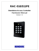
1.1. WALL TYPE
INDOOR
Unit
Nominal capacity adjustable
no no no no
Nominal Cooling capacity (min - max) kW
2.00 (0.90 - 2.50) 2.50 (0.90 - 3.10) 3.50 (0.90 - 4.00) 5.00 (1.90- 5.20)
Cooling sensible capacity kW
Nominal Heating capacity (min - max) kW
2.50 (0.90 - 3.20) 3.40 (0.90 - 4.40) 4.20 (0.90 - 5.00) 6.00 (2.2 - 7.30)
Noise level cooling (sound pressure)
(SL / L / M / H)
dB(A)
21 / 24 / 33 / 37 22 / 24 / 33 /40 25 / 26 / 36 / 43 28 / 30 / 40 / 46
Noise level heating (sound pressure)
(SL / L / M / H)
dB(A)
19 / 22 / 33 / 38 20 / 23 / 34 / 41 26 / 27 / 36 / 44 25 / 30 / 39 / 47
Noise level (sound power) dB(A)
51 54 57 60
Air flow cooling mode (SL / L / M /
3
312/350/400/440 333/370/430/510 333/400/485/600 333/450/600/700
Air flow heating mode (SL / L / M / H) m
3
312/350/420/480
/h
333/400/500/570 333/520/550/660 433/510/650/770
Fan Motor W
30 30 30 30
D l noitacifidimuhe /h
1.2 1.4 1.6
Dimensions (H x W x D) mm
280 x 780 x 215 280 x 780 x 215 280 x 780 x 215 280 x 780 x 215
W gk thgie
7.5 7.5 7.5 8
Colour
Condensate D mm niar
φ16mm
φ16mm
φ16mm
φ16mm
Running current (C/H) A
1.09-4.39/1.09-4.22 1.09-5.61/1.09-5.43
1.09-6.35/1.09-7.39
2.17-9.13/2.17-
11.96
Power supply
220-230V 220-230V 220-230V 220-230V
Cable section (Interconnection) mm ²
1.50x 3+EARTH/- 1.50x 3+EARTH/- 1.50x 3+EARTH/- 2.50x 3+EARTH/-
Piping diameter (Liq / Gas) Inch
1/4" / 3/8" 1/4" / 3/8" 1/4" / 3/8" 1/4" / 1/2"
Drain diameter (ext) mm
φ16mm
Remote control (standard/optional) *
RAR-5F1/SPX-
RCDB
RAR-5F1/SPX-
RCDB
RAR-5F1/SPX-
RCDB
RAR-5F1/SPX-
RCDB
Filter
NOTE:
1. The nominal cooling and heating capacity is the
combined capacity of the HITACHI standard split
system, and are based on the ISO 5151.
2. The Sound Pressure Level is based on the following
conditions:
- 0.8 meter beneath indoor height center
- 1 meter from Discharge grille
The above data was measured in an anechoic
chamber. Please take into consideration reflected
sound of your specific site
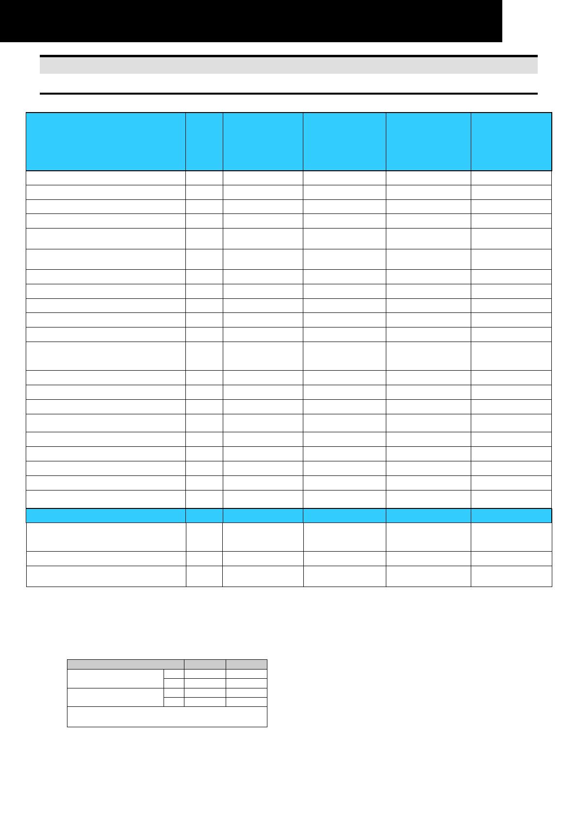
Operation Conditions Cooling Heating
Indoor Air Inlet Temperature
dB 27.0 °C 20.0 °C
WB 19.0 °C
Outdoor Air Inlet
Temperature
dB 35.0 °C 7.0 °C
WB
6.0 °C
Piping Length: 5.0 meters; Piping Lift: 0 meter
dB: Dry Bulb; WB: Wet Bulb
φ16mm φ16mm φ16mm
2.0
H) m /h
15.0 °C
24 .0 °C
2
ACL Filter
ACL part name PS X-CFH25 SPX-CFH25 SPX-CFH25 SPX-CFH25
Pre-filter (Standard/Optional)
Washable/
SPX-SPF8
Washable/
SPX-SPF8
Washable/
SPX-SPF8
Washable/
SPX-SPF8
RAK-18PED
RAK-25PED
RAK-25PEDC
RAS-X10EAG
RAS-L10EAG
RAS-M25EAG
RAK-35PED
RAK-35PEDC
RAS-X14EAG
RAS-L14EAG
RAS-M35EAG
RAK-50PED
RAK-50PEDC
RAS-X18EAG
RAS-M50EAG
1.99 2.28 2.87 3.47
Star White (N9.3) Star White (N9.3) Star White (N9.3) Star White (N9.3)
Activated carbon
(optional)
Activated carbon
(optional)
Activated carbon
(optional)
Activated carbon
(optional)
0