ENGLISH-16
Wired Remote Controller Installation/Service Mode
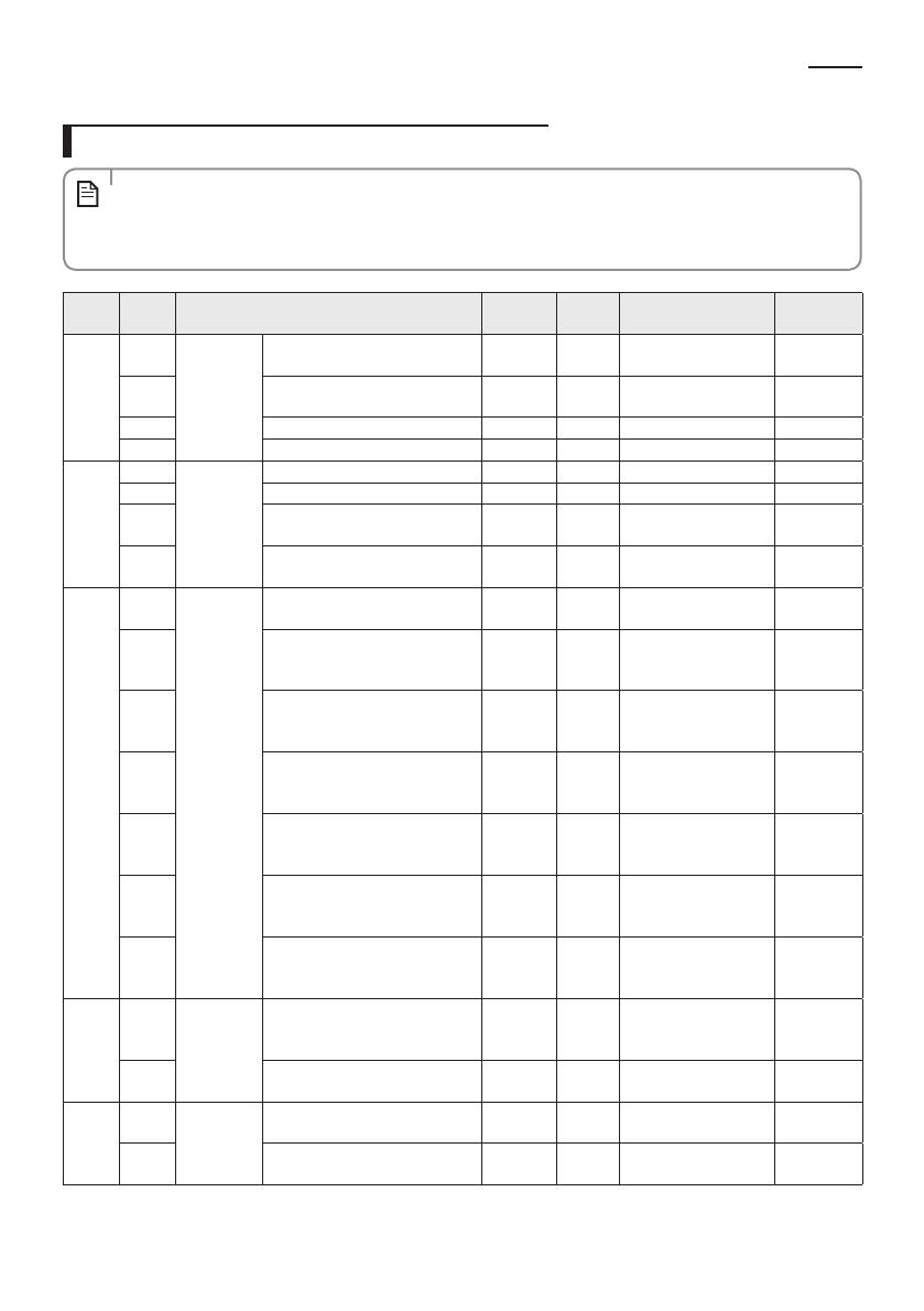
Additional Functions of Your Wired Remote Controller
• ‘NONE’ will be displayed if the indoor unit does not support the function. In some cases, the setting may not
possible or it may be not applied though it is set on the unit.
• If communication initialization is needed after the setting, the system will reset automatically and
communication will be initialized.
NOTE
Main
Menu
Sub
Menu
Function Default
Number
of pages
Description Remarks
0
1
Reset
Reset option setting of the wired
remote controller
0 1 0 - Disable, 1 - Reset
2
Reset wired remote controller as
factory default setting
0 1 0 - Disable, 1 - Reset
3 Power Master Reset 4)* 0 1 0 - Disable, 1 - Reset
4 Addressing Reset 0 1 0 - Disable, 1 - Reset
1
1
Wired
remote
controller
information
Check the number of indoor units 0 1 0~16
2 Check the number of ERV units 0 1 0~16 No function
3
Check the Micom Code of wired
remote controller
none 3 Micom code
4
Check the program version of
wired remote controller
none 3 Updated date
2
1
Address/
option
setting 2)*
Indoor unit setting (Target) View Master 3
Address of the
registered device
2
Set/Check the MAIN address of the
indoor unit
Main
address of
the target
1
MAIN address
[00H~4FH (hexadecimal
digits)]
3
Set/Check the RMC address of the
indoor unit
RMC
address of
the target
1
Group address
[00H~FEH (hexadecimal
digits)] 5)*
4
Set/Check the product option of
the indoor unit
Basic option
of the
target
10 1)* Indoor unit option code
5
Set/Check the installation option 1
of the indoor unit
Install
option of
the target
10 1)*
Refer to the installation
manual of the
connected indoor unit
6
Set/Check the installation option 2
of the indoor unit
Install (2)
option of
the target
10 1)*
Refer to the installation
manual of the
connected indoor unit
7 MCU/Port address setting
MCU
address of
target
2
MCU address (00 to 15)
Port address (A to F)
3
1
Set/Check
View Master
Set/check indoor unit View Master
Indoor
Units View
Master
3
Address of the
registered device
2 Set/check ERV unit View Master
ERV View
Master
3
Address of the
registered device
No function
4
1
Checking the
address of
mode master
indoor unit
Check the address of the mode
master indoor unit
none 3
Address of the mode
master indoor unit
2
Set the mode msater indoor
unit 3)*
none 1
0-Disable, 1-Enable,
2-Cancel
SOL WRControl_IM_EN_DB68-04148A-01.indd 16 2016-12-14 오후 1:15:22


