Page is loading ...


Revision history Table of revisions
Date Changed Rev
March 2020 Added adjustment details for threshold settings and changed document number from
AX00000025
0607
August 2019 Added caution for servo piston removal 0505
August 2018 update adjustment chapter 0504
April 2018 Major layout update, QF080 to QM050 updates 0503
January 2018 update pressure compensator torque values 0502
July 2016 Add G1, G2 controls 0501
December 2015 Add 210 frame size 0500
November 2015 Model code change 0400
July 2015 correct torque values, pages 61, 62 0301
June 2015 add hydraulic controls THHA, THHB 0300
2008-2015 First edition - and next various changes. AA-CB
Service Manual
H1 Bent Axis Motors, Size 060/080/110/160/210/250 cc
2 |
©
Danfoss | March 2020 AX152886484369en-000607

Introduction
About this manual............................................................................................................................................................................5
Warranty.............................................................................................................................................................................................. 5
General Instructions........................................................................................................................................................................ 5
Safety precautions............................................................................................................................................................................5
Symbols used in Danfoss literature............................................................................................................................................7
H1 general information
Design of H1 bent axis motor...................................................................................................................................................... 8
General description.......................................................................................................................................................................10
H1 pictorial diagram..................................................................................................................................................................... 11
H1 system schematic....................................................................................................................................................................12
Technical specifications
General specifications.................................................................................................................................................................. 13
Physical properties........................................................................................................................................................................ 13
Operating Parameters..................................................................................................................................................................14
H1B speed range diagrams for open and closed circuit..................................................................................................15
Required inlet pressure diagrams (for cylinder block filling).........................................................................................16
Open circuit requirements..........................................................................................................................................................17
Fluid specifications........................................................................................................................................................................18
Determination of nominal motor size....................................................................................................................................18
Operation
Shaft rotation direction................................................................................................................................................................19
Loop flushing shuttle spool........................................................................................................................................................21
Loop flushing relief valve............................................................................................................................................................22
Speed sensor................................................................................................................................................................................... 23
Displacement limiter.....................................................................................................................................................................23
Operating parameters
Output speed...................................................................................................................................................................................24
System pressure............................................................................................................................................................................. 24
Case pressure...................................................................................................................................................................................25
External shaft seal pressure........................................................................................................................................................25
Temperature....................................................................................................................................................................................25
Fluid and filter maintenance
Fluid and filter recommendations........................................................................................................................................... 26
Pressure measurements
Ports and Gauge Information....................................................................................................................................................27
Initial startup procedures
Procedure..........................................................................................................................................................................................29
Troubleshooting
Overview........................................................................................................................................................................................... 31
Electrical troubleshooting.......................................................................................................................................................... 31
Sluggish operation........................................................................................................................................................................ 31
System operating hot...................................................................................................................................................................31
Excessive noise or vibration.......................................................................................................................................................32
Motor operates normally in one direction only..................................................................................................................32
Improper output speed............................................................................................................................................................... 32
Low output torque........................................................................................................................................................................ 33
Required tools and standard procedures
Adjustments
Optional threshold adjustment – Electric proportional controls................................................................................. 36
Optional threshold adjustment – Hydraulic proportional controls.............................................................................37
Pressure Compensator OverRide (PCOR) adjustment......................................................................................................38
Minor repair
Service Manual
H1 Bent Axis Motors, Size 060/080/110/160/210/250 cc
Contents
©
Danfoss | March 2020 AX152886484369en-000607 | 3

Shaft seal...........................................................................................................................................................................................41
Electric proportional solenoid replacement........................................................................................................................ 43
Hydraulic proportional actuator replacement....................................................................................................................44
Control module replacement....................................................................................................................................................45
Electric proportional control module.....................................................................................................................................47
Hydraulic proportional control module.................................................................................................................................50
Electric two-position control module.....................................................................................................................................52
Hydraulic two-position control module................................................................................................................................ 55
Hydraulic two-position control module with PCOR..........................................................................................................56
Hydraulic two-position control module with PCOR and hydraulic BPD....................................................................57
Maximum displacement limiter two-position controls................................................................................................... 59
Servo piston cover – proportional control............................................................................................................................60
Replace speed sensor...................................................................................................................................................................63
Loop flushing spool.......................................................................................................................................................................64
Loop flushing charge relief valve.............................................................................................................................................65
Minimum Displacement limiter................................................................................................................................................66
Torque chart
Fasteners, plugs with torque chart..........................................................................................................................................67
Service Manual
H1 Bent Axis Motors, Size 060/080/110/160/210/250 cc
Contents
4 |
©
Danfoss | March 2020 AX152886484369en-000607

About this manual
This manual includes information for the installation, maintenance, and minor repair procedures for H1
bent axis motors. It includes a description of the unit and its individual components, troubleshooting
information, and minor repair procedures.
Performing minor repairs may require removal from the vehicle/machine. Thoroughly clean the unit
before beginning maintenance or repair activities. Since dirt and contamination are the greatest enemies
of any type of hydraulic equipment, follow cleanliness requirements strictly. This is especially important
when changing the system filter and when removing hoses or plumbing.
Only Danfoss global service partners (GSPs) are authorized to perform major repairs.Danfoss trains Global
Service Partners and certifies their facilities on a regular basis. You can locate your nearest service partner
at www.danfoss.com > Contact us > Danfoss sales and services > Distributor and service partners
Warranty
Performing installation, maintenance, and minor repairs according to the procedures in this manual will
not affect your warranty. Major repairs requiring the removal of a unit’s rear cover voids the warranty
unless done by a Danfoss Global Service Partner.
General Instructions
When repairing H1 variable displacement closed circuit motors follow these general procedures:
Remove the unit Chock the wheels on the vehicle or lock the mechanism to inhibit movement.
Prior to performing repairs, remove the unit from the vehicle/machine. Be aware
that hydraulic fluid may be under high pressure and/or hot. Inspect the outside of
the motor and fittings for damage. Cap hoses after removal to prevent
contamination.
Keep it clean Cleanliness is a primary means of assuring satisfactory motor life, on either new or
repaired units. Clean the outside of the motor thoroughly before disassembly.
Take care to avoid contamination of the system ports. Cleaning parts with a clean
solvent wash and air drying is usually adequate. Keep all parts free of foreign
materials and chemicals. Protect all exposed sealing surfaces and open cavities
from damage and foreign material.
Lubricate moving
parts
During assembly, coat all moving parts with a film of clean hydraulic oil. This
assures that these parts are lubricated during start-up.
Replace all O-rings
and gaskets
Danfoss recommends you replace all O-rings and gaskets during repair. Lightly
lubricate O-rings with clean petroleum jelly prior to assembly.
Secure the unit For repair, place the unit in a stable position with the shaft pointing downward.
Secure the motor while removing and torquing components and fasteners.
Safety precautions
Always consider safety precautions before beginning a service procedure. Protect yourself and others
from injury. Take the following general precautions whenever servicing a hydraulic system.
Service Manual
H1 Bent Axis Motors, Size 060/080/110/160/210/250 cc
Introduction
©
Danfoss | March 2020 AX152886484369en-000607 | 5

Unintended machine movement
W
Warning
Unintended movement of the machine or mechanism may cause injury to the technician or bystanders.
To protect against unintended movement, secure the machine or disable/disconnect the mechanism
while servicing.
Flammable cleaning solvents
W
Warning
Some cleaning solvents are flammable. To avoid possible fire, do not use cleaning solvents in an area
where a source of ignition may be present.
Fluid under pressure
W
Warning
Escaping hydraulic fluid under pressure can have sufficient force to penetrate your skin causing serious
injury and/or infection. This fluid may also be hot enough to cause burns. Use caution when dealing with
hydraulic fluid under pressure. Relieve pressure in the system before removing hoses, fittings, gauges, or
components. Never use your hand or any other body part to check for leaks in a pressurized line. Seek
medical attention immediately if you are cut by hydraulic fluid.
Personal safety
W
Warning
Protect yourself from injury. Use proper safety equipment, including safety glasses, at all times.
Hazardous material
W
Warning
Hydraulic fluid contains hazardous material. Avoid prolonged contact with hydraulic fluid. Always
dispose of used hydraulic fluid according to environmental regulations.
Service Manual
H1 Bent Axis Motors, Size 060/080/110/160/210/250 cc
Introduction
6 |
©
Danfoss | March 2020 AX152886484369en-000607

Symbols used in Danfoss literature
WARNING may result in injury Tip, helpful suggestion
CAUTION may result in damage to product or
property
Lubricate with hydraulic fluid
Reusable part Apply grease / petroleum jelly
Non-reusable part, use a new part Apply locking compound
Non-removable item Inspect for wear or damage
Option - either part may exist Clean area or part
Superseded - parts are not interchangeable Be careful not to scratch or damage
Measurement required Note correct orientation
Flatness specification Mark orientation for reinstallation
Parallelism specification Torque specification
External hex head Press in - press fit
Internal hex head Pull out with tool – press fit
Torx head Cover splines with installation sleeve
O-ring boss port Pressure measurement/gauge location or
specification
The symbols above appear in the illustrations and text of this manual. They are intended to communicate
helpful information at the point where it is most useful to the reader. In most instances, the appearance
of the symbol itself denotes its meaning. The legend above defines each symbol and explains its purpose.
Service Manual
H1 Bent Axis Motors, Size 060/080/110/160/210/250 cc
Introduction
©
Danfoss | March 2020 AX152886484369en-000607 | 7

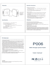
Design of H1 bent axis motor
Cross-section of H1 motor with electric proportional control
P005 917
6
7
5
1
2
3
4
10
9
8
1. Differential servo piston
2. Valve segment
3. Bearing plate
4. Tapered roller bearing
5. Loop flushing relief valve
6. Ramp spring
7. Loop flushing shuttle spool
8. Electric proportional control
9. Minimum displacement limiter
10. Speed ring (optional)
Service Manual
H1 Bent Axis Motors, Size 060/080/110/160/210/250 cc
H1 general information
8 |
©
Danfoss | March 2020 AX152886484369en-000607

Cross-section of H1 motor with electric two-position control
P005 918
1
2
3
4
7
6
5
9
8
1. Differential servo piston
2. Valve segment
3. Bearing plate
4. Tapered roller bearing
5. Loop flushing relief valve
6. Loop flushing shuttle spool
7. Electric two-position control
8. Minimum displacement limiter
9. Speed ring (optional)
Service Manual
H1 Bent Axis Motors, Size 060/080/110/160/210/250 cc
H1 general information
©
Danfoss | March 2020 AX152886484369en-000607 | 9

General description
Series H1 variable displacement motors are bent axis design, incorporating spherical pistons.
These motors are designed primarily to be combined with other products in closed circuit systems to
transfer and control hydraulic power. Series H1 motors have a large maximum/minimum displacement
ratio of 5:1 and high output speed capabilities.
The expanded function of zero degree capability, coupled with a high performance 32 degree maximum
angle, creates opportunities to easily improve the machine performance for:
•
Wheel assist on the steering axle of high inertia machines (i.e. combines) and could include Anti Slip
Control
•
Off-highway machines requiring Anti Slip Control (i.e. Ag. sprayer)
•
Multi-motor applications requiring optimized work and transport modes (i.e. wheel loader, Ag
sprayer) utilizing the zero degree position for maximum transport speed
•
Improved machine (i.e. single drum roller) gradeability through precise Anti Slip Control
The Anti Slip Control reduces ground damage, increases traction control and improves machine
controllability for the operator.
SAE, Cartridge (not available for 210 cm
3
and 250 cm
3
) and DIN flange with radial or axial high pressure
port configurations are available including the loop flushing device.
A complete family of controls and regulators are available to fulfill the requirements of a wide range of
applications.
Motors normally start at maximum displacement. This provides maximum starting torque for high
acceleration.
All controls utilize internally supplied servo pressure. This may be overridden by a pressure compensator
which functions when the motor is operating in motor and pump modes. A defeat option is available to
disable the pressure compensator override when the motor is running in pump mode during
deceleration/braking.
The pressure compensator option features a low pressure rise to ensure optimal power utilization
throughout the entire displacement range of the motor.
Speed sensor options are available to cover all frame sizes and flange styles.
They are capable of sensing the following, all in one package:
•
Speed
•
Direction (only group "J", option "S")
•
Temperature (only group "J", option "S")
The electric controls are specifically designed for the Danfoss family of PLUS+1
®
microcontrollers for
easy "Plug and Perform" installation.
Service Manual
H1 Bent Axis Motors, Size 060/080/110/160/210/250 cc
H1 general information
10 |
©
Danfoss | March 2020 AX152886484369en-000607

H1 pictorial diagram
P003 423
2
3
6
7
4
10
8
9
16
15
14
13
12
11
17
5
7
18
1
5
Working loop A (Low pressure) and charge pressure
Working loop B (High pressure)
Servo pressure
Case drain
Suction
1. Bent Axis Variable Displacement Motor
2. Axial Piston Variable Displacement Pump
3. Electric Displacement Control (EDC)
4. Charge Pump
5. Charge Check / High Pressure Relief Valve
6. Loop Flushing Valve
7. Pressure Limiter Valve
8. Charge Pressure Relief Valve
9. Servo Cylinder
10. Charge Pressure Filter
11. Heat Exchanger
12. Heat Exchanger Bypass Valve
13. Valve Segment
14. Pump Swashplate
15. Input Shaft
16. Output Shaft
17. Reservoir
18. to Motor Case
Service Manual
H1 Bent Axis Motors, Size 060/080/110/160/210/250 cc
H1 general information
©
Danfoss | March 2020 AX152886484369en-000607 | 11

H1 system schematic
System schematic H1 pump and H1 motor with EDC
P003 424
min.max.
L2 NMA
A
B
M5
MB
M4
L1
B
R1
R2
M4
M5
M14 M6 1 2
M3 L1 L2 MA
A
C2 C1
S
F00B F00A
L3 L4
CW
MB
max. 3 bar
[43.5 psi]
n
The schematic above shows the function of a hydrostatic transmission using an H1 axial variable displacement pump with electric
proportional displacement control (EDC) and an H1 bent axis variable displacement motor with electric proportional control (L*) and
integrated loop flushing device.
Service Manual
H1 Bent Axis Motors, Size 060/080/110/160/210/250 cc
H1 general information
12 |
©
Danfoss | March 2020 AX152886484369en-000607

General specifications
General specifications
Design
Piston motor with variable displacement bent axis design
Direction of rotation
Bi-directional
Pipe connections
Main pressure ports: ISO split flange boss
Remaining ports: SAE straight thread O-ring boss
Recommended installation
Discretionary, the housing must always be filled with hydraulic fluid
Physical properties
Physical properties
Features Unit
Size
060 080 110 160 210 250
Displacement
maximum
cm
3
[in
3
]
60 [3.66] 80 [4.88] 110 [6.71] 160 [9.76] 210 [12.81] 250 [15.25]
minimum
12 [0.73] 16 [0.98] 22 [1.34] 32 [1.95] 42 [2.56] 50 [3.05]
Theoretical flow at
max. displ.
at rated speed
l/min
[US gal/min]
216 [57] 256 [68] 319 [84] 416 [110] 504 [133] 550 [145]
at max. speed
270 [71] 328 [87] 407 [108] 528 [139] 630 [166] 700 [185]
Theoretical torque
at max. displacement
N•m/bar
[lb•in/1000 psi]
0.96 [583] 1.27 [777] 1.75 [1069] 2.55 [1555] 3.34 [2038] 3.98 [2426]
Theor. corner power at rated speed and max.
working pressure (∆p = 450 bar [6527 psi])
kW [hp] 266 [357] 321 [430] 396 [531] 513 [689] 609 [817] 684 [917]
Mass moment of inertia of rotating
components
kg•m
2
[slug•ft
2
]
0.0038
[0.0028]
0.0062
[0.0046]
0.0108
[0.0080]
0.0211
[0.0156]
0.0306
[0.0226]
0.0402
[0.0296]
Case volume
l [US gal] 0.9 [0.24] 1.0 [0.26] 1.4 [0.37] 2.7 [0.71] 2.8 [0.74] 4.1 [1.08]
Weight dry (Electric proportional control)
Configuration Size
060 080 110 160 210 250
SAE
29.8 kg [65.7 lb] 34.8 kg [76.7 lb] 48.8 kg [107.6 lb] 61.9 kg [136.5 lb] 81.0 kg [179 lb] 87.0 kg [196.2 lb]
DIN
28.3 kg [62.4 lb] 34.4 kg [75.8 lb] 45.0 kg [99.2 lb] 59.3 kg [130.7 lb] 75.0 kg [165 lb] 79.6 kg [175.5 lb]
Cartridge
26.9 kg [59.3 lb] 33.0 kg [72.6 lb] 41.8 kg [92.2 lb] 54.7 kg [120.6 lb] – –
Mounting flange
Configuration Size
060 080 110 160 210 250
SAE ISO 3019/1
127-4 (SAE C) 4-bolt 152-4 (SAE-D) 4-bolt 165-4 (SAE E)
DIN ISO 3019/2, B4
125 HL 4-bolt 140 HL 4-bolt 160 HL 4-bolt 180 HL 4-bolt 200 HL 4-bolt
200 HL 4-bolt
Cartridge
Pilot Ø160 mm
2-bolt (200 dist.)
M16
Pilot Ø190 mm
2-bolt (224 dist.)
M20
Pilot Ø200 mm
2-bolt (250 dist.) M20 – –
Service Manual
H1 Bent Axis Motors, Size 060/080/110/160/210/250 cc
Technical specifications
©
Danfoss | March 2020 AX152886484369en-000607 | 13

Customer ports
Size 060 080 110 160 210 250
Axial and radial
1)
DN19 typ 1 DN25 typ 1 DN25 typ 1 DN32 typ 1 DN32 typ 1 DN32 typ 1
Case drain ports
2)
0.875 [
7
∕
8
]–14UN-2B 1.0625 [1
1
∕
16
]–12UN-2B 1.313 [1
5
∕
16
]–12UN-2B]
Axial gauge
ports
2)3)
0.875 [
7
∕
8
]–14UN-2B
1.0625 [1
1
∕
16
]–12UN-2B
Radial gauge
port
2)3)
0.5625 [
9
∕
16
]–18UNF-2B
1)
Split flange Boss per ISO6162, 40 MPa series
2)
SAE O-ring boss
3)
Countersink may be deeper that specified in the standard.
Operating Parameters
Output Speed
Output Speed Displacement Unit
Size
060 080 110 160 210 250
Rated
Maximum 32°
min
-1
(rpm)
3600 3200 2900 2600 2350 2200
Minimum 6° 5900 5300 4800 4250 3850 3650
Zero 0° 6600 5950 5350 4750 4300 4050
Maximum
Maximum 32° 4500 4100 3700 3300 3000 2800
Minimum 6° 7250 6600 5950 5250 4800 4500
Zero 0° 7950 7200 6500 5750 5250 4900
System and Case Pressure, Ambient Temperature
Parameter All sizes
System pressure Maximum working 450 bar [6527 psi]
Maximum 480 bar [6962 psi]
Minimum
1) 2)
Case pressure Rated 3 bar [44 psi]
Maximum 5 bar [73 psi]
Minimum 0.3 bar [4 psi]
Ambient temperature
3)
Maximum 70 °C [158 °F]
Minimum -40 °C [-40 °F]
1)
Minimum above case pressure (open and closed circuit)
2)
See the graphs Required inlet pressure diagrams (for cylinder block filling) on page 16.
3)
Air temperature close to the unit.
Service Manual
H1 Bent Axis Motors, Size 060/080/110/160/210/250 cc
Technical specifications
14 |
©
Danfoss | March 2020 AX152886484369en-000607

H1B speed range diagrams for open and closed circuit
Speed (rpm) versus Displacement (%), Intermittent operation (grey area)
P003 557
0
1000
2000
3000
4000
5000
6000
7000
8000
0% 20% 40% 60% 80% 100%
H1B 060
0
1000
2000
3000
4000
5000
6000
7000
8000
P003 509
0% 20% 40% 60% 80% 100%
H1B 080
0
1000
2000
3000
4000
5000
6000
7000
P003 511
0% 20% 40% 60% 80% 100%
H1B 110
0% 20% 40% 60% 80% 100%
P301 307
0
1000
2000
3000
4000
5000
6000
7000
H1B 160
0
1000
2000
3000
4000
5000
6000
P006 001
0% 20% 40% 60% 80% 100%
H1B 210
0
1000
2000
3000
4000
5000
6000
0% 20% 40% 60% 80% 100%
P301 457
H1B 250
W
Warning
Zero degree capability results in a high risk of overspeed and drops in efficiency if the motor operates between 0–20% displacement.
For open circuit applications it is not allowed to operate in the intermitent area.
For closed circuit applications operating in the intermittent area, please contact your local Danfoss Power Solutions representative.
Service Manual
H1 Bent Axis Motors, Size 060/080/110/160/210/250 cc
Technical specifications
©
Danfoss | March 2020 AX152886484369en-000607 | 15

Required inlet pressure diagrams (for cylinder block filling)
Speed (rpm) and Pressure (bar) versus Displacement (%)
0
1000
2000
3000
4000
5000
6000
7000
8000
9000
0% 20% 40%
60%
80% 100%
P006 010
30bar
20bar
15bar
10bar
5bar
2bar
H1B 060
1000
2000
3000
4000
5000
6000
7000
8000
0
0% 20% 40%
60%
80% 100%
P006 011
30bar
20bar
15bar
10bar
5bar
2bar
H1B 080
Speed (rpm) and Pressure (bar) versus Displacement (%)
1000
2000
3000
4000
5000
6
7000
000
0% 20% 40%
60%
80% 100%
P006 012
30bar
20bar
15bar
10bar
5bar
2bar
0
H1B 110
1000
2000
3000
4000
5000
6
7000
000
0% 20% 40%
60%
80% 100%
P006 013
30bar
20bar
15bar
10bar
5bar
2bar
0
H1B 160
Speed (rpm) and Pressure (bar) versus Displacement (%)
0% 20% 40%
60%
80% 100%
P006 014
30bar
20bar
15bar
10bar
5bar
2bar
0
1000
2000
3000
4000
5000
6000
H1B 210
0% 20% 40%
60%
80% 100%
P006 015
30bar
20bar
15bar
10bar
5bar
2bar
0
1000
2000
3000
4000
5000
6000
H1B 250
Bold dashed line: Maximum speed
Bold solid line: Rated speed
This pressure ensures that the cylinder block will be properly filled and that there is no pulling between piston and shaft.
The required pressure is 0 bar at 0 rpm and increases with rpm.
For open circuit applications it is not allowed to operate above rated speed. For closed circuit applications operating between rated
and max. speed, please contact your local Danfoss Power Solutions representative.
Service Manual
H1 Bent Axis Motors, Size 060/080/110/160/210/250 cc
Technical specifications
16 |
©
Danfoss | March 2020 AX152886484369en-000607

Open circuit requirements
H1 Bent Axis Motors may be used in Open Circuit (OC) applications.
Since loop flushing is typically not used in OC-applications it is essential to provide sufficient cooling
capacity. This can be done by motor case cross flushing.
The flow rate needs to be adjusted to the cooling demand.
The highest case drain outlet port must always be used for the return flow to the cooler or tank.
The motor case, the control system and the working lines connected to Port A and B must be kept full of
oil at all times, whether in a dynamic or static condition.
The plumbing must not allow the oil to drain down and be replaced with air in the control or rotating
group.
The minimum pressure in the inlet port and the outlet port, measured at gage ports MA and MB, must be
equal or higher as shown in the graphs Required inlet pressure diagrams (for cylinder block filling) on page
16.
Counter balance valves may be used to maintain the minimum pressure requirements. Also the Danfoss
Power Solutions Meter-in / Meter-out PVG technology may be used.
Check valves and sufficient charge pressure supply are also possible.
At no time shall the motor be allowed to operate above the rated speed limits. If flow limiter valves are
used, they must be selected accordingly. Select Motor controls which use the high loop system pressure
to shift the servo piston. This will ensure proper function under all conditions.
Valve blocks, such as counter balance valves attached to the inlet and/or outlet ports, must not interfere
with any part of the motor. A review of the outline drawings or appropriate 3D models must be
completed.
Service Manual
H1 Bent Axis Motors, Size 060/080/110/160/210/250 cc
Technical specifications
©
Danfoss | March 2020 AX152886484369en-000607 | 17

Fluid specifications
Fluid specifications
Features Unit
All sizes
Viscosity
Minimum intermittent
mm
2
/s
[SUS]
7 [49]
Recommended range
12-80 [66-366]
Maximum intermittent
1600 [7416]
Temperature range
1)2)
Minimum
°C
[°F]
-40 [-40]
Rated
104 [220]
Maximum intermittent
115 [240]
Cleanliness and Filtration
Required cleanliness per ISO 4406
-
22/18/13
Efficiency (charge pressure filtration)
β-ratio
β
15-20
= 75 (β
10
≥ 10)
Efficiency (suction / return line filtration)
β
35-45
= 75 (β
10
≥ 2)
Recommended inlet screen mesh size
µm 100 – 125
1)
At the hottest point, normally case drain port.
2)
Minimum: cold start, short term t<3 min, p<50 bar, n<1000 rpm.
Determination of nominal motor size
Based on SI units Based on US units
V
g
• n
1000 •
v
Q
e
=
V
g
• p •
mh
20 •
M
e
=
Q
e
• p •
t
600
=
M
e
• n
9550
P
e
=
n =
Q
e
• 1000 •
v
V
g
V
g
• n
231 •
v
Q
e
=
V
g
• p •
mh
2 •
M
e
=
V
g
• n • p •
t
396 000
P
e
=
n =
Q
e
• 231 •
v
V
g
Where:
Q
e
Input flow (l/min)
M
e
Output torque (N•m)
P
e
Output power (kW)
n Speed (min
-1
)
V
g
Motor displacement per rev. (cm
3
/rev)
p
high
High pressure (bar)
p
low
Low pressure (bar)
∆p High pressure minus Low pressure (bar)
η
v
Motor volumetric efficiency
η
mh
Mechanical-hydraulic efficiency
η
t
Motor total efficiency (η
v
• η
mh
)
Where:
Q
e
Input flow [US gal/min]
M
e
Output torque [lb•in]
P
e
Output power [hp]
n Speed [rpm]
V
g
Motor displacement per rev. [in
3
/rev]
p
high
High pressure [psi]
p
low
Low pressure [psi]
∆p High pressure minus Low pressure [psi]
η
v
Motor volumetric efficiency
η
mh
Mechanical-hydraulic efficiency
η
t
Motor total efficiency (η
v
• η
mh
)
Service Manual
H1 Bent Axis Motors, Size 060/080/110/160/210/250 cc
Technical specifications
18 |
©
Danfoss | March 2020 AX152886484369en-000607

Shaft rotation direction
Shaft rotation direction is determined with a view from the shaft end.
Rotation direction of the motor will be dependent on the control option used as illustrated below.
In the second number or letter of the control code, 1 means 12 V
DC
, 2 means 24 V
DC
, and H means
hydraulic.
Controls L1, L2, D1, D2, LH, DH
CCW CW
P006030
B
A
Flow into port A Clockwise
Flow into port B Counterclockwise
Controls M1, M2, K1, K2, KH, MH
CCW CW
P006031
B
A
Flow into port A Counterclockwise
Flow into port B Clockwise
Service Manual
H1 Bent Axis Motors, Size 060/080/110/160/210/250 cc
Operation
©
Danfoss | March 2020 AX152886484369en-000607 | 19

Controls E1, E2, F1, F2, P1, P2, T1, T2, TA, TH, HE, HF
CCW CW
P006032
B
A
Flow into port A Counterclockwise
Flow into port B Clockwise
Service Manual
H1 Bent Axis Motors, Size 060/080/110/160/210/250 cc
Operation
20 |
©
Danfoss | March 2020 AX152886484369en-000607
/