Page is loading ...

M212305EN-A
User Guide
Intrinsically Safe Humidity and Temperature
Transmitter Series
HMT370EX

PUBLISHED BY
Vaisala Oyj
Vanha Nurmijärventie 21, FI-01670 Vantaa, Finland
P.O. Box 26, FI-00421 Helsinki, Finland
+358 9 8949 1
Visit our Internet pages at www.vaisala.com.
© Vaisala 2021
No part of this document may be
reproduced, published or publicly
displayed in any form or by any means,
electronic or mechanical (including
photocopying), nor may its contents be
modified, translated, adapted, sold or
disclosed to a third party without prior
written permission of the copyright holder.
Translated documents and translated
portions of multilingual documents are
based on the original English versions. In
ambiguous cases, the English versions are
applicable, not the translations.
The contents of this document are subject
to change without prior notice.
Local rules and regulations may vary and
they shall take precedence over the
information contained in this document.
Vaisala makes no representations on this
document’s compliance with the local
rules and regulations applicable at any
given time, and hereby disclaims any and
all responsibilities related thereto.
This document does not create any legally
binding obligations for Vaisala towards
customers or end users. All legally binding
obligations and agreements are included
exclusively in the applicable supply
contract or the General Conditions of Sale
and General Conditions of Service of
Vaisala.
This product contains software developed
by Vaisala or third parties. Use of the
software is governed by license terms and
conditions included in the applicable
supply contract or, in the absence of
separate license terms and conditions, by
the General License Conditions of Vaisala
Group.

Table of contents
1. About this document.....................................................................................7
1.1 Version information.......................................................................................... 7
1.2 Related manuals................................................................................................7
1.3 Documentation conventions............................................................................7
1.4 Trademarks........................................................................................................ 7
2. Product overview............................................................................................ 9
2.1 Introduction to HMT370EX series...................................................................9
2.2 Basic features and options.............................................................................. 9
2.3 Hazardous area safety......................................................................................9
2.4 Available measurement parameters.............................................................10
2.5 Display options................................................................................................. 11
2.5.1 LED states in transmitter with no display..............................................12
2.6 Connectivity to Vaisala Insight software...................................................... 12
2.7 Transmitter parts............................................................................................. 13
2.7.1 Cable gland and conduit options...........................................................14
2.8 Using HTM370EX Series transmitters in hazardous locations...................16
2.8.1 Guidelines for safe use in hazardous conditions.................................. 17
3. Probe options..................................................................................................21
3.1 HMT370EX probe options overview..............................................................21
3.1.1 HMT370EX probe accessories............................................................... 22
3.2 HMP371 fixed probe........................................................................................23
3.3 HMP373 probe for confined spaces..............................................................23
3.4 HMP374 probe for high pressure applications............................................25
3.5 HMP375 probe for high temperature applications.....................................26
3.6 HMP377 probe for high humidity applications........................................... 27
3.7 HMP378 probe for pressurized pipelines.....................................................28
3.7.1 Attaching ball valve kit to process........................................................30
3.7.2 HMP378F probe option for measuring oil moisture and
temperature.............................................................................................. 31
3.7.3 HMP378H probe option for measuring fuel moisture and
temperature.............................................................................................. 31
4. Installation....................................................................................................... 33
4.1 HMT370EX installation overview..................................................................33
4.1.1 Installation preparations........................................................................ 34
4.1.2 Probe installation overview....................................................................35
4.1.3 HMT370EX transmitter dimensions...................................................... 35
4.2 Mounting......................................................................................................... 36
4.3 Attaching cable glands and conduit fittings............................................... 37
4.4 Wiring.............................................................................................................. 38
4.4.1 Wiring with galvanic isolators...............................................................40
4.4.2 Wiring with Zener barriers......................................................................41
4.5 Finalizing installation: closing transmitter and attaching grounding...... 42
4.6 Optional: testing analog output level with a multimeter.......................... 43
Table of contents
1

5. HMT370 local display interface..............................................................46
5.1 Local display overview.................................................................................. 46
5.1.1 Local display PIN code........................................................................... 48
5.1.2 Light and dark display themes..............................................................49
5.1.3 Sleep mode..............................................................................................49
5.2 HMT370EX display main menu.....................................................................50
5.3 Settings menu.................................................................................................50
5.3.1 Display menu............................................................................................ 51
5.3.2 Analog outputs menu ............................................................................ 52
5.3.3 Measurement settings menu..................................................................52
5.4 Calibration menu............................................................................................ 53
5.5 Status menu.................................................................................................... 53
5.6 Maintenance menu.........................................................................................54
6. Operating with Insight PC software......................................................55
6.1 Vaisala Insight PC software........................................................................... 55
6.1.1 Basic and Advanced user modes.......................................................... 55
6.2 Connecting to Insight PC software...............................................................55
6.2.1 Installing driver for the USB service cable........................................... 57
6.3 Insight main view with transmitter...............................................................59
6.4 Insight main view with probe.......................................................................60
7. Analog output configuration.................................................................... 61
7.1 Analog output configuration overview.........................................................61
7.2 Configuring analog outputs with Insight.....................................................62
7.3 Configuring analog outputs with local display interface...........................62
7.4 Analog output level test................................................................................ 63
7.4.1 Testing analog output level with local display interface.................... 63
7.4.2 Testing analog output level with Insight..............................................64
8. Environmental compensation and measurement settings..........66
8.1 Environmental compensation and measurement settings overview...... 66
8.2 Configuring pressure compensation............................................................67
8.3 Configuring filtering factor............................................................................68
8.4 Configuring calculation coecients............................................................ 69
8.4.1 HMP378F calculation model with average oil coecients................ 69
8.4.2 HMP378F calculation model with oil-specific coecients................ 70
9. Calibration and adjustment.......................................................................71
9.1 Calibration and adjustment overview........................................................... 71
9.2 Adjusting measurements with Insight......................................................... 72
9.3 Adjusting measurements with HMT370EX local display interface...........72
9.4 Analog output adjustment overview........................................................... 74
9.4.1 Adjusting analog output level with Insight.......................................... 76
9.4.2 Adjusting analog output level with local display interface................ 77
HMT370EX User Guide M212305EN-A
2

10. Maintenance....................................................................................................78
10.1 Overview..........................................................................................................78
10.1.1 Technical support.................................................................................... 78
10.2 Cleaning...........................................................................................................78
10.3 Changing probe filter..................................................................................... 78
11. Troubleshooting............................................................................................80
11.1 Problems and their possible solutions........................................................ 80
11.2 Error messages................................................................................................ 81
11.3 Restoring factory default settings................................................................82
12. Technical data................................................................................................84
12.1 Specifications..................................................................................................84
12.2 HMP371 specifications....................................................................................88
12.3 HMP373 specifications...................................................................................88
12.4 HMP374 specifications...................................................................................89
12.5 HMP375 specifications.................................................................................. 90
12.6 HMP377 specifications....................................................................................91
12.7 HMP378 specifications...................................................................................92
12.8 Spare parts and accessories..........................................................................93
12.9 Recycling instructions....................................................................................94
Maintenance and calibration services........................................................ 99
Warranty............................................................................................................99
Technical support............................................................................................99
Recycling...........................................................................................................99
Table of contents
3

List of figures
Figure 1 HMT370EX transmitter display options......................................................11
Figure 2 HMT370EX transmitter external parts....................................................... 13
Figure 3 HMT370EX transmitter internal parts........................................................14
Figure 4 Default plugs in HMT370EX lead-throughs..............................................15
Figure 5 HMT370EX parts overview............................................................................17
Figure 6 Location of test points and service port................................................... 19
Figure 7 HMT370EX probe options............................................................................. 21
Figure 8 Dimensions in mm (inches)..........................................................................23
Figure 9 Dimensions in mm (inches)..........................................................................23
Figure 10 Left: Installation kit for duct mounting. Right:
Installation flange. Aluminum or stainless steel.....................................24
Figure 11 Dimensions in mm (inches)..........................................................................25
Figure 12 HMP375 probe and stainless steel installation flange.
Dimensions in mm (inches)..........................................................................26
Figure 13 Dimensions in mm (inches)..........................................................................27
Figure 14 Dimensions in mm (inches)..........................................................................29
Figure 15 Example wall installation with HMP373 probe........................................33
Figure 16 Duct installation example with HMP373 probe and duct
installation kit...................................................................................................35
Figure 17 HMT370EX transmitter dimensions...........................................................35
Figure 18 Mounting HMT370EX directly through the transmitter body............ 36
Figure 19 Wiring example using one cable................................................................ 39
Figure 20 Wiring diagram with galvanic isolators................................................... 40
Figure 21 Wiring diagram with Zener barriers........................................................... 41
Figure 22 Multimeter test point overview.................................................................. 44
Figure 23 HMT370EX local display examples: measurement graph
view and main menu screen........................................................................46
Figure 24 HMT370EX display interface buttons....................................................... 46
Figure 25 2 parameter view example...........................................................................47
Figure 26 Graph view example.......................................................................................47
Figure 27 Parameter list view example....................................................................... 48
Figure 28 Display PIN code button presses............................................................... 48
Figure 29 Dark (left) and light (right) display theme examples...........................49
Figure 30 Transmitter display in sleep mode.............................................................49
Figure 31 HMT370EX display interface main menu.................................................50
Figure 32 Settings menu................................................................................................. 50
Figure 33 Display menu.....................................................................................................51
Figure 34 Analog output settings................................................................................. 52
Figure 35 Calibration menu.............................................................................................53
Figure 36 Status menu......................................................................................................53
Figure 37 Maintenance menu.........................................................................................54
Figure 38 Connecting to Insight: probe body and transmitter
service port locations.................................................................................... 56
Figure 39 Insight main menu and settings: transmitter view................................59
Figure 40 Insight main menu and settings: probe view..........................................60
HMT370EX User Guide M212305EN-A
4

Figure 41 Analog output configuration options in Insight PC software..............61
Figure 42 Multimeter test point overview...................................................................63
Figure 43 Filtering factor configuration in Insight PC software............................68
Figure 44 Insight PC software calibration view example.........................................71
Figure 45 Local display calibration menu.................................................................... 71
Figure 46 Analog output level adjustment in Insight PC software...................... 76
Figure 47 Humidity measurement accuracy as function of temperature.......... 85
Figure 48 Temperature measurement accuracy over full range........................... 85
Figure 49 A
w
measurement accuracy.......................................................................... 86
Figure 50 HMT370EX transmitter dimensions...........................................................88
Figure 51 Dimensions in mm (inches)..........................................................................88
Figure 52 Dimensions in mm (inches)......................................................................... 89
Figure 53 Dimensions in mm (inches)......................................................................... 90
Figure 54 HMP375 probe and stainless steel installation flange.
Dimensions in mm (inches).......................................................................... 91
Figure 55 Dimensions in mm (inches)..........................................................................92
Figure 56 Dimensions in mm (inches)..........................................................................93
Figure 57 Recyclable and non-recyclable parts in transmitters
with no display................................................................................................ 95
Figure 58 Recyclable and non-recyclable parts in transmitters
with no display after disposing of electronics and probe...................95
Figure 59 Recyclable and non-recyclable parts in transmitters with display... 95
Figure 60 Recyclable and non-recyclable parts in transmitters
with display after disposing of electrical and electronic waste.........95
List of figures
5

List of tables
Table 1 Document versions (English)...........................................................................7
Table 2 Related manuals...................................................................................................7
Table 3 Available measurement parameters for HMP371, HMP373,
HMP374, HMP375, HMP377, and HMP378................................................... 10
Table 4 Available measurement parameters for HMP378F and HMP378H.......10
Table 5 LED status indicator states..............................................................................12
Table 6 Cable lead-through accessories.....................................................................15
Table 7 HMT370EX series hazardous area classifications..................................... 16
Table 8 Allowed ambient temperature ranges......................................................... 18
Table 9 Intrinsically safe input parameters................................................................19
Table 10 HMT370EX probe accessories....................................................................... 22
Table 11 HMP371 for wall mounting.............................................................................. 23
Table 12 HMP373 for confined spaces..........................................................................24
Table 13 HMP374 for high pressure...............................................................................25
Table 14 HMP375 for high temperature....................................................................... 27
Table 15 HMP377 for high humidities........................................................................... 27
Table 16 HMP378 for pressurized pipelines................................................................ 29
Table 17 HMP378F measurement parameters............................................................ 31
Table 18 HMP378H measurement parameters...........................................................32
Table 19 Measurement performance............................................................................84
Table 20 HUMICAPâ L2 measurement performance...............................................85
Table 21 Operating environment...................................................................................86
Table 22 Compliance.........................................................................................................86
Table 23 Inputs and outputs............................................................................................87
Table 24 Mechanical specifications............................................................................... 87
Table 25 HMP371 for wall mounting..............................................................................88
Table 26 HMP373 for confined spaces..........................................................................88
Table 27 HMP374 for high pressure...............................................................................89
Table 28 HMP375 for high temperature.......................................................................90
Table 29 HMP377 for high humidities............................................................................91
Table 30 HMP378 for pressurized pipelines................................................................ 92
Table 31 Accessory availability.......................................................................................93
HMT370EX User Guide M212305EN-A
6

1. About this document
1.1 Version information
Table 1 Document versions (English)
Document code Date Description
M212305EN-A March 2021 This manual. First version of the document.
1.2 Related manuals
Table 2 Related manuals
Document code Description
M212306EN HMT370EX Multilingual Installation and Safety Guide (languages:
English, German, French, Dutch, Spanish, Portuguese, Italian,
Hungarian, Czech, Polish, Finnish, Estonian, Swedish, Norwegian,
Danish)
1.3 Documentation conventions
Warning alerts you to a serious hazard. If you do not read and
follow instructions carefully at this point, there is a risk of injury or even death.
WARNING!
Caution warns you of a potential hazard. If you do not read and
follow instructions carefully at this point, the product could be damaged or
important data could be lost.
CAUTION!
Note highlights important information on using the product.
1.4 Trademarks
Vaisalaâ and HUMICAPâ are registered trademarks of Vaisala Oyj.
Chapter 1 – About this document
7

All other product or company names that may be mentioned in this publication are trade
names, trademarks, or registered trademarks of their respective owners.
HMT370EX User Guide M212305EN-A
8

2. Product overview
2.1 Introduction to HMT370EX series
Vaisala HUMICAP® Humidity and Temperature Transmitter Series HMT370EX is the ideal
solution for measuring humidity in hazardous areas. Intrinsically safe and robust, HMT370EX
operates safely and reliably even in the most hazardous areas, such as Zone 0. The next-
generation HMT370EX transmitter can be used as a replacement for the long-running HMT360
transmitter series in all HMT360 applications.
HMT370EX can be installed directly in explosive areas. It can withstand continuous exposure to
potentially explosive environments that contain flammable gases or dust, and requires no
additional protective enclosures for operation in either gas or dust environments.
HMT370EX oers several probe options for dierent applications. Thanks to the detachable
probe module, probes can be easily replaced and removed for calibration outside the
hazardous area without removing the entire transmitter.
The transmitter has 2 analog current output channels (4 – 20 mA) for connection via safety
barriers. For easy-to-use access to configuration, diagnostics, and calibration and adjustment
functionalities, the probe and transmitter body can be connected to Vaisala Insight PC
software for configuration either together as one unit or separately.
2.2
Basic features and options
• Available measurement parameters: relative humidity (RH) and temperature (T)
• For a list of calculated measurement parameters, see Available measurement
parameters (page 10).
• Ex classification: IECEx and ATEX certified for use in Zone 0 and Zone 20 environments:
for full Ex classifications, see Table 7 (page 16).
• 2 analog outputs (4 – 20 mA, scalable, isolated)
• Display options: graphical LCD display or non-display model
• Power supply input: 12 – 28 V
• Compatible with Vaisala Insight PC software
2.3
Hazardous area safety
Do not install or use HMT370EX in a hazardous area before
reviewing the safety information in Using HTM370EX Series transmitters in
hazardous locations (page 16).
CAUTION!
Chapter 2 – Product overview
9

2.4 Available measurement parameters
Table 3 (page 10) lists the available HMT370EX measurement parameter options and their
abbreviations and units for the standard probe options HMP371, HMP373, HMP374, HMP375,
HMP377, and HMP378.
Table 3 Available measurement parameters for HMP371, HMP373, HMP374, HMP375, HMP377, and
HMP378
Parameter Abbreviation Unit
Relative humidity RH %RH
Temperature T °C (°F)
Dew point temperature T
d
°C (°F)
Dew point / frost point
temperature
T
d/f
°C (°F)
Absolute humidity a
g/m
3
(gr/ft
3
)
Mixing ratio x g/kg (gr/lb)
Wet-bulb temperature T
w
°C (°F)
Water concentration H
2
O ppm
v
Water vapor pressure pw hPa (psi)
Water vapor saturation
pressure
pws hPa (psi)
Enthalpy h kJ/kg (Btu/lb)
Dew point temperature
dierence
ΔT °C (°F)
Absolute humidity at NTP aNTP
g/m
3
(gr/ft
3
)
Water mass fraction H
2
O
w
ppm
w
Table 4 (page 10) lists the measurement parameter options available for the oil and fuel
probe variants HMP378F and HMP378H.
Table 4 Available measurement parameters for HMP378F and HMP378H
Parameter Abbreviation Unit
Available for both HMP378F and HMP378H
Temperature T °C (°F)
Relative saturation RS %RS
Water activity a
w
HMT370EX User Guide M212305EN-A
10

Parameter Abbreviation Unit
Only available for HMP378F
Water concentration in oil H
2
O (oil) ppm
w
Only available for HMP378H
Water concentration in fuel H
2
O (fuel) ppm
w
Saturation temperature T
s
°C (°F)
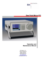
2.5 Display options
The HMT370EX transmitter can be ordered either with a graphical LCD display, or alternatively
without a display. The display options are shown in Figure 1 (page 11).
2
1
Figure 1 HMT370EX transmitter display options
1
Transmitter with display: LCD display with 4-button interface
2 Transmitter without display: LED status indicator
Chapter 2 – Product overview
11

In the display model, probe and transmitter configuration can be carried out either using the
4-button interface of the display, or by connecting the probe or transmitter to Vaisala Insight
PC software. In the model without display, all configuration must be carried out with Vaisala
Insight PC software.
For information on Vaisala Insight PC software, see Vaisala Insight PC software (page 55).
For information on the display interface, see Local display overview (page 46).
2.5.1 LED states in transmitter with no display
In the transmitter model with no display, the status LED indicator on the front of the
transmitter provides a visual indication of the transmitter's status. If the transmitter LED status
indicates that notifications or error messages exist, connect to Vaisala Insight PC software to
view status information and carry out any required configuration.
For instructions on connecting to Insight, see Connecting to Insight PC software (page 55).
For an overview of the Insight software, see Vaisala Insight PC software (page 55).
Table 5 LED status indicator states
LED color Meaning
Not lit Power o.
Green, fast blinking Starting up.
Green, not blinking Power on, normal measurement.
Green, slow blinking Notification or warning, normal measurement. Connect to Insight
to view status information and configure.
Red Error. Connect to Insight to view status information and
configure.
Red and blinking Critical error. Connect to Insight to view status information and
configure.
2.6 Connectivity to Vaisala Insight software
The HMT370EX transmitter and HMT370EX series probes can be connected to Vaisala Insight
software either together as one unit or separately with a Vaisala USB cable (see Spare parts
and accessories (page 93)). With the Insight software, you can:
• Calibrate and adjust the measurement.
• Test and adjust the analog outputs.
• Configure analog output parameter selection, scaling, error, and clipping settings.
• Configure environmental compensations, measurement settings, and local display
settings.
• View real-time measurements and device and status information.
HMT370EX User Guide M212305EN-A
12

More information
‣
Connecting to Insight PC software (page 55)
2.7 Transmitter parts
The external parts of the transmitter are shown in Figure 2 (page 13), and the internal parts of
the transmitter are shown in Figure 3 (page 14).
1 2
3
10
7
54
9
8
6
Figure 2 HMT370EX transmitter external parts
1
Detachable probe body
2 Transmitter body (for internal parts, see Figure 3 (page 14))
3 Graphical LCD display (see Display options (page 11))
4 Display interface buttons (see Local display overview (page 46))
5 Wall pads (4 pcs)
6 Retrofit mounting plate for replacing HMT360 installations (optional)
7 Probe body locking wheel
8 Probe head (for information on dierent probe options, see HMT370EX probe options
overview (page 21))
9 Grounding terminal
10 Lead-throughs for wiring (for lead-through accessory options, see Cable gland and
conduit options (page 14))
Chapter 2 – Product overview
13

2
mA
Test Points
CH1
CH2
mA
V
V
2a
2b
3 4
1
5
Figure 3 HMT370EX transmitter internal parts
1
Holes for mounting screws
2 Screw terminals and output test points: see 2a and 2b
2a Analog output channel 1 and 2 multimeter test points for current and voltage
2b Screw terminals for wiring analog output channels 1 and 2
3 Cable fastening clamps
4 Transmitter grounding terminal
5 Transmitter service port (M8, requires Vaisala USB cable accessory)
2.7.1 Cable gland and conduit options
The HMT370EX transmitter body has two M20x1.5 lead-throughs that can be fitted with cable
glands, conduit fittings, and plugs, as required by your application. By default, the transmitter
comes delivered with 2 dierent plug types on the transmitter lead-throughs as shown in
Figure 4 (page 15).
HMT370EX User Guide M212305EN-A
14

1
2
Figure 4 Default plugs in HMT370EX lead-throughs
1 Removable plastic transport cover: must be replaced (fold sides of transport cover
together and pull out)
2 Metal sealing plug: can be used in final installation
The plastic transport cover (1) must always be replaced with an Ex compliant cable gland,
conduit, or seal when wiring HTM370EX. The metal sealing plug (2) can be left in place and
used in the final installation, if the right-hand lead-through is not used.
Cable glands, conduits, and plugs are available from Vaisala as accessories (listed in Table 6
(page 15)).
Table 6 Cable lead-through accessories
Accessory Vaisala item code
Cable gland M20 x 1.5 for Ø 5 … 11 mm cable 265207SP
Cable gland M20 x 1.5 for Ø 10 … 14 mm cable 265208SP
Conduit fitting M16 265243SP
Conduit fitting NPT1/2" 265240SP
Dummy plug (Ex, 2 pcs) 254931SP
If you use lead-through accessories not ordered from Vaisala, note
the following requirements:
• The cable glands and cables used for wiring the device must not impair the Ex
protection.
• Unused lead-throughs must be sealed using Ex compliant plugs.
• The glands and plugs must be water and dust tight (minimum IP rating: IP54).
CAUTION!
Chapter 2 – Product overview
15

2.8 Using HTM370EX Series transmitters in
hazardous locations
Protected installation using galvanic isolators or Zener barriers is
mandatory in a hazardous environment.
WARNING!
In hazardous environments, always connect the transmitters via galvanic isolators or Zener
barriers. A galvanic isolator or Zener barrier must also be used when the transmitter and probe
body are in a safe area, but the probe head is installed in a hazardous environment. For wiring
information, see the galvanic isolator and Zener barrier wiring diagrams included in this
document.
HMT370EX does not include a galvanic isolator or a Zener barrier. They can be ordered as
optional accessories from Vaisala.
HMT370EX series transmitters have been designed for use in
hazardous locations as specified by the product classification. The personnel
installing, using, or maintaining HMT370EX transmitters are responsible for
determining the appropriate protection concept for the specific application
HMT370EX is used in, and that the hazardous area classification of the device
meets the requirements of the application.
WARNING!
If the equipment is used in a manner not specified by Vaisala, the
protection provided by the equipment may be impaired.
WARNING!
HMT370EX series transmitters are certified for use in hazardous areas as defined by the
following classifications:
Table 7 HMT370EX series hazardous area classifications
Certification HMT370EX classification
IECEx
1)
/ ATEX
2)
II 1 G Ex ia IIC T4 Ga
II 1 D Ex ia IIIC T
200
85 °C Da
-40 °C ≤ T
amb
≤ +60 °C
1) International certification
2) EU certification
HMT370EX User Guide M212305EN-A
16

The personnel installing, operating, and maintaining HMT370EX
transmitters must have the required competencies for working in the hazardous
location, as defined by the applicable standards.
CAUTION!
For information on the standards that apply to using HMT370EX based on the classification of
the device, see HMT370EX certification documentation and the declarations of conformity
related to HMT370EX at www.vaisala.com/declarationofconformity.
2.8.1 Guidelines for safe use in hazardous conditions
HMT370EX Series parts overview
HMT370EX
1 2 31a
M20x1.5 M20x1.5
Figure 5 HMT370EX parts overview
HMT370EX Series transmitters consist of 3 main parts: the transmitter body, a detachable
probe body, and a probe head attached to the probe body, either directly or using a cable.
Figure 5 (page 17) shows the main parts.
1
Probe heads (for variant descriptions, see HMT370EX User Guide)
1a Probe head filters
2 Probe body
3 Transmitter body
Chapter 2 – Product overview
17

The dierent probe head variants are designed for a range of applications, and have their own
specifications. Ensure that the transmitter body, probe body, and probe head are each placed
in an environment that matches the specification of the part. For allowed ambient temperature
ranges, see Table 8 (page 18).
Table 8 Allowed ambient temperature ranges
Equipment part Allowed ambient temperature range
Transmitter body -40 °C … +60 °C (-40 … +140 °F)
Probe body -40 °C … +60 °C (-40 … +140 °F)
Probe heads HMP374, HMP375, HMP377, and
HMP378
Temperature class T4:
-70 °C … +120 °C (-94 … +248 °F)
Temperature class T3:
-70 °C … +180 °C (-94 … +356 °F)
Probe head HMP371 Temperature class T4:
-40 °C … +60 °C (-40 … +140 °F)
Probe head HMP373 Temperature class T4:
Rubber cable version:
-40 °C … +80 °C (-40 … +176 °F)
FEP cable version:
-40 °C … +120 °C (-40 … +248 °F)
2.8.1.1 Specific conditions of use
With the installation of the equipment in Zone 0 Group II area it has
to be ensured that sparks due to impact or friction do not occur.
CAUTION!
Wiring requirements
• The cable glands and cables used for wiring the device must not impair the Ex protection.
• Unused lead-throughs must be sealed using Ex compliant plugs.
• Select a strain relief option that suits the application (either use cable glands that include
strain relief or install separate clamps: see IEC 60079-14).
Connect only de-energized wires. Never switch on the power supply
input before completing the wiring and closing the transmitter body.
CAUTION!
HMT370EX User Guide M212305EN-A
18
/