Page is loading ...

M212287EN-C
User Guide
Indigo 500 Series Transmitters
Indigo 520

PUBLISHED BY
Vaisala Oyj
Vanha Nurmijärventie 21, FI-01670 Vantaa, Finland
P.O. Box 26, FI-00421 Helsinki, Finland
+358 9 8949 1
Visit our Internet pages at www.vaisala.com.
© Vaisala 2020
No part of this document may be
reproduced, published or publicly
displayed in any form or by any means,
electronic or mechanical (including
photocopying), nor may its contents be
modified, translated, adapted, sold or
disclosed to a third party without prior
written permission of the copyright holder.
Translated documents and translated
portions of multilingual documents are
based on the original English versions. In
ambiguous cases, the English versions are
applicable, not the translations.
The contents of this document are subject
to change without prior notice.
Local rules and regulations may vary and
they shall take precedence over the
information contained in this document.
Vaisala makes no representations on this
document’s compliance with the local
rules and regulations applicable at any
given time, and hereby disclaims any and
all responsibilities related thereto.
This document does not create any legally
binding obligations for Vaisala towards
customers or end users. All legally binding
obligations and agreements are included
exclusively in the applicable supply
contract or the General Conditions of Sale
and General Conditions of Service of
Vaisala.
This product contains software developed
by Vaisala or third parties. Use of the
software is governed by license terms and
conditions included in the applicable
supply contract or, in the absence of
separate license terms and conditions, by
the General License Conditions of Vaisala
Group.
This product may contain open source
software (OSS) components. In the event
this product contains OSS components,
then such OSS is governed by the terms
and conditions of the applicable OSS
licenses, and you are bound by the terms
and conditions of such licenses in
connection with your use and distribution
of the OSS in this product. Applicable OSS
licenses are included in the product itself
or provided to you on any other applicable
media, depending on each individual
product and the product items delivered
to you.

Table of contents
1. About this document.....................................................................................7
1.1 Version information.......................................................................................... 7
1.2 Related manuals................................................................................................7
1.3 Documentation conventions............................................................................7
1.4 Trademarks........................................................................................................ 8
2. Product overview............................................................................................9
2.1 Introduction to Indigo 500 Series Transmitters............................................9
2.1.1 Probe compatibility...................................................................................9
2.2 Indigo 520 basic features and options...........................................................9
2.3 Indigo 520 transmitter parts..........................................................................10
2.3.1 Cable gland and conduit options...........................................................10
2.4 Touchscreen display......................................................................................... 11
2.5 Web interface...................................................................................................12
2.6 Output options.................................................................................................12
2.6.1 Analog outputs.........................................................................................12
2.6.2 Digital output............................................................................................13
2.6.3 Relays.........................................................................................................13
2.7 Ethernet connection........................................................................................13
2.8 Safety................................................................................................................14
2.8.1 ESD protection..........................................................................................15
2.9 Regulatory compliances................................................................................. 15
2.9.1 FCC Part 15 compliance statement........................................................ 15
2.9.2 Canada ICES-003 compliance statement............................................. 16
3. Installation........................................................................................................ 17
3.1 Opening and closing transmitter cover........................................................ 17
3.2 Mounting...........................................................................................................17
3.2.1 Standard wall mounting.......................................................................... 18
3.2.2 Wall mounting with adapter plate......................................................... 19
3.2.3 DIN rail mounting....................................................................................20
3.2.4 Pole mounting.......................................................................................... 21
3.3 Wiring...............................................................................................................23
3.3.1 Power supply terminals and lead-through − PELV option................. 23
3.3.2 Power supply terminals and lead-through − AC (mains)
power option........................................................................................... 24
3.3.3 Relay output terminals and lead-through............................................25
3.3.4 Analog output terminals and lead-through.........................................26
3.3.5 Ethernet connector and lead-through..................................................27
3.3.6 Probe connection terminals and lead-throughs..................................28
3.3.7 Verifying tightness of cable glands.......................................................29
3.4 Attaching probes............................................................................................29
4. User interfaces................................................................................................ 31
4.1 Touchscreen display and main views............................................................ 31
4.2 Web interface and main views......................................................................33
Table of contents
1

5. Start-up.............................................................................................................34
5.1 Starting up transmitter using touchscreen display....................................34
5.1.1 Configuring network connection on touchscreen...............................35
5.1.2 Setting date and time on touchscreen................................................. 37
5.2 Starting up transmitter using web interface............................................... 38
5.2.1 Connecting to web interface................................................................. 39
5.2.2 Creating web interface users................................................................ 40
5.2.3 Logging in to web interface...................................................................42
5.2.4 Changing language in web interface....................................................42
5.2.5 Configuring network connection in web interface............................. 43
5.2.6 Setting date and time in web interface................................................45
6. Configuring transmitter using touchscreen display.......................47
6.1 Accessing configuration menu..................................................................... 47
6.2 Configuring home views on touchscreen....................................................48
6.3 Configuring analog outputs on touchscreen..............................................49
6.3.1 Analog output configuration example..................................................52
6.4 Configuring relays on touchscreen...............................................................52
6.4.1 Relay configuration example.................................................................54
6.4.2 Relay wiring and relay activation mode...............................................54
6.4.3 Relay hysteresis....................................................................................... 55
6.5 Enabling Modbus TCP/IP on touchscreen................................................... 55
6.6 Enabling temperature compensation on touchscreen.............................. 55
7. Configuring transmitter using web interface.................................... 57
7.1 Configuring web interface home view.........................................................57
7.2 Configuring analog outputs in web interface............................................. 58
7.3 Configuring relays in web interface............................................................. 59
7.4 Enabling Modbus TCP/IP in web interface................................................... 61
7.5 Enabling temperature compensation in web interface............................. 62
8. Modbus............................................................................................................. 63
8.1 Modbus overview........................................................................................... 63
8.2 Unit identification of transmitter and probes............................................. 63
9. Maintenance and troubleshooting.........................................................65
9.1 Cleaning...........................................................................................................65
9.2 Replacing probes............................................................................................65
9.3 Updating transmitter software version....................................................... 66
9.4 Restoring factory default settings................................................................68
9.5 Troubleshooting............................................................................................. 69
10. Technical data................................................................................................ 72
10.1 Specifications..................................................................................................72
10.2 Compatible probes and devices................................................................... 74
10.3 Spare parts and accessories..........................................................................74
Appendix A:
Modbus reference.................................................................. 76
A.1 Unit IDs.............................................................................................................76
Indigo 520 User Guide M212287EN-C
2

A.2 Function codes................................................................................................76
A.3 Device identification objects.........................................................................76
A.4 Modbus communication examples...............................................................78
Maintenance and calibration......................................................................... 81
Warranty.............................................................................................................81
Technical support.............................................................................................81
Recycling............................................................................................................81
Table of contents
3

List of figures
Figure 1 Indigo 520 cable gland and conduit options, example
configurations.................................................................................................... 11
Figure 2 Standard wall mounting.................................................................................18
Figure 3 Transmitter mounting dimensions.............................................................. 18
Figure 4 Wall mounting with adapter plate.............................................................. 19
Figure 5 Adapter plate dimensions............................................................................ 20
Figure 6 Attaching DIN rail clip fasteners.................................................................. 21
Figure 7 Attaching mounting plate to fixing brackets - vertical
pole mounting..................................................................................................22
Figure 8 Attaching transmitter to mounting plate - vertical pole
mounting........................................................................................................... 22
Figure 9 Example of stripped AC (mains) power cable........................................ 25
Figure 10 M20×1.5 cable gland with split bushing....................................................28
Figure 11 Attaching probes to transmitter using probe cable connector.........30
Figure 12 Measurements (Home) view on touchscreen.......................................... 31
Figure 13 Configuration menu on touchscreen......................................................... 32
Figure 14 Web interface and main views.................................................................... 33
Figure 15 Network settings on touchscreen.............................................................. 36
Figure 16 Date and time settings on touchscreen.................................................... 37
Figure 17 Web interface, Measurements (Home) view...........................................39
Figure 18 User creation page.........................................................................................40
Figure 19 Network settings in web interface.............................................................44
Figure 20 Date and time settings in web interface...................................................45
Figure 21 Configurable Home views on touchscreen..............................................48
Figure 22 Analog outputs configuration menu on touchscreen,
General tab active...........................................................................................50
Figure 23 Relays configuration menu on touchscreen, Relay 2 tab active........ 53
Figure 24 Behavior of relay that activates above limit, with hysteresis..............55
Figure 25 Analog outputs configuration menu in web interface..........................58
Figure 26 Relays configuration menu in web interface...........................................60
Indigo 520 User Guide M212287EN-C
4

List of tables
Table 1 Document versions (English)...........................................................................7
Table 2 Related manuals...................................................................................................7
Table 3 PELV power supply input terminals.............................................................24
Table 4 AC power supply input terminals................................................................. 25
Table 5 Output terminals for relay 1 and relay 2......................................................26
Table 6 Analog output terminals................................................................................. 27
Table 7 Connection terminals for probe 1 and probe 2......................................... 29
Table 8 Relay wiring: Normally open (NO)...............................................................54
Table 9 Relay wiring: Normally closed (NC).............................................................54
Table 10 Unit IDs of transmitter and probes...............................................................63
Table 11 Transmitter options...........................................................................................72
Table 12 Operating environment................................................................................... 72
Table 13 Inputs and outputs............................................................................................72
Table 14 Compliance......................................................................................................... 73
Table 15 Mechanical specifications............................................................................... 73
Table 16 Compatible Indigo smart probes.................................................................. 74
Table 17 Accessories......................................................................................................... 74
Table 18 Spare parts..........................................................................................................75
Table 19 Unit IDs of transmitter and probes...............................................................76
Table 20 Modbus function codes................................................................................... 76
Table 21 Device identification objects..........................................................................76
List of tables
5

Indigo 520 User Guide M212287EN-C
6

1. About this document
1.1 Version information
This document provides detailed instructions for installing, using, and maintaining Vaisala
Indigo 520 transmitters.
Table 1 Document versions (English)
Document code Date Description
M212287EN-C September
2020
Added sections:
• Enabling temperature compensation on touchscreen
(page 55)
• Enabling temperature compensation in web interface
(page 62)
M212287EN-B August 2020 Added sections:
• Compatible probes and devices (page 74)
Updated sections:
• Updating transmitter software version (page 66)
M212287EN-A May 2020 First version.
1.2 Related manuals
Table 2 Related manuals
Document code Name
M212290EN Indigo 520 Quick Guide
1.3 Documentation conventions
Warning alerts you to a serious hazard. If you do not read and
follow instructions carefully at this point, there is a risk of injury or even death.
WARNING!
Chapter 1 – About this document
7

Caution warns you of a potential hazard. If you do not read and
follow instructions carefully at this point, the product could be damaged or
important data could be lost.
CAUTION!
Note highlights important information on using the product.
Tip gives information for using the product more eciently.
Lists tools needed to perform the task.
Indicates that you need to take some notes during the task.
1.4 Trademarks
Vaisalaâ is a registered trademark of Vaisala Oyj.
Modbusâ is a registered trademark of Schneider Automation Inc.
Microsoftâ, Windowsâ, Internet Explorerâ, and Edge
™
are either registered trademarks or
trademarks of Microsoft Corporation in the United States and/or other countries.
All other product or company names that may be mentioned in this publication are trade
names, trademarks, or registered trademarks of their respective owners.
Indigo 520 User Guide M212287EN-C
8

2. Product overview
2.1 Introduction to Indigo 500 Series Transmitters
Vaisala Indigo 500 Series Transmitters are industrial-grade, robust transmitters that
accommodate 1 or 2 Vaisala Indigo compatible probes for humidity, temperature, dew point,
carbon dioxide, hydrogen peroxide, and moisture in oil measurements. The transmitters can
display measurements on the spot as well as transmit them to automation systems through
analog signals, relays, or Modbus TCP/IP protocol.
The Indigo 520 transmitter has 2 probe connections and a touchscreen display.
For more information on Indigo 500 transmitter models, see www.vaisala.com/indigo.
2.1.1 Probe compatibility
Vaisala Indigo 500 Series Transmitters are the most versatile option for use with Indigo
compatible smart probes such as:
• Humidity and temperature probes: HMP3, HMP4, HMP5, HMP7, HMP8, HMP9, and TMP1
• Dew point probes: DMP5, DMP6, DMP7, DMP8
• CO
2
probes: GMP251, GMP252
• Vaporized hydrogen peroxide probes: HPP271, HPP272
• MMP8 moisture in oil probe
2.2
Indigo 520 basic features and options
• Universal transmitter for Vaisala Indigo compatible probes
• Supports 2 detachable probes simultaneously
• Touchscreen display for real-time data viewing and configuration
• IP66 and NEMA 4 rated metal enclosure
• 4 configurable analog outputs (not available with PoE option)
• 2 configurable relays (not available with PoE option)
• Ethernet connection with web interface for remote access
• Modbus TCP/IP protocol
• Installation options:
• Wall mounting
• Wall mounting with adapter plate (retrofit to replace Vaisala 330 series transmitters
such as HMT330)
• DIN rail with adapter
• Pole mounting
• Power supply options:
• Protective extra-low voltage (PELV) version: 15 … 35 VDC, 24 VAC ±20 %
• AC (mains) power version: 100 … 240 VAC 50/60 Hz
• Power over Ethernet (PoE) version: 50 VDC PoE+, IEEE 802.3at PD
Chapter 2 – Product overview
9

2.3 Indigo 520 transmitter parts
1
3
4
2
7
6
5
1 Touchscreen display
2 Transmitter base
3 Transmitter cover
4 Cable gland for Ethernet cable and optional analog output cable (M20×1.5 lead-through)
5 Cable glands for probe connection cables (M16×1.5 lead-throughs)
6 Cable gland for optional relay cable and power cable in the PELV and AC (mains) power
supply options (M20×1.5 lead-through)
7 Allen screws for opening the cover
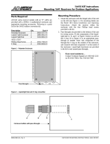
2.3.1 Cable gland and conduit options
The transmitter has 4 lead-throughs. The glands or conduit fittings for the lead-throughs are
selected when ordering the transmitter. Unused lead-throughs are plugged.
The following figure shows examples of dierent cable gland and conduit configurations
available from Vaisala.
Indigo 520 User Guide M212287EN-C
10

3
2
2 1
4
2
2 1
1
2
2 1
Figure 1 Indigo 520 cable gland and conduit
options, example configurations
1 Cable gland, M20×1.5
2 Cable gland, M16×1.5
3 Cable gland with split bushing,
M20×1.5
4 Conduit fitting, M20×1.5 for NPT1/2"
conduit
More information
‣
Spare parts and accessories (page 74)
2.4
Touchscreen display
You can configure the transmitter's capacitive touchscreen display to show numeric readings
of 1 … 4 measurement parameters at the same time, as well as graphs for 1 … 2 parameters. You
can also configure the transmitter outputs and other transmitter settings.
The touchscreen display also shows the status of the analog and digital outputs and relays.
The display window is made of chemically strengthened glass.
Chapter 2 – Product overview
11

More information
‣
Touchscreen display and main views (page 31)
‣
Starting up transmitter using touchscreen display (page 34)
2.5 Web interface
The transmitter also has a web interface for remote access. You can configure the web
interface to show numeric readings and graphs of 1 … 6 measurement parameters at the same
time. You can also configure the transmitter outputs and other transmitter settings, and
update the transmitter software.
The web interface has 2 user levels:
• Administrator: Configuration rights. Can configure outputs and change transmitter
settings.
• Guest: View-only access. Can add and remove measurement parameters in the
Measurements view.
The web interface supports most major browsers (for example, Firefox, Chrome, and Safari):
using the most recent version is recommended.
More information
‣
Web interface and main views (page 33)
‣
Starting up transmitter using web interface (page 38)
‣
Updating transmitter software version (page 66)
2.6
Output options
The transmitter provides 4 analog output channels, 2 relays, and an Ethernet connection for
the Modbus TCP/IP protocol and web interface.
If the transmitter is powered using Power over Ethernet (PoE), analog outputs
and relays are not available.
2.6.1 Analog outputs
The transmitter provides 4 scalable analog output channels with voltage or current output.
Available analog output modes:
• Voltage: 0 … 1 V, 0 … 5 V, 0 … 10 V
• Current: 4 … 20 mA, 0 … 20 mA
Use the touchscreen or web interface to configure the output mode for the channels (same
output mode in all channels), as well as the measurement parameter and scaling for each
channel.
Indigo 520 User Guide M212287EN-C
12

Analog outputs are not available in transmitters that are powered with Power
over Ethernet (PoE).
More information
‣
Configuring analog outputs on touchscreen (page 49)
‣
Configuring analog outputs in web interface (page 58)
2.6.2 Digital output
The transmitter supports the Modbus TCP/IP communication protocol (over Ethernet).
More information
‣
Enabling Modbus TCP/IP on touchscreen (page 55)
‣
Enabling Modbus TCP/IP in web interface (page 61)
2.6.3 Relays
The transmitter provides 2 configurable relays that can be wired either as normally closed or
as normally open. Use the touchscreen or web interface to configure the relay activation
parameters.
Relays are not available in transmitters that are powered with Power over
Ethernet (PoE).
More information
‣
Configuring relays on touchscreen (page 52)
‣
Configuring relays in web interface (page 59)
2.7
Ethernet connection
The transmitter provides an Ethernet connection for the Modbus TCP/IP protocol and web
interface.
The transmitter's Ethernet interface can use both static and dynamic network settings. If you
configure the connection to use dynamic settings, the network where the Ethernet interface is
connected must have a DHCP server that provides the settings.
The transmitter's Ethernet interface is designed to be used in
trusted network environments (trusted corporate LAN or VPN-based connection
over the Internet). Avoid connecting the transmitter directly to a public network
because the device can be attacked by a malicious user through the network.
CAUTION!
Chapter 2 – Product overview
13

More information
‣
Configuring network connection on touchscreen (page 35)
‣
Configuring network connection in web interface (page 43)
2.8 Safety
Only licensed experts may install electrical components. They
must adhere to local and state legislation and regulations.
WARNING!
Make sure that you prepare and connect only de-energized wires.WARNING!
Transmitters powered with AC (mains) power must be connected
only to a grounded (earthed) power supply (class I equipment).
WARNING!
Only licensed experts may connect the AC (mains) power
connection to the power supply. A readily accessible disconnect device must
be incorporated in the fixed wiring.
WARNING!
Attach only Vaisala Indigo compatible probes to the transmitter.CAUTION!
Do not modify the unit or use it in ways not described in the
documentation. Improper modification or use may lead to safety hazards,
equipment damage, failure to perform according to specification, or decreased
equipment lifetime.
CAUTION!
The transmitter's Ethernet interface is designed to be used in
trusted network environments (trusted corporate LAN or VPN-based connection
over the Internet). Avoid connecting the transmitter directly to a public network
because the device can be attacked by a malicious user through the network.
CAUTION!
Indigo 520 User Guide M212287EN-C
14

A factory reset deletes all current settings of the device. After the
factory reset, you need to reconfigure the settings, including outputs and relays.
When you connect to the web interface the next time, you will be prompted to
give the activation code and create new users.
CAUTION!
2.8.1 ESD protection
Electrostatic Discharge (ESD) can damage electronic circuits. Vaisala products are adequately
protected against ESD for their intended use. However, it is possible to damage the product by
delivering electrostatic discharges when touching, removing, or inserting any objects in the
equipment housing.
To avoid delivering high static voltages to the product:
• Handle ESD‑sensitive components on a properly grounded and protected ESD workbench
or by grounding yourself to the equipment chassis with a wrist strap and a resistive
connection cord.
• If you are unable to take either precaution, touch a conductive part of the equipment
chassis with your other hand before touching ESD‑sensitive components.
• Hold component boards by the edges and avoid touching component contacts.
2.9
Regulatory compliances
This product complies with the following performance and environmental test standards:
This product is in compliance with the Australian RCM regulation and with the following
European Union directives:
• Low-voltage directive 2014/35
• EMC directive 2014/30
2.9.1 FCC Part 15 compliance statement
This equipment has been tested and found to comply with the limits for a Class B digital
device, pursuant to Part 15 of the FCC rules. These limits are designed to provide reasonable
protection against harmful interference in a residential installation. This equipment generates,
uses and can radiate radio frequency energy and, if not installed and used in accordance with
the instructions, may cause harmful interference to radio communications. However, there is
Chapter 2 – Product overview
15

no guarantee that the interference will not occur in a particular installation. If this equipment
does cause harmful interference to radio or television reception, which can be determined by
turning the equipment o and on, the user is encouraged to try to correct the interference by
one or more of the following measures:
• Reorient or relocate the receiving antenna.
• Increase the separation between the equipment and receiver.
• Connect the equipment into an outlet on a circuit dierent from that of the receiver.
• Consult the dealer or an experienced radio/TV technician for help.
Changes or modifications to this equipment not expressly approved
by the party responsible for compliance could void the user's authority to
operate the equipment.
CAUTION!
2.9.2 Canada ICES-003 compliance statement
This Class B digital apparatus complies with Canadian ICES‑003.
Cet appareil numerique de la classe B est conforme a la norme NMB‑003 du Canada.
Indigo 520 User Guide M212287EN-C
16

3. Installation
3.1 Opening and closing transmitter cover
Allen key (4 mm (5/32 in)), provided
1. Loosen the 2 allen screws on the transmitter cover.
2. Open the transmitter cover.
3. When you close the transmitter cover, tighten the allen screws to 4.5 Nm.
3.2
Mounting
Choose the location of the transmitter so that the power outlet is accessible.
Besides the standard wall mounting, the transmitter has the following mounting options:
• Wall mounting with adapter plate (retrofit to replace Vaisala 330 series transmitters such
as HMT330)
• DIN rail mounting
• Pole mounting
Chapter 3 – Installation
17

3.2.1 Standard wall mounting
• Allen key (4 mm (5/32 in)),
provided
• Crosshead screwdriver
• Drill with Ø 8 mm drill bit
• Screws (2 pcs), provided
• Washers (2 pcs), provided
• Wall plugs (2 pcs), provided
Figure 2 Standard wall mounting
mm
[in]
[0.25]
Figure 3 Transmitter mounting dimensions
Indigo 520 User Guide M212287EN-C
18
/