Akai MPC2500 Owner's manual

Category
Recording Equipment
Type
Owner's manual

This manual is also suitable for

Operator's Manual
WARNING
To prevent fire or shock hazard,
do not expose this appliance to
rain or moisture.
Important Notice
The material in this document is copyright to AKAI professional M.I. Corp., and may not be
quoted or reproduced in any form without written permission from the company.
LIMITED SOFTWARE WARRANTY POLICY
All the software provided with, or purchased especially for, AKAI professional products has
been tested for functionality. AKAI professional M.I. Corp. will make its best efforts to correct
reported software defects for future releases subject to technical practicabilities.
AKAI professional M.I. Corp. makes no warranty or representation either expressed or
implied with respect to the system's performance or fitness for a particular purpose.
In no event will AKAI professional M.I. Corp. be liable for direct or indirect damages arising
from any defect in the software or its documentation. Further, AKAI professional M.I. Corp.
will not accept any liability for any programs, sounds, audio recording or sequences stored in
or used with AKAI professional products, including the cost of recovery of such data.
The warranties, remedies and disclaimers above are exclusive and take precedence over all
others, oral or written, express or implied, to the extent permitted by law in the geographical
area of the product's use. No employee of AKAI professional M.I. Corp., agent, distributor or
employee of an agent or distributor is authorised to offer any variation from this policy.
WARNING!!
To prevent fire or shock hazard, do not expose this appliance to rain or moisture.
1-En
DO NOT REMOVE COVER (OR BACK).
NO USER-SERVICEABLE PARTS INSIDE.
REFER SERVICING TO QUALIFIED SERVICE PERSONNEL.
CAUTION
DO NOT OPEN
CAUTION: TO REDUCE THE RISK OF ELECTRIC SHOCK
RISK OF ELECTRIC SHOCK
THE SYMBOLS ARE RULED BY UL STANDARDS (U.S.A.)
The lightning flash with arrowhead symbol, within an equilateral triangle, is
intended to alert the user to the presence of uninsulated “dangerous voltage”
within the product’s enclosure; that may be of sufficient magnitude to
constitute a risk of electric shock to persons.
The exclamation point within an equilateral triangle is intented to alert the user
to the presence of important operating and maintenance (servicing) instruc-
tions in the literature accompanying the appliance.
5B-En
.
.
.
Caution - use of controls or adjustments or performance of procedures
other than those specified herein may result in hazardous radiation exposure.
June - 8 / 2005 Rev.1
.
This appliance is not equipped with a fully disconnect main power switch. Even when the appliance
is turned off, the power supply to the appliance is not completely turned off when the power cord is
plugged in. Pull out the power cord when not using the appliance for long periods.
WARNING: WHEN USING ELECTRIC PRODUCTS, BASIC PRECAUTIONS SHOULD ALWAYS
BE FOLLOWED, INCLUDING THE FOLLOWING:
WARNING
The MPC2500 is designed to be used in a standard household environment.
Power requirements for electrical equipment vary from area to area. Please ensure that your MPC2500
meets the power requirements in your area. If in doubt, consult a qualified electrician or AKAI profes-
sional dealer.
120 VAC @ 60 Hz for USA and Canada
220~240 VAC @ 50 Hz for Europe
240 VAC @ 50 Hz for Australia
IMPORTANT SAFETY INSTRUCTIONS
1. Read these instructions.
2. Keep these instructions.
3. Heed all warnings.
4. Follow all instructions.
5. Do not use this apparatus near water.
6. Clean only with dry cloth.
7. Do not block any ventilation openings. Install in accordance with the manufacture's instructions.
8. Do not install near any heat souces such as radiators, heat register, stoves, or other apparatus
(including amplifiers) that produce heat.
9. Do not defeat the safety purpose of the polarized or grounding-type plug. A polarized plug has
two blades with one wider than the other. A grounding type plug has two blades and a third
grounding prong. The wide blade or the third prong are provided for your safety. If the provided
plug does not fit into your outlet, consult an electrician for replacement of the obsolete outlet.
10. Protect the power cord from being walked on or pinched particularly at plugs, convenience
receptacles, and the point where they exit from the apparatus.
11. Only use attachments/accessories specified by the manufacturer.
12. Use only with the cart, stand, tripod, bracket, or table specified by the manufacturer, or sold
with the apparatus. When a cart is used, use caution when moving the cart/apparatus combin-
ation to avoid injury from tip-over.
13. Unplug this apparatus during lightning storms or when unused for long periods of time.
14. Refer all servicing to qualified service personnel. Servicing is required when the apparatus has
been damaged in any way, such as power-supply cord or plug is damaged, liquid has been
spilled or objects have fallen into the apparatus, the apparatus has been exposed to rain or
moisture, does not operate normally, or has been dropped.
15. Do not expose this apparatus to dripping or splashing and ensure that no objects filled with
liquids, such as vases, are placed on the apparatus.
For U.K. customers only
WARNING
THIS APPARATUS MUST BE EARTHED
IMPORTANT
This equipment is fitted with an approved non-rewireable UK mains plug.
To change the fuse in this type of plug proceed as follows:
1) Remove the fuse cover and old fuse.
2) Fit a new fuse which should be a BS1362 5 Amp A.S.T.A or BSI approved type.
3) Refit the fuse cover.
If the AC mains plug fitted to the lead supplied with this equipment is not suitable for your type of
AC outlet sockets, it should be changed to an AC mains lead, complete with moulded plug, to the
appropriate type. If this is not possible, the plug should be cut off and a correct one fitted to suit the
AC outlet. This should be fused at 5 Amps.
If a plug without a fuse is used, the fuse at the distribution board should NOT BE GREATER than
5 Amp.
PLEASE NOTE: THE SEVERED PLUG MUST BE DESTROYED TO AVOID A POSSIBLE
SHOCK HAZARD SHOULD IT BE INSERTED INTO A 13 AMP SOCKET
ELSEWHERE.
The wires in this mains lead are coloured in accordance with the following code:
GREEN and YELLOW Earth
BLUE Neutral
BROWN Live
As the colours of the wires in the mains lead of this apparatus may not correspond with the coloured
markings identifying the terminals in your plug, please proceed as follows:
The wire which is coloured GREEN and YELLOW must be connected to the terminal which is
marked with the letter E or with the safety earth symbol or coloured GREEN or coloured
GREEN and YELLOW.
The wire which is coloured BLUE must be connected to the terminal which is marked with the
letter N or coloured BLACK.
The wire which is coloured BROWN must be connected to the terminal which is marked with
the letter L or coloured RED.
THIS APPARATUS MUST BE EARTHED
Ensure that all the terminals are securely tightened and no loose strands of wire exist.
Before replacing the plug cover, make certain the cord grip is clamped over the outer sheath of the
lead and not simply over the wires.
6D-En
FCC WARNING
This equipment has been tested and found to comply with the limits for a Class B digital device
pursuant to Part 15 of the FCC rules. These limits are designed to provide reasonable protec-
tion against harmful interference in a residential installation. This equipment generates, uses,
and can radiate radio frequency energy and, if not installed and used in accordance with the
instructions, may cause harmful interference to radio communications. However, there is no
guarantee that interference will not occur in a particular installation. If this equipment does
cause harmful interference to radio or television reception, which can be determined by turn-
ing the equipment off and on, the user is encouraged to try to correct the interference by one
or more of the following measures:
Reorient or relocate the receiving antenna.
Increase the separation between the equipment and receiver.
Connect the equipment into an outlet on a circuit different from that to which the receiver is
connected.
Consult the dealer or an experienced radio/TV technician for help.
21B-En
AVIS POUR LES ACHETEURS CANADIENS DU MPC2500
Le présent appareil numérique n’ément pas de bruits radioélectriques dépassant les limites
applicables aux appareils numériques de la Class B prescrites dans le Règlement sur le
brouillage radioélectrique édicté par le ministère des Communications du Canada.
27-F
This digital apparatus does not exceed the Class B limits for radio noise emissions from digital
apparatus set out in the Radio Interference Regulations of the Canadian Department of Com-
munications.
27-En
VENTILATION
Do not prevent the units ventilation, especially by placing the unit on soft carpet, in a narrow
space, or by placing objects on the units chassistop, side, or rear panels. Always keep the
units chassis at least 10 centimeters from any other objects.
31C-En
CHANGES OR MODIFICATIONS NOT EXPRESSLY APPROVED BY THE MANUFACTURER
FOR COMPLIANCE COULD VOID THE USERS AUTHORITY TO OPERATE THE EQUIP-
MENT.
32-En
COPYRIGHT NOTICE
The AKAI professional MPC2500 is a computer-based device, and as such contains and uses
software in ROMs. This software, and all related documentation, including this Operators Manual,
contain proprietary information which is protected by copyright laws. All rights are reserved. No
part of the software or its documentation may be copied, transferred or modified. You may not
modify, adapt, translate, lease, distribute, resell for profit or create derivative works based on the
software and its related documentation or any part thereof without prior written consent from
AKAI professional M.I. Corp., Yokohama, Japan.
MPC2500 Operators Manual rev 1.0
Table of contents
Table of contents
Chapter 1: Introduction 1
Overview ............................................................................................................1
Upper side of Top panel ..................................................................................... 1
DATA INPUT section .......................................................................................... 2
Control section ...................................................................................................3
Pad section ........................................................................................................ 3
Q-Link section ....................................................................................................4
Front Panel ........................................................................................................ 4
Rear Panel .........................................................................................................5
Connecting MPC2500 to External Audio / MIDI device ...................................... 6
Terminologies in MPC2500 ................................................................................ 7
Chapter 2: Basic Operation 9
Setting names ..................................................................................................10
Entering number with Numeric key .......................................................................11
Chapter 3: Sequencer feature 12
Recording the performance ..............................................................................13
Playing back a sequence ................................................................................. 14
Other useful features for recording sequences ............................................... 14
Detailed information on sequence features ......................................................18
Track feature ....................................................................................................21
MIDI sequencer feature ................................................................................... 24
Chapter 4: Editing sequences 26
Selecting a region within a track to edit ............................................................26
Selecting the editing region by bar ...................................................................29
Changing the order of tracks (TRACK MOVE) .................................................30
MPC2500 Operators Manual rev 1.0
Chapter 5: Step editing 31
About step edit .................................................................................................31
Screens ............................................................................................................31
Events ............................................................................................................. 32
Copying / Pasting an event ............................................................................. 35
Moving an event .............................................................................................. 35
Deleting an event ............................................................................................ 35
Entering an event(Step recording) .................................................................. 36
Chapter 6: Grid Edit 37
About Grid Edit ................................................................................................ 37
Screens ........................................................................................................... 37
Editing in GRID mode .................................................................................... 40
Copying(COPY) / Pasting(PASTE) an Event .................................................. 40
Moving (MOVE) an event ................................................................................ 40
Deleting an event ............................................................................................ 41
Entering an event ............................................................................................ 41
Chapter 7: Song mode 42
Structure of a song .......................................................................................... 42
Screens ........................................................................................................... 42
Creating a song ............................................................................................... 43
Playing a song ................................................................................................ 43
Other features in the SONG ............................................................................ 44
Chapter 8: Functions of a Pad 46
Playing with pads ............................................................................................... 46
Setting the track mute with pads ..................................................................... 47
Selecting a sequence to play with pads .......................................................... 48
Chapter 9: Q-Link slider & knob
Setting the slider & knob ................................................................................. 49
Recording the slider/knob value in a sequence ............................................... 50
AFTER key ...................................................................................................... 50
Other features Q-Link slider and knob ............................................................ 51
MPC2500 Operators Manual rev 1.0
Table of contents
Chapter 10: Using the MPC2500
with External devices 52
Sync with the MPC2500 as the master ........................................................... 52
Sync with the MPC2500 as the slave .............................................................. 52
Connecting the MPC2500 to the MIDI keyboard
with the sound module ................................. 53
Setting the MIDI input ..................................................................................... 53
Cutting off the internal sound from a pad (Setting Local Control) .................... 54
Changing sequence by Program Change from an external devices
..................... 54
Chapter 11: Recording a sample 55
Recording the sample - detailed information - .............................................. 57
Recording the digital signal ............................................................................. 57
Recording the MAIN OUT ............................................................................... 57
Recording the internal CD’s sound.................................................................. 58
Other features ................................................................................................. 59
Direct Recording feature .............................................................................. 60
Chapter 12: Editing a sample 63
Setting the start / end points for the samples .................................................. 63
Deleting an unnecessary part from a sample (DISCARD) .............................. 64
Deleting a selected range from sample and moving the data
after the end point towards the start point (DELETE) ....................... 64
Silencing a range selected from a sample(SILENCE) ..................................... 65
Saving part of a sample as a new sample (EXTRACT) ................................... 65
Sample widow feaures .................................................................................... 65
Other editing functions ................................................................................... 66
Dividing a phrase sample to several regions ............................................. 69
Dividing a sample by detecting the attack part of the phrase (AUTO) ..............70
Dividing a sample into regions of equal length (EQUALLY).............................. 71
Adjust the strart / end point of the region ........................................................ 72
Converting divided samples to
SLICED SAMPLE or PATCHED PHRASE ..................... 73
Converting PATCHED PHRASE ...................................................................... 73
Changing the tune and the tempo of a Patched phrase sample ..............................74
Editing a Patched Phrase ................................................................................ 74
Other available edits for Region .......................................................................75
MPC2500 Operators Manual rev 1.0
Setteing the loop ............................................................................................76
Linking the loop point to the start point ............................................................ 77
Auto Phrase Loop ............................................................................................ 77
Chapter 13: Program 78
Creating a program ..........................................................................................78
Assigning / Reassigning samples to the pads ..................................................78
Playing the sample while the Pad is being hit .................................................. 79
Setting the volume and the tuning for a sample ...............................................79
Changing the sample volume with velocity ...................................................... 79
Changing the sample pitch with velocity .......................................................... 80
Playing several samples with one pad ............................................................. 80
Switching between samples using velocity ...................................................... 80
Setting the envelope for a pad ......................................................................... 81
The functions in the Program window .............................................................. 83
Editing the sound of a sample ..........................................................................84
Limiting the number of the voicce in the Program ............................................85
Simulating the open / close hi-hat (setting the mute group) ............................. 86
Setting the overlap of the sounds on the same pad (voice overlap) .................86
Editing a pad sample ....................................................................................... 87
Setting a LFO (Low Frequency oscillator) ........................................................89
Delete all the unused samples at the same time (PURGE) .......................... 90
Setting a MIDI note number to the pads .......................................................... 90
Assigning MIDI note numbers to the pads (changing the default setting) ...........90
Chapter 14: Mixer 91
Setting the level and pan of the Pad ................................................................ 91
Setting the output for the sample ..................................................................... 91
Selecting the pad to apply the effect ................................................................92
Mixer Automation ............................................................................................. 92
Short cut between MIXER and Effect mode .....................................................93
Input Thru fuction .............................................................................................94
Applying effects to an incoming signal ............................................................. 94
Applying filters to an incoming signal ...............................................................95
Using Q-Link features in INPUT THRU mode .................................................. 95
Saving the setting of Input Thru ....................................................................... 96
MPC2500 Operators Manual rev 1.0
Table of contents
Chapter 15: Effect 97
Applying effects to a specific pad sound .......................................................... 97
Applying effects of the FX2 to the effect sound of the FX1 .............................. 98
Editing effects .................................................................................................. 98
Using the master effect .................................................................................. 101
Editing the master effect ................................................................................ 101
Editing the effect set ...................................................................................... 101
Short cut between MIXER and Effect mode ...................................................102
Chapter 16: Save / Load 103
About a memory card .....................................................................................103
Saving the data ..............................................................................................103
Saving data to the Internal Hard disk (option) ....................................... 106
Loading a file ..................................................................................................107
Renaming a file .............................................................................................. 110
Deleteing a file ............................................................................................... 110
Setting the auto load function .........................................................................110
Formatting the memory card .......................................................................... 111
Saving the data to the internal flash memory ................................................. 111
Chapter 17: Connecting the MPC2500
to your computer 112
Connecting the MPC2500 to a Windows - based PC ..................................... 112
Connecting the MPC2500 to the Macintosh ................................................... 112
Chapter 18: Other settings 114
Foot switch .....................................................................................................114
Adjusting the master level .............................................................................. 114
Adjusting the contrast of LCD .........................................................................114
Initialize to Factory Preset ..............................................................................114
Adjustment of Pad Sensitivity .........................................................................115
Continuous sample track ................................................................................116
Specifications ......................................... 117
Preset program list ..................................119
MIDI implementation chart ............................................................................. 120
Installation of Internal Hard Disk Drive ...........................................................122
Index .............................................................................................................. 123
MPC2500 Operator’s Manual rev 1.0
1
Chapter 1 : Introduction
01. Display
This is the LCD (Liquid Crystal Display) with back-
light. You can adjust the contrast of the LCD by
turning the DATA wheel while holding in the
[SHIFT] key.
02. [INPUT THRU] key
You can mix the Input signal of [RECORD IN] to the
Play-back sound from the MPC2500. For more infor-
mation, see the “INPUT THRU” feature on page 94.
03. [REC GAIN] knob:
It controls the recording level of the incoming sig-
nal from [RECORD IN]. It cannot control the digi-
tal input level.
04. [MAIN VOLUME] knob:
It controls the levels of [STEREO OUT] and
[PHONES] (headphone).
05. [F1] through [F6] keys:
These keys are used to call up pages at the bottom
of the display, or to execute the feature assigned to
the key. The available feature depends on the cur-
rently displayed screen.
Welcome to MUSIC PRODUCTION CENTER MPC2500. This operator's manual describes how to use an MPC2500.
Please read this manual before you start using your MPC2500, and keep it in a safe place so that you can refer to it as needed.
In this manual, the names of the knobs and keys on panels and plugs are located in square brackets, as follows: [name] .
06. PAD BANK [A] through [D] keys:
Use these keys to switch between pad banks A, B,
C, D. The LED above currently selected pad bank
will be lit.
07. [FULL LEVEL] key:
When turned on (LED is lit), the MPC2500 always
plays back at the maximum velocity (127).
08. [16 LEVELS] key:
When turned on, you can use 16 pads to change
the selected pad’s velocity and tune in 16 steps.
For more information, see the “16 Level function”
section on page 46.
09. [NEXT SEQ] key
This key calls up the NEXT SEQ page, where you
can switch sequences with pads. For more infor-
mation, see the ”Selecting the sequence to play with
pad” section on page 48.
10. [TRACK MUTE] key
This key calls up the TRACK MUTE page where
you can mute a track with pads. For more infor-
mation, see the “Selecting track mute with pads”
section on page 47.
Overview
This chapter describes the name of each part and the function, and explains how to make connections and terminologies for the MPC2500.
Upper-side of Top Panel
MPC2500 Operators Manual rev 1.0
2
Chapter 1: Introduction
DATA INPUT section
01. Numeric keys
These keys are used to enter numeric data directly.
Enter numbers with these keys into selected numeric
fields and press the [ENTER] key. If you are entering
numbers with a decimal value, enter the number ig-
noring the decimal point. (example: 120.5, enter
1205.). If you make a mistake, it is possible to cancel
by pressing the [SHIFT] key before the [ENTER] key.
If you use the [CURSOR] keys, [DATA] wheel, or
[MAIN] key while you are entering data with the nu-
meric keys, the input will be canceled and the data
returns to its original status.
02. [ - / + ] key
This key toggles a numeric value between (-) and (+).
03. [ENTER] key
This key finalizes the value that was input by the
numeric keys.
04. [DATA] wheel
This wheel changes the value of the currently se-
lected field. The data variably increases the faster
the wheel is turned. You can also adjust the con-
trast of the LCD by turning this wheel while hold-
ing in the [SHIFT] key.
05. [DATA] key ( [-] [+] keys)
[ - ]
key decreases the value of the highlighted cursor.
[ + ]
key increases the value of the highlighted cursor.
06. [MODE] key
When you press this key (LED will blink), you can
switch modes with pads.
07. [MAIN] key
Pressing this key displays MAIN mode, regardless
the current mode.
08. [WINDOW] key
Pressing this key, when the LED is lit, displays a
pop up window where you can make a detailed
setting of the field.
09. [TAP TEMPO] key
You can set a desired tempo by tapping this key. (
TAP TEMPO feature) For more information, see the
“Tap Tempo feature” section on page 18.
10. [SHIFT] key
You can use various features with a combination of
another key.
11. [UNDO] key
When you record a sequence, the LED of this key
will light up. Pressing this key, when the LED is lit,
resets the system to its status before recording, and
LED will be turned off.
12. [CURSOR] key
You can move the highlighted cursor up and down
on the screen to select a field. In the value field, you
can switch digits by pressing </> keys, holding
[SHIFT] key. This changes the value of the currently
selected field.
MPC2500 Operators Manual rev 1.0
3
Control section
01. [STEP] key (< / > )
This key locates the sequence point backwards and
forwards one step at a time. The step is set in the
Timing field of the MAIN screen. Pressing this key
while holding the [GO TO] key locates the position
of previous/next event recorded on a track.
02. [GO TO] key
This key displays the locate window. Entering the
locate point or moving the cursor to the memorized
locate point and then pressing [F5] (GO TO) locates
the position you want. To memorize a locate point,
pick a point that you want to memorize and display
the Locate window by pressing the GO TO key, then
move the cursor to the number you want to memo-
rize and press [F2] (CAPTUR) to memorize the point.
03. [BAR] key ( << / >>)
This key locates the sequence point by bars.
04. [REC] key
Pressing the [PLAY START] key or the [PLAY] key
holding this key starts recording to a sequence. Any
event that is already recorded on the track will be
replaced with new events. You can punch in by
pressing the [PLAY] + [REC] key while playing back
a sequence, and punch out by pressing the [REC]
key during recording. For more information, see the
“Punch In/Punch Out feature” section on page 17.
5. [OVER DUB] key:
This key is basically the same as the [REC] key, but
it adds new events to the current events (over dub).
You can punch in by pressing the [PLAY] + [OVER
DUB] keys while playing back a sequence, and
punch out by pressing the [OVER DUB] key while
over dubbing.
06. [STOP] key:
This key stops the play back/recording of a se-
quence. If you hit this key 3 times quickly, you can
stop all sound playing back.
07. [PLAY] key
This key starts the playback of a sequence from its
current position.
08. [PLAY START] key
This key starts the playback of a sequence from its
beginning.
PAD section
[PAD1] through [PAD16]
These are the drum pads to play the internal sam-
pler. The pressure/strength you use to hit the pad
controls the level of the sound. In TRACK MUTE
mode, you can select a track and, in NEXT SEQ mode,
you can select a sequence with a pad. You can also
use these pads to select modes or to enter letters.
MPC2500 Operators Manual rev 1.0
4
Chapter 1: Introduction
Q-Link section
01. [Q1] and [Q2] sliders
These sliders control the sound according to the setting in the SLIDER mode.
For more information, see the “Q-Link slider” section on page 49.
02. [Q3] and [Q4] knobs
These knobs control the sound according to the setting in the SLIDER mode. For more
information, see the “Q-Link slider” section on page 49.
03. [AFTER] key
When you turn on this key, the information of the Q-Link slider recorded on a track
replaces the current value of the slider. For more information, see page 50.
04. [ERASE] key
This key deletes event(s) within a track. You can delete events in real time on record-
ing, or you can select the events to delete in the Erase window. For more information,
see the “Erase feature” section on page 14.
05. [NOTE REPEAT] key
You can repeat a note according to the setting in T.C. (Timing Correct) by holding a
pad while pressing this key. For more information, see the “Note Repeat feature”
section on page 17.
Front Panel
01. CD Drive bay
You can install an optional IDE CD drive.
02. Compact flash slot:
This is a card slot for the compact flash memory card.
03. [FOOTSWITCH 1/2] plug:
This is where you connect a foot switch. You can use a foot switch to punch in/out. For more information, see the
“Foot Switch” section on page 114. There are two types of foot switches: normal open (the contact is open when it is
not pressed), and normal closed (the contact is closed when it is not pressed).
If a foot switch has been connected to the MPC2500, when you turn on the power to the MPC2500, it automatically
detects the type of foot switch connected. You can use either type of foot switch.
04. [PHONES] plug
This is a stereo phone plug to connect a set of headphones. It sends out the same signal with the [STEREO OUT] plug.
MPC2500 Operators Manual rev 1.0
5
Rear Panel
HOTCOLDGND
01. [DIGITAL IN/OUT] plug
These are the coaxial digital input/output. This IN
is to connect digital outputs such as a CD player
and a DAT. This OUT sends out the same signal as
the [STEREO OUT].
02. [STEREO OUT L/R] plug:
This is the main output
03. [USB] plug (slave)
You use this plug to connect the MPC2500 to your
PC and transfer data. For more information, see
the “Connecting the MPC2500 to your computer”
section on page 112.
04. [MIDI OUT A/B/C/D] plug
This is the MIDI output. Each output can send in-
dependent MIDI signals.
05. [MIDI IN 1/2] plug
This is the MIDI input. MIDI signals from MIDI
IN 1 and 2 will be merged (mixed).
06. [RECORD IN L/R] plug
This is an analog input for recording an analog sig-
nal. With a stereo phone plug, it can be used as
balanced input.
07. [ASSIGNABLE MIX OUT 1/2/3/4/5/6/7/8] plug
These are outputs you can use to output each pad
sound separately. With external mixers or effect-
ers, you can perform advanced mixing.
08. Power plug
Plug in the AC cable here.
09. [POWER] switch
It switches the power on/off of the unit.
MPC2500 Operators Manual rev 1.0
6
Chapter 1: Introduction
INPUT
Mixer
Amplifier
Monitor Speaker
INPUT
Sound Module
MIDI IN
AUDIO OUT
DJ Mixer
MASTER
OUT L / R
INPUT
PC or MAC
USB
MD Recorder
ALDIGIT IN
DIGITAL OUT
CD Player
MIDI Keyboard
MIDI OUT
Turn Table
PHONO
Microphone
Headphone
PHONES
FOOTSWITCH
12
Footswitch
Compact Flash
Connecting MPC2500 to External Audio/MIDI device
The diagram below demonstrates how you can connect the MPC2500 to an external Audio/MIDI device.
Please note that this is one example, so, when you actually connect your devices, refer to the device’s operator's manual.
Note: When you connect devices, make sure the power is turned off.
MPC2500 Operators Manual rev 1.0
7
Terminologies in MPC2500
These are the basic terminologies you need to know to operate the MPC2500:
Sequence
Sequence is the most basic unit that you use when you create data with
the MPC2500. The data from the MIDI keyboard or pads will be re-
corded to each track in a sequence.
A sequence has 64 tracks, each of which can hold performance data.
You can create up to 99 sequences. The length of a sequence can be set
from 1 bar to 999 bars. You can create a whole song with one sequence;
however you can also create a song with a combination of several short
sequences with the Song feature.
Track
A sequence has 64 tracks. Each track can record separate performance
data. For example, you can record instruments separately on each track
(ex. Piano sound in track 1, Bass on Track 2, Organ on Track 3,etc…).
You can record one track at a time; however, you can play back already-
recorded tracks while recording a new track. Each track has the track
mute setting (whether play back the contents of the track or not). For
example you record two Piano solos on Track 1 and Track4 and com-
pare them using mute function. Performance data will be recorded on a
track as a MIDI event. It does not record sounds directly on a track.
Song
With the song feature, you can play back sequences in a certain order.
You can set the order and number of sequences to play back freely. This
is useful when you wish to play back several songs in a row, or when
you are creating a song with a combination of several sequence data.
With the MPC2500, you can create up to 20 songs. When you arrange
sequences into a song, assign them to each step in the song. A step is like
a “container” of sequences. A song has 250 steps.
MPC2500 Operators Manual rev 1.0
8
Chapter 1: Introduction
Sample
With the MPC2500, sound data that is loaded into the unit is called a sample. A sample is loaded to the MPC2500 when
you record in RECORD mode, load from a memory card, or transfer from PC through USB. You can change the start/end
point of a sample or set loop in TRIM mode. To play back sounds, you need to assign samples to pads in PROGRAM
mode. There are 2 kinds of samples: Stereo sample (2-channel sample with left and right channels), and Mono sample (1-
channel sample).
Drum Pad
The MPC2500 has 16 pads. You can play a sample that is assigned to a pad by hitting the pad. The MPC2500 has 4 pad
banks that you can assign separate samples to. You can switch those 4 pad banks using the [PAD BANK] key, so you can
use up to 64 pads. To assign samples to the pads, use the PROGRAM mode. The performance of the pad can be recorded
to a track in a sequence.
Program
Once you assign samples to the pads in the PROGRAM mode, you can
play those samples with the pads. A set of 64 pads, each assigned
samples, is called the Program. The program also has features that al-
low you to control the sound of samples, such as envelop and filter. You
can make settings separately for each pad.
RAM
RAM (Random Access Memory) is a space where you can load sounds or data temporarily. The MPC2500 comes with 16
MB (megabyte) of RAM that can record up to 136 seconds (monaural recording). The MB is a unit that represents the size
of the memory. With the optional EXM128, you can increase your memory to 128MB.
The data loaded in the RAM will be deleted when you turn off the MPC2500. If you wish to save your recordings, you
need to save on a memory card, or transfer the data to PC through USB.
Memory Card
The MPC2500 has a 32MB compact flash memory card. Compact Flash is a memory that is called “Flash Memory” .You
can save the data on the flash memory like RAM, but the data will remain after you turn off the unit. By saving the
recordings in the MPC2500’s RAM on the Memory card, you can save the data after you turn off the MPC2500. Please
note that the MPC2500 cannot play back the data directly from a memory card. You have to load the data from a card to
RAM to play back. There are several kinds of flash memory cards, but MPC2500 uses “compact flash” memory cards.
MPC2500 Operator’s Manual rev 1.0
9
Chapter 2 : Basic Operation
In this chapter, we will describe the basic operation of the MPC2500.
MAIN Page
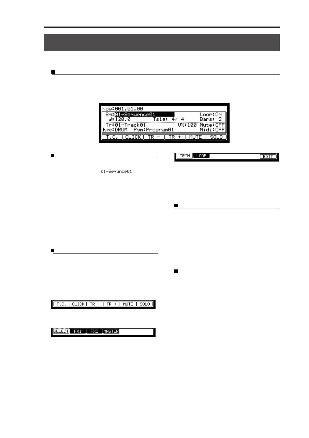
This is the main screen of the MPC2500, where you record and play back sequences. You can go back to this page at any
time by pressing the [MAIN] key; for example, when you get lost while operating MPC2500 and want to go back to this
page. You cannot go back to MAIN page by pressing [MAIN] key while processing (e.g. recording, loading/saving etc..).
Cursor, Cursor Keys, Field, DATA Wheel
The highlighted part on the screen is called the “Cur-
sor” (On above screen, [
] on Main
screen is highlighted).You can move the cursor on the
screen using four cursor keys on the panel. Usually
they move to a specific locations such as right to colon
( : ) . Those locations are called “field”, where you can
make various setting, or enter values. To change the
settings of a field, select the field and turn the [DATA]
wheel on the panel.
This operation, selecting a field by using a cursor key
and changing its settings with the [DATA] wheel, is
the most basic operation of MPC2500.
Function Keys
Six keys (F1 to F6) aligned under the LCD (liquid crys-
tal display) are function keys. Those keys correspond
to each of the six functions that are displayed on the
bottom of the LCD. Pressing each key activates its cor-
responding function. The function that each function
key represents depends on the contents on the LCD.
When the LCD displays like this, pressing function keys
starts some processing or displays windows.
When LCD displays like this, you can switch pages
using function keys F1 to F4. The currently selected
page is displayed with black letters on a white back-
ground. Pressing F5 and F6 keys does not make any
changes.
Some pages display the page selection and processing
function at the same time (see below).
In this case, use F1 and F2 for switching pages, and F6
for activating processing. You cannot use F3, F4 and F5.
In this book, function keys are described something
like this: “[F1] (TRIM) key”- in the bracket, it shows
the function displayed on LCD.
WINDOW key
The MPC2500 has so many functions that they cannot
be displayed in one screen. For efficiency, each page
only displays the most frequently used functions. If
you want to make an advanced setting, press the [WIN-
DOW] key. This opens a window for the detailed set-
ting of the selected field. This is not available for all
fields. When you select a field in which you can use
the [WINDOW] key, the LED of the key is lit.
MODE key
With the MPC2500, each function (such as recording
samples, editing samples, assigning samples to each
pad, editing sequence data, loading from memory
cards, etc…) has a separate screen. These screens are
called “modes”. For example, you will use the
RECORD mode to record samples, and the TRIM mode
to edit samples, the [MODE] key switches modes. By
pressing the [MODE] key and hitting a pad, you can
switch modes. The mode that a pad corresponds to is
displayed above each pad.
MPC2500 Operators Manual rev 1.0
10
Chapter 2: Basic Operation
Setting names
The MPC2500 handles various types of data, from
sound related data (such as samples and programs) to
performance related data (such as sequences and
tracks). These data are managed by names. In this sec-
tion, you will learn how to name different data.
Select a field which you wish to name with the cursor
and turn the DATA wheel. The Name windows will
show up. In the Name windows, you can name the data.
In this window, the cursor is displayed as an underscore instead
of highlights.
You can enter the name, either by using pad or by us-
ing DATA wheel.
Entering letters with DATA wheel
You can change letters selected with a cursor by turn-
ing DATA wheel in the Name window. Move the cur-
sor with RIGHT/LEFT cursor key and enter letters. You
can enter letters using both DATA wheel and pads.
Entering letters with a pad
Two letters are assigned to each pad. By hitting a pad,
the corresponding letter is entered. Below, we will de-
scribe how to enter “Bass 01” instead of “Sequence 01”.
01. Press the UP cursor key to make the first letter capi-
talized.
Pressing the UP cursor key allows you to enter a
capitalized letter.
02. Hit Pad 1 twice.
Hitting Pad 1 once enters A, twice enters B. Each
time you hit the pad, the letter switches between A
and B.
03. Press the RIGHT cursor key and move the cursor to
the right.
If you enter the next letter using a different pad,
the cursor will move to the right automatically.
However, when you enter the letters which are as-
signed to the same pad, you need to press the
RIGHT cursor key to move the cursor manually. In
this example, A and B are assigned to the same pad.
So, you need to move the cursor manually.
04. The next letter is a lower-case letter (“ a ”), so press
the DOWN cursor key.
Pressing the DOWN cursor key allows you to en-
ter lower case letters.
05. Hit Pad 1 once.
The lower case letter “a” is entered.
06. Hit Pad 10 once.
The cursor will move to the right automatically and
a lower-case letter “s” is entered.
07. Press the RIGHT cursor key to move the cursor to
the right and hit the pad 10 once.
08. Press the RIGHT cursor key to move the cursor to
the right and press RIGHT cursor key holding the
[SHIFT] key.
The [SHIFT] + RIGHT cursor key inserts space.
09.
Press the right cursor key to move the cursor one step
to the right, and press the “0” key of Numeric keys.
To enter numeric values, use the numeric keys.
10. Press the “1“ key.
11. Press the RIGHT cursor key to move the cursor to
the right, and press the LEFT cursor key four times
holding the [SHIFT] key.
The [SHIFT] + LEFT cursor keys delete selected letters.
Now “Bass 01” is entered instead of “Sequence 01”.
12. Press [F5] (ENTER) to confirm the entry and close
the window.
Pressing [F4] (CANCEL) cancels the entry and
closes the window. In this case, the name does not
change.
  • Page 1 1
  • Page 2 2
  • Page 3 3
  • Page 4 4
  • Page 5 5
  • Page 6 6
  • Page 7 7
  • Page 8 8
  • Page 9 9
  • Page 10 10
  • Page 11 11
  • Page 12 12
  • Page 13 13
  • Page 14 14
  • Page 15 15
  • Page 16 16
  • Page 17 17
  • Page 18 18
  • Page 19 19
  • Page 20 20
  • Page 21 21
  • Page 22 22
  • Page 23 23
  • Page 24 24
  • Page 25 25
  • Page 26 26
  • Page 27 27
  • Page 28 28
  • Page 29 29
  • Page 30 30
  • Page 31 31
  • Page 32 32
  • Page 33 33
  • Page 34 34
  • Page 35 35
  • Page 36 36
  • Page 37 37
  • Page 38 38
  • Page 39 39
  • Page 40 40
  • Page 41 41
  • Page 42 42
  • Page 43 43
  • Page 44 44
  • Page 45 45
  • Page 46 46
  • Page 47 47
  • Page 48 48
  • Page 49 49
  • Page 50 50
  • Page 51 51
  • Page 52 52
  • Page 53 53
  • Page 54 54
  • Page 55 55
  • Page 56 56
  • Page 57 57
  • Page 58 58
  • Page 59 59
  • Page 60 60
  • Page 61 61
  • Page 62 62
  • Page 63 63
  • Page 64 64
  • Page 65 65
  • Page 66 66
  • Page 67 67
  • Page 68 68
  • Page 69 69
  • Page 70 70
  • Page 71 71
  • Page 72 72
  • Page 73 73
  • Page 74 74
  • Page 75 75
  • Page 76 76
  • Page 77 77
  • Page 78 78
  • Page 79 79
  • Page 80 80
  • Page 81 81
  • Page 82 82
  • Page 83 83
  • Page 84 84
  • Page 85 85
  • Page 86 86
  • Page 87 87
  • Page 88 88
  • Page 89 89
  • Page 90 90
  • Page 91 91
  • Page 92 92
  • Page 93 93
  • Page 94 94
  • Page 95 95
  • Page 96 96
  • Page 97 97
  • Page 98 98
  • Page 99 99
  • Page 100 100
  • Page 101 101
  • Page 102 102
  • Page 103 103
  • Page 104 104
  • Page 105 105
  • Page 106 106
  • Page 107 107
  • Page 108 108
  • Page 109 109
  • Page 110 110
  • Page 111 111
  • Page 112 112
  • Page 113 113
  • Page 114 114
  • Page 115 115
  • Page 116 116
  • Page 117 117
  • Page 118 118
  • Page 119 119
  • Page 120 120
  • Page 121 121
  • Page 122 122
  • Page 123 123
  • Page 124 124
  • Page 125 125
  • Page 126 126
  • Page 127 127
  • Page 128 128
  • Page 129 129
  • Page 130 130
  • Page 131 131
  • Page 132 132
  • Page 133 133
  • Page 134 134
  • Page 135 135
  • Page 136 136

Akai MPC2500 Owner's manual

Category
Recording Equipment
Type
Owner's manual
This manual is also suitable for

Ask a question and I''ll find the answer in the document

Finding information in a document is now easier with AI