Whirlpool 3347017 User manual
- Category
- Washing machines
- Type
- User manual

i
I
I
Part No. 3347017 Rev.
A
I
--
WASHER
1-93
,llt.ln Ovens and Surlace Units. Ranpes, Microwave Ovens. Compaclors. Room Au Condllmners. Dehumldlhers. Aulomatlc Washers. Clolhers Dryers. Freezers. Relr~geralor.Freezers. Ice Makers. Dlshusshen. Bu~ll-In Ovens and Suriace Umls. Rsnpes. Microwave Ovens. Compaclorr, Room Air Condilioners. Dehumidiliers. I

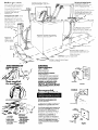
Hot and cold water faucets:
Before you start...
Check location where washer will
,I I^
I,,,
De ~nstallea Proper lnstallatlon Is
your responsibility Make sure you
have everything necessary for
correct installation
Grounded electrical outlet
IS required. See Electrical
requirements.
Standpipe drain system: needs
a two-inch minimum diameter
standpipe with minimum carry-
Untape and open washer IId
Remove packages, hoses, and
1
must be withln 4 feet (122
literature rack from washer
P
A 1 centimeters) of the back of the
washer and provide water
pressure 5-100 PSI (34.5-689.6 KPa).
Laundry tub drain system:
needs a 20.gallon (75 liter) laundry
I
4!!3
II
tub. Top of tub must be at least
34 inches (86 centimeters) high
*
and no higher than 52 inches
(132 centimeters] from bottom of
washer.
/
Tools needed for
InstaIIatfon. .I
Parts supplied
for installation.
away capacity of 17 gallons (64
liters) per minute. Top of star IdpIpe
must be at least 34
Inches (86 centimeters
high and no higher
than 52 inches
If a longer drain hose IS needed,
Part No. 388423 and the hose
extension kit, Part No. 285442, are
authorized parts dist
Water heater: set to deliver 140’ F
) water to the washer
Protection from weather: do not
store or operate washer below 32 F
(O’C). See Use and Care Q/de for
further information
Level floor: maximum slope under
- washer1 inch (25 millimeters).
Remove parts from packages. Check
that all Dads were included.
literature
package
4 drain hose
4 plastic strap
4 flat water
lter
hose washers J~C: washers
4 literature rack
xature rack
(not supplied
lied
with all models1 ielsl
4 hose clamp
e 2 front leveling
1 grounding clamp
legs with nuts
and screw
4 wire form
Electrical
requirements
Prefix “3” Models.
240 Volts, 5.0 Amps.
50 Hz., 8 Amp. fuse.
Electrical ground is required
on this appliance.
A fused electrical supply is required.
[Time-delay fuse or circuit breaker is
recommended.) It is recommended
that a separate circuit serving only
this appliance be provided.
WARNING: AN EXTENSION CORD
SHOULD NOT BE USED WITH THIS
APPLIANCE. SUCH USE MAY RESULT IN
A FIRE, ELECTRICAL SHOCK, OR OTHER
PERSONAL INJURY.
Recommended
grounding method
Do Not, under any circumstances,
remove the power supply cord
grounding prong.
For your personal safety, this appliance
must be grounded. This appliance is
equipped with a power supply cord
having a grounding plug.
To minimize possible shock hazard, the
cord must be plugged into a mating
grounding type wall receptacle,
grounded in accordance with local
codes and ordinances. If a mating wall
receptacle is not available, it is
the personal responsibility and
obligation of the customer to have a
properly grounded wall receptacle
installed by a qualified electrician. See
Figures l-3 to determine the proper
mating wall receptacle for the power
supply cord plug equipped with this
washer.
L...mJ-
240 Volt
grounding type
wau receptacle
Figure 4
Schuko
grounding type
Pow~o;;PPIY
I’ll
Figure 2
ALTERNATE SlYLE
grounding type
wall recsplacle
grounding plug
II
Figure 3
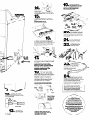
PANEL A

--
-
auuw awn...
With Washer in Laundry Area.
1
Remove tape that covers
H shipping strap. Pull to completely
remove the shipping strap from the
inside of the washer. Read, then
remove label that covers power cord
and drain connector. Peel the tape
down and off each side of cabinet.
Pull firmly to remove the other end of
the shipping strap from the back of the
washer. The shipping strap plug must
be completely removed from the
washer for the self-leveling legs to be
released.
Use new hoses and washers that
came with your Whirlpool washer.
washer
inseti-a flele intoeuchend -
of the inlet hoses. Check that washers
are firmly seated in couplings.
Inlets are
plastic.
,
*
4
Attach hose to bottom inlet
avalve opening first; then
second hose to top inlet. Tighten
couplings by hand. Then use pliers to
make an additional two-thirds turn.
5.
If your washer
has a literature fl
rack, insert the
,/,/-JQ
tabs on sides ’ ,,- -= -ir
in back bane1 of washer, f&.J
and bottom of “
literature rack into holes
Gently push in and down /
7
?
I
until all tabs lock.
Place hose clamp
over washer drain
connector. Push
coupling end of
drain hose onto
washer connector. Use pliers to open
clamp and slide clamp over drain
hose. Check for good fit.
Numbers
correspond
to steps.
7
Slide nozzle end
a
of drain hose
through the
small “loop”
in the wire form. Wrap the
hook end of the wire form
around the drain hose to
form
a
“hook shape:’
8
Move washer close to final
n
position. Put “hook” end
of drain hose into laundry tub or
standpipe. Check for proper length
.
ot drain hose.
If drain hose is too long -
n
disconnect. Remove clamp
and coupling. Estimate length of drain
hose needed. Cut flexible end of hose.
(Do not cut hook-shaped end of drain
hose.)
Push and twist coupling securely
onto drain hose. [You should feel top
of hose through coupling.] Slide clamp
over coupling and hose. Reinstall
drain hose. See step 6.
DO NOT FORCE EXCESS LENGTH
OF DRAIN HOSE DOWN THE
STANDPIPE. THIS COULD CAUSE
SIPHONING.
‘, -j: \ 5,‘~ /
! --
1’ 1
ii
10
Before
attaching
n
water inlet hoses,
run water through both faucets to get
rid of particles in water lines.
11.
Attach bottom hose (inlet marked “H”)
to hot water faucet. ‘Attach top hose
[inlet marked “C”) to cold water faucet.
Tighten coupling to faucet by hand,
then use pliers to make final two-thirds
turn.
PANEL B

19
CHECK ELECTRICAL
n
REQUIREMENTS. BE SURE
Y&l HAVE CORRECT ELECTRICAL
SUPPLY AND RECOMMENDED
GROUNDING METHOD.
into correct
holes at each
front corner of washer until nuts touch
washer.
Do not
tighten nuts until step 17.
15.
Tilt washer backward and remove
corner post(s). Gently lower washer to
floor.
Move washer to its
permanent location.
. .
_-
4
20
Check that all parts are
n
now installed. See parts
list, Panel A. If there is an extra part, go
back through steps to see which step
was skipped.
21
Turn on water faucets
W and check for leaks.
Tighten couplings if there is leaking.
Tilt washer forward raising back legs
1” (25mm) off of floor to adjust rear
self-leveling legs. Gently lower washer to
floor, Check levelness at the washer front
and from front to back on each side
using a carpenter’s level.
22
Untape electrical
cord and plug into
n
grounded outlet.
If washer is not level, screw the front legs
up
or down to adjust. Make final check
with level.
When washer is level, use
wrench to turn nuts on front
legs up tightly against washer
base. If nuts are not tight
against washer base, the
washer may vibrate.
you started with and that the
18
Put “hook” end of drain
H hose in tub or standpipe.
Secure drain hose by wrapping‘the
plastic strap around the hose as shown
in Figures A-C. If drain hose cannot be
strapped in place, it must be cut
exactly to length so the “hook” end is
held tightly over the edge of tub or
standpipe as shown in Figure D.
24
Take a few minutes and
H read the Use and Care
Guide to fully understand your new
washer. Now start the washer and allow
it to complete the regular cycle.
Put the literature in the Literature Rack.
(Literature Rack not supplied with
all models.]
Note: If washer is moved to adjust drain
hose. the washer must be leveled again.
Repeat steps 1547.
Use caution when moving this
appliance to prevent damage to
floor coverings. Before moving,
slide washer onto cardboard
or hardboard to prevent damage.
12
Carefully tilt washer
n
backward until front of
washer is 3-4 inches off of floor. Insert
1 or 2 corner posts.
Hose must be cut
exactty to length
so%ook”endls
hetd tl@tlv over
edge of tub or
standptpe.
You have
successfully installed
your new Whirlpool washer.
To get the most efficient use
I
from your washer, read your
Whirlpool Use and Care Guide.
\
I
Congratulations!
i
actual size
13
Use legs and
n
nuts from parts
CHECK THAT HOSE IS NOT
TWISTED OR KINKED AND IS
package. Screw nut down to within
1/2” of base.
SECURELY IN PLACE.
PANEL C

.6
r’
1
N
Part No. 3347017 Rev. A
Prepared by Whirlpool Corporation, Benton Harbor, Michigan 49022
Printed in U.S.A.
-
 1
1
-
 2
2
-
 3
3
-
 4
4
-
 5
5


Whirlpool 3347017 User manual
- Category
- Washing machines
- Type
- User manual
Ask a question and I''ll find the answer in the document
Finding information in a document is now easier with AI
Related papers
-
Whirlpool 60-Hz Models User manual
-
-
-
-
-
Whirlpool LSR6332KQ0 Installation guide
-
-
-
-
Other documents
-
Inglis IM45001 Installation guide
-
KitchenAid Washer User manual
-
Maytag 120-volt 60-Hz Installation Instructions Manual
-
-
Amana NTW5400T Technical Education
-
Kenmore 11092976101 Owner's manual
-
-
KitchenAid Dishwasher User manual
-
Kenmore Elite 11024892300 User manual
-