Page is loading ...

Tankless Gas Water Heaters
Second Generation
Indoor, Outdoor and Direct Vent
Up to 199,000 BTU
Includes RTG2-42, RTG53, RTG66 and RTG74 models
http://waterheatertimer.org/Troubleshoot-Rheem-Tankless-water-heater.html

SVC 810 Tankless Troubleshooting Manual
1
Table of Contents
Specifications common to all product lines ................................................................................ 4
Product (Model) History .............................................................................................................. 5
Sequence of Operations ................................................................................................................ 7
Sensors and Safety ........................................................................................................................ 8
Oxygen Depletion Sensing System Operation............................................................................ 8
How to Reset the Four (4) Hour ODS Timer.............................................................................. 9
Overheat Film Wrap ................................................................................................................... 9
Heat Exchanger Thermistor ...................................................................................................... 10
Maintenance Panel Display........................................................................................................ 10
Clearing the Fault History ......................................................................................................... 11
Adjusting the Burner Control Assembly (Printed Circuit Board)......................................... 11
How to Check Manifold Gas Pressure...................................................................................... 12
Program Chip Adjustment.........................................................................................................13
Changing the Maximum Temperature Setting to 140° ........................................................... 14
Changing the Maximum Temperature Setting to 120° ........................................................... 14
Error Codes ................................................................................................................................. 15
Diagnostic Points on Printed Circuit Board............................................................................. 18
Thermistor Resistance Chart.....................................................................................................19
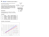
Fan Speed Chart ......................................................................................................................... 20
RTG2-42....................................................................................................................................... 21
Wiring Diagram ........................................................................................................................ 21
Printed Circuit Board ................................................................................................................ 22
RTG 53......................................................................................................................................... 23
Wiring Diagram – RTG 53 ....................................................................................................... 23
Printed Circuit Board – RTG 53 ............................................................................................... 24
RTG 66......................................................................................................................................... 25
Wiring Diagram ........................................................................................................................ 25
Printed Circuit Board ................................................................................................................ 26
Error Code 11 (RTG66 Only)................................................................................................... 26
Error Code 11 (RTG66 Only)................................................................................................... 27
Error Code 51 (RTG 66 Only).................................................................................................. 30
Error Code 61 (RTG 66 Only).................................................................................................. 31
Error Code 65 (RTG66 Only)................................................................................................... 32
Error Code 66 (RTG66 Only)................................................................................................... 33
RTG 74......................................................................................................................................... 34
Wiring Diagram – RTG 74 ....................................................................................................... 34
Printed Circuit Board – RTG 74 ............................................................................................... 35
MIC-180 & EZ Link ................................................................................................................... 36
MIC-180 Printed Circuit Board ................................................................................................ 36
Error Code 03 (MIC-180 & EZLink Only)............................................................................... 37
Test Run Mode.......................................................................................................................... 37
MIC 180 Maintenance Mode Table.......................................................................................... 38
Maintenance Information Mode ............................................................................................... 38
2nd Generation Flame Rod Chart............................................................................................. 39

SVC 810 Tankless Troubleshooting Manual
2
Troubleshooting .......................................................................................................................... 40
Troubleshooting Format and Example...................................................................................... 40
Unit Will Not Power On ........................................................................................................... 41
Error Code 00............................................................................................................................ 44
Warning Code 05 ...................................................................................................................... 44
Warning Code 10 ...................................................................................................................... 45
Error Code 11............................................................................................................................ 45
Error Code 12............................................................................................................................ 49
Error Code 13............................................................................................................................ 50
Error Code 14............................................................................................................................ 51
Error Code 15............................................................................................................................ 52
Error Code 16............................................................................................................................ 53
Error Code 21 (Indoor Models Only) ....................................................................................... 53
Error Code 24............................................................................................................................ 54
Error Code 29............................................................................................................................ 54
Error Code 31............................................................................................................................ 54
Error Code 31............................................................................................................................ 55
Error Code 32............................................................................................................................ 55
Error Code 33............................................................................................................................ 56
Error Code 34............................................................................................................................ 56
Error Code 35............................................................................................................................ 57
Error Code 38............................................................................................................................ 57
Error Code 51............................................................................................................................ 57
Error Code 52............................................................................................................................ 58
Error Code 61............................................................................................................................ 59
Error Code 65............................................................................................................................ 59
Error Code 66 (RTG66 Only)................................................................................................... 60
Error Code 71............................................................................................................................ 60
Error Code 72............................................................................................................................ 60
Error Code 76............................................................................................................................ 61
Error Code 79............................................................................................................................ 61
Error Code 80/81....................................................................................................................... 61
Error Code 82............................................................................................................................ 61
Error Code 90............................................................................................................................ 62
Error Code 99............................................................................................................................ 63
Warning Code IL ...................................................................................................................... 63
Warning Code P1...................................................................................................................... 64
Disassembly and Repair – 1
st
Generation 7.4 product series.................................................. 64
Printed Circuit Board (PCB)..................................................................................................... 64
Air Filter Switch ....................................................................................................................... 65
Water Inlet Solenoid ................................................................................................................. 65
Hot Water Outlet....................................................................................................................... 66
Transformer............................................................................................................................... 66
Fan Assembly............................................................................................................................ 67
Proportional Gas Flow Regulator ............................................................................................. 68
Burner Plate Cover.................................................................................................................... 69

SVC 810 Tankless Troubleshooting Manual
3
Burner Assembly ...................................................................................................................... 69
Igniter and Igniter Probes.......................................................................................................... 70
Flame Rod(s)............................................................................................................................. 70
Heat Exchanger Thermistor ...................................................................................................... 70
Parts ............................................................................................................................................. 71
Parts Exploded View for RTG2-42PV and RTG 53PV............................................................ 74
Parts Exploded View for RTG 53X.......................................................................................... 75
Parts Exploded View for RTG 53DV ....................................................................................... 76
Parts Exploded View for RTG 66DV ....................................................................................... 77
Parts Exploded View for RTG 74PV and GT 199PV............................................................... 78
Parts Exploded View for RTG 74DV and GT 199DV ............................................................. 79
Parts Exploded View for RTG 74X and GT 199X................................................................... 80
Before inspecting, diagnosing, repairing or
operating any water heater, be sure to examine all of
the safety and warning labels on the tank. Follow
the instruction on these warning labels. Read and
understand the Use and Care Manual that was
shipped with the water heater. Failure to do so can
result in unsafe operation of the water heater
resulting in property damage, bodily injury, or
death. Should you have any problems reading or following the instructions in the Use and Care
Manual, seek the help of a licensed and qualified professional.
Copyright 2008, Rheem Manufacturing Company, Water Heater Division.

SVC 810 Tankless Troubleshooting Manual
4
Specifications common to all product lines
Model
See specification sheets for current models and specs
Purpose Domestic Hot Water (DHW) supply for showers, cleaning and laundry
Rated Gas Input (Btu/Hr.)
Modulating
See specification sheets for current models and specs
Dimensions See specification sheets for current models and specs
Installation
Indoor Wall Mounting - can be vented either horizontally or vertically.
Outdoor Wall Mounting - no installed venting required.
Direct Vent – uses special concentric venting for indoor installation.
Working Water Pressure 14 psi minimum; 150 psi maximum
Minimum Water Flow 0.66 gallons per minute to turn on burner
Maximum Flow Rate Based on a 45 degree rise; See specification sheets for current models and specs
Gas Connection 3/4" NPT Male
Water Connection 3/4" NPT Male
Vent Size
3 or 4" Stainless Steel Venting (Category III); 3/5 or 4/7 Direct Vent Stainless
Steel Venting (Category III)
Max. Vent Length See use and care manual for each product type
Inlet Gas Pressure
Natural Gas: Min. 4.0" w.c. Max. 10.5" w.c.
L.P. Gas: Min. 8.0" w.c. Max. 14.0" w.c.
Factory Setting 100°F (With Supplied UMC-117)
Main Control 100°F - 120°F (140°F)
Adjusting Range (All second
generation products will go to
140°F out of the box with DIP
switch adjustment.)
Bath control 100°F - 120°F
Hot Water Supply
Max. Setting – Commercial Heavy
Duty only
Up to 180°F with dip switch adjustment
and UMC Main Remote Control
Electrical Rating 120 VAC/60Hz, 3 Amps
Wire 3 (three) Pin Power Supply Cord
Electrical
Fuse
3A Fuse x 2 (line voltage); 5A fuse on
circuit board
Oxygen Depletion Safety Device (Indoor units only)
Over Heat Limiter for Heat Exchanger
Safety Devices
Heat Exchanger Thermistor (Boiling Point Safety)
Freeze Protection Minus 30°F (Without Wind-Chill Factor) with power applied
Remote Control
Main Remote Control (UMC-117) Standard
Bath Remote control (USC1-117) optional
Second Bath Remote (USC2-117) optional
For the must current specification sheets and use and care manuals, see the
website at www.rheemtankless.com.

SVC 810 Tankless Troubleshooting Manual
5
Product (Model) History
Implementation
Date
Models
Affected
Modification/Upgrade New Parts Board
Programming
September 2004 RTG42 Initial Tankless Product
Launch
n/a n/a
May 2005 RTG74 Initial Product Launch n/a n/a
Dec 2006 RTG74 Gas Valve change; also
included new fuel supply
tubes from gas valve to
burner assembly
RTG74 Water pipes changed.
Removed the two speed
clips from the cold in and
water by-pass.
Second Generation
August 2006 RTG2 42 Upgraded product launch on
new chassis
n/a n/a
No air filter switch n/a n/a
RTG 53
series
Initial Product Launch n/a n/a
No air filter switch n/a n/a
‘dash one’
RTG74
Added EZ link function to
all similar models
EZ link Cable Yes
Added UMC Main remote
control as standard to all
models; allowed residential
units to heat to 140
0
F
UMC 117
Main
Yes
Removed 60 minute lockout
timer for return circulation
function
No Yes
Power Restore Auto On
feature added. Unit resets to
last recorded temperature
setting
No Yes
Water flow inlet valve
solenoid will close
completely when using EZ
link cable or MIC 180
No Yes
Allowed all 2
nd
generation
units to be installed with
MIC 180
No Yes
Sep29 + Oct
2006
New ‘dash
one’ RTG
74
RTG 74 chassis only Yes Yes

SVC 810 Tankless Troubleshooting Manual
6
Implementation
Date
Models
Affected
Modification/Upgrade New Parts Board
Programming
Flame rod and igniter on
right hand burner swapped;
added a ‘target’ for the
spark to hit
Burner No
Improved burner cover plate Burner cover
plate
No
New programming chip –
all RTG74 models. The new
burner plate cover modified
the air flow characteristics.
This means the chip
programming had to
change.
Programming
Chips; this is
when the 2
chips in a bag
started.
Yes
December 5,
2006
‘dash two’
model
RTG 74 chassis only Yes Yes
Removed transformer. 120v
AC is the primary power
source to board
No Yes
Manifold pressure changed No Yes
Programming chip changed
to reflect new manifold
pressures
Programming
Chips
Yes
Moved gas inlet connection
to outside the chassis for
easier replacement
No No
RTG 53/2-42 chassis
New igniter | New wire
harness for igniter | New
location
Yes Yes
July 1, 2008 RTG 66 Direct Vent model only;
altitude configured via dip
switch settings; inlet gas
pressure check port added
Many Yes

SVC 810 Tankless Troubleshooting Manual
7
Sequence of Operations
Action Explanation
Hot water faucet is open creating a demand Hot water draw initiates water flow thru
the machine.
Water flows through the Water Flow Sensor Minimum flow rate of .66 gallons per
minute.
Printed Circuit Board (PCB) senses the flow
rate has reached a minimum demand of 0.66
gpm
PCB is the ‘brains’ of the machine and
controls all input and actions during
sequence of operations.
Fan conducts a pre-purge Pre purge is designed to verify we have a
clear and clean vent.
The Proportional Gas Flow Regulator allows
the gas to flow to the main burner
PGFR opens to full BTU input initially.
At the same time, the igniter continuously
sparks and ignites the main burner
The spark igniter ignites the fuel in the
main burner area. Both left and right
burner will fire initially.
After ignition, the Flame Rods sense and
monitor the flame and ensures combustion
The purpose of the flame rods is to verify
flame. In the event of flame failure (or
presence when none is expect) the unit will
go into an error code.
The “In Use Indicator” on remote control
turns "ON" (Red) and the Priority Indicator
turns Green (multiple remote controls).
Main Burner is now lit. The PCB goes thru
a series of calculations (input sensing) to
balance out the cold-water temperature, the
thermostat setting, the hot outlet
temperature and the BTU required to heat
the water.
The Proportional Gas Flow Regulator Valve
continuously adjusts the gas volume in order to
maintain the outlet temperature. The water
flow sensor also adjusts the proper amount of
cold water mix flow to supply a stable hot
water temperature at all times. A signal is also
sent to the fan motor in order to constantly
maintain the correct proportion between the
gas volume and air volume.
Again, the PCB is constantly monitoring
all of these inputs and actions to ensure the
outlet water temperature is within 1 degree
of thermostat setting. It also monitors the
BTU required to heat the cold water to the
thermostat setting and adjusts the gas valve
accordingly.

SVC 810 Tankless Troubleshooting Manual
8
Action Explanation
(For indoor model only) When the air intake is
blocked, or oxygen in a room is not sufficient,
the output of the thermocouple that is located
in the Oxygen Depletion Sensing Burner
(ODS) will change.
The PC Board senses this change and
controls the Fan and Proportional Gas
Control Valve in order to prevent imperfect
combustion. If the control board cannot
correct such condition, the unit will go into
an error code.
When the hot water tap is closed, the flow rate
signal from water flow sensor stops.
Gas valve is closed. Main burner shuts off.
The fan conducts a post purge. The purpose of the post purge is to cool the
heat exchanger.
Sensors and Safety
Oxygen Depletion Sensing System Operation
Oxygen Depletion Safety Device (ODSD) Sensing
Burner - Indoor Model Only
The sensing burner is a primary air type ceramic
burner that consists of an outer jacket surrounding
the flame opening and a thermocouple to detect
flame temperature. The sensing burner is located in
the part of the main burner and designed to monitor the flame condition at all times. In case the
oxygen level decreases due to blocked or clogged air intake or flue venting or by contaminated
air (not enough oxygen content), location of the flame, as well as its temperature, will change.
This change will be detected by the ODSD thermocouple.
The unit will attempt to resolve the problem on its own by adjusting the
quantity of fuel and adjusting the fan speed. During this resolution period,
the unit will show a flash code of 05 and have an audible alarm. In the
event the unit cannot fix the fuel air mixture, the unit will shut down with
a flash code of 13.
Here is how the ODS sensing system works.
1 Is the ODS thermocouple detecting normal
temperatures?
Yes Unit is operating normally. ODS Thermocouple
will detect proper temperature with 2 minutes on
a cold start and within 1 minute on a warm start.
No
2 Printed Circuit Board (PCB) will increase the
airflow rate to balance the air-fuel mixture.
PCB automatically tries to fix the problem with
increased airflow.
3 Is the ODS thermocouple detecting normal
temperatures?
Yes Unit is operating normally.

SVC 810 Tankless Troubleshooting Manual
9
No
4 Second attempt by the PCB to increase the
airflow rate to balance the air-fuel mixture.
PCB continues to try to fix the air-fuel mixture
my adding airflow. It now adds a visual alarm on
the Remote Control by flashing both the red and
green indicators.
5 Is the ODS thermocouple detecting normal
temperatures?
Yes Unit is operating normally.
No
6 Third attempt by the PCB to increase the airflow
rate to balance the air-fuel mixture.
PCB continues to try to fix the air-fuel mixture
by adding airflow. It now adds an audible alarm
on the Remote Control by sounding a tone every
60 seconds and flashes a monitor code of 05.
7 Is the ODS thermocouple detecting normal
temperatures?
Yes Unit is operating normally.
No
8 Final attempt by the PCB to increase the airflow
rate to balance the air-fuel mixture.
If the unit does not detect normal ODS
thermocouple temperatures, then unit will shut
down with an error code of 13.
NOTE
Shutdown by imperfect combustion can be reset by pressing power switch (ON/OFF Button). If
shutdown occurs 5 times within 4 hours, the water heater will not recover for the next 4 hours.
How to Reset the Four (4) Hour ODS Timer
1. Turn the unit OFF. Remove the front cover. Locate the dip switches on the control board.
2. Make sure all the dip switches are OFF (down position).
3. Locate the #2 dip switch and turn it ON (up position) then immediately turn it off.
4. Within 5 seconds, press and hold both the MIN and MAX button for at least 2 seconds.
5. The remote control will flash briefly. This is your signal that the fault history has been cleared.
6. You can operate the machine.
Overheat Film Wrap
The Overheat Film Wrap detects the heat
exchanger if and when it overheats. The over
heat limiter is the plastic film wrap with the
black squiggly lines.
It constantly monitors the heat exchanger
temperature and will show an Error Code 14
in the event the heat exchanger gets too hot.

SVC 810 Tankless Troubleshooting Manual
10
Heat Exchanger Thermistor
The Heat Exchanger Thermistor monitors the temperature of the water
inside the heat exchanger. It will activate to Error Code 15 if the water
temperature exceeds 207º F for more than 15 seconds; or 230º F for more
than 1 second. It will also show an Error Code 32 if the thermistor is
disconnected from the circuit board.
Maintenance Panel Display
The Rheem Tankless has a Maintenance Display chart on the remote
control panel. To access the Maintenance Display, turn the unit OFF.
Then hold down the UP and DOWN arrow keys at the same time for a
few seconds. You will hear an audible beep and see the display go to
0E. By pressing the UP and DOWN arrow keys on the remote display,
you can access a variety of information about the machine. For Example
a code at 3E (recent faults) may display as 21 (Error Code 21).
Shortcut: Lift dip switch #1 to the up position to go immediately into maintenance mode.
First Digit – Use DOWN (▼)arrow key on Remote Control
0* 1* 2* 3* 4* 5* 6* 7* 8* 9*
*E Null Fault Codes of the most recent 8 faults Null
*F Null Sequence Number of the most recent 8 faults Null
*C Total combustion times until recent error fault (** x 10000times) Null
*D Total combustion times until recent error fault (** x 100 times) Null
*H Total combustion period until recent error fault (** x 1000 hours) Null
*J Total combustion period until recent error fault (** x 10 hours) Null
*Y
Flame Rod
Status
GPM Flow Rate
(*.* gpm)
Ambient Air
Thermistor
Temperature
Cold Water Inlet
Thermistor
Temperature
Heat Exchanger
Thermistor
Temperature
Hot Water Outlet
Thermistor
Temperature
Fan Speed x 100
RPM
Power for
P.G.F.R. valve
Null
Null
Second Digit – Use UP (►) arrow key on Remote
Control
*A
Thermo
Electromot
ive Force
Control
Line
Volta
g
e
Fan
Detective
Value
Fan Motor
Current
Null
Null
Null
Null
Null
Sequence
Number
You can turn the unit on while in Maintenance Mode by quickly pressing the ON/OFF button
one time. The temperature will default to 120 degrees and will not display because you are still
in Maintenance Mode. If you demand hot water, the unit will fire off and you will be able to read
the “Y” line in real time. That means you will see the actual flow rate in gallons per minute, the
cold-water inlet temperature, the hot water outlet temperature, heat exchanger temperature, and
flame rod status.

SVC 810 Tankless Troubleshooting Manual
11
Clearing the Fault History
1. Turn the unit OFF. Remove the front cover. Locate the
dip switches on the control board.
2. Make sure all the dip switches are OFF (down
position).
3. Locate the #1 dip switch and turn it ON; then turn it
OFF.
4. Within 5 seconds of turning the dip switch off, press
and hold the MIN (SW1) or MAX (SW2) button for at
least 2 seconds.
5. The remote control will flash briefly. This is your
signal that the fault history has been cleared.
6. You can verify clearing of fault history by entering Maintenance Mode and check the
code at location 1E. It should read NULL or ┌┐.
Adjusting the Burner Control Assembly (Printed Circuit Board)
The purpose of this procedure is the balance the fuel pressure and air volume at the burner
manifolds. This procedure will ensure that you get optimal performance of the modulating
characteristics of the unit by allowing firing rates between 19,000 BTU (minimum) and 199,900
BTU (maximum).
WARNING: You will need to perform this procedure when you replace the PCB or install a
new altitude chip. Without the adjustment, the water heater may not function properly.
When replacing the printed circuit boards adjust as follows.
Measurement of Fan Pressure:
Measure the fan pressure before adjusting the burner manifold pressure. The fan pressure differs
depending on models, types of gas and installation condition. Measure the fan pressure at each
installation site.
1. Measurement of "Minimum" Capacity
a. Without opening the hot water tap, push the “SW1"
Button on PC Board.
b. Using the manometer, measure and record the pressure (in. w.c.).
2. Measurement of "Maximum" Capacity
a. Without opening the hot water tap, push the "SW2" Button on PC Board.
b. Using the manometer, measure and record the pressure (in. w.c.).
Adjustment of Burner Manifold Pressure:
NOTE: Always start from "Minimum" when adjusts the burner manifold pressure. The
display is on remote control. Always connect the remote control to monitor this procedure.
1. Adjustment of "Minimum" capacity
a. Open the hot water tap gradually until the water heater ignites at the minimum

SVC 810 Tankless Troubleshooting Manual
12
operating water flow.
b. Push the Adjusting Button on the PC Board. [LH] is displayed on the LED of
remote control.
c. Hold the Adjusting Button; push the "SW1" button on the PC Board. The
current number [01 - 39] is displayed on the LED of remote control.
NOTE: Every time you press the MIN button, the display will cycle up to the number 39. Once
it reaches 39, it will automatically reverse and cycle back down to 1.
d. You can change the gas pressure by pushing the "SW1" button. Using the
manometer, adjust the minimum manifold pressure to the standard pressure plus
the measured minimum fan pressure.
e. Release the "SW1" button.
2. Adjustment of "Maximum" capacity
a. Open the hot water tap fully to allow the water heater to ignite a maximum
operating flow. You may need to turn on up to three fixtures to get max water
flow.
b. Push the Adjusting Button on the PC Board. [LH] is displayed on the LED of
remote control.
c. Hold the Adjusting Button; push the "SW2" Button on the PC Board. The current
figure [01 - 39] is displayed on the LED of remote control.
d. You can change the test gas pressure by pushing the "SW2" button every time.
Using the manometer, adjust the minimum manifold pressure to the standard
pressure plus the measured maximum fan pressure.
e. Release the "SW2" button.
Note: If [EE] is displayed on the LED of remote control, adjust again with caution. This means
there was an error in the adjustment sequence.
How to Check Manifold Gas Pressure
When the “MAX” or “MIN” button is pushed, the combustion is fixed at the respective firing rate.
The LED of remote control displays 1L (minimum combustion) or 3H (maximum combustion).
The adjusted manifold pressure must be as follows.
RTG74-Indoor
MAX. (in. w.c.) MIN. (in. w.c.)
N
AT. Gas 2.52+ fan pressure (max.) 0.45+ fan pressure (min.)
L.P. Gas 7.36+ fan pressure (max.) 1.22+ fan pressure (min.)
RTG74 -Outdoor MAX. (in. w.c.) MIN. (in. w.c.)
N
AT. Gas 2.32+ fan pressure (max.) 0.43+ fan pressure (min.)
L.P. Gas 6.61+ fan pressure (max.) 1.10+ fan pressure(min.)
Second Generation Product Fan Speeds
42PVP 2nd 2.52 + fan pressure (max.) 0.45 + fan pressure (min.)
42PVN 2nd 2.36 + fan pressure (max.) 0.45 + fan pressure (min.)
53PVP 3.50 + fan pressure (max.) 0.45 + fan pressure (min.)
53PVN 3.46 + fan pressure (max.) 0.45 + fan pressure (min.)

SVC 810 Tankless Troubleshooting Manual
13
53XP 3.46 + fan pressure (max.) 0.55 + fan pressure (min.)
53XN 2.83 + fan pressure (max.) 0.49 + fan pressure (min.)
53DVP 3.01 + fan pressure (max.) 0.37 + fan pressure (min.)
53DVN 2.95 + fan pressure (max.) 0.39 + fan pressure (min.)
74DVP 7.28 + fan pressure (max.) 1.15 + fan pressure (min.)
74DVN 2.36 0.42 + fan pressure (min.)
Program Chip Adjustment
To quickly establish someone’s altitude with zip code use the
following link. Type the zip code in the upper left hand corner and
hit enter, it will bring up current weather conditions and include
the altitude.
http://www.wunderground.com/
When the water heater is installed above
3,280 feet, adjustment of the Program Chip is
required. Without adjusting the Program
Chip, the water heater may not function
properly. If the water heater is installed less
than 3,280 feet, no Program chip is required
or supplied and no action is necessary. A
different Program chip is required for every
3,280 feet. The Program chip is not
interchangeable between Indoor and
Outdoor models or types of gas.
1. Check the altitude (above sea level) where the water heater is installed.
2. Ensure that you have the correct Program chip for proper model, gas type and altitude.
3. Disconnect the electric power to the water heater. Turn off the gas shutoff valve and
water shutoff valve.
4. Remove the front cover.
5. Place Program Chip as shown on PCB.
6. Turn on the electric power.
7. Find the DIP Switch #1 and #2 located at the top left hand side of the PCB.
8. Change the DIP Switch #1 and #2 setting to the "ON" position. DO NOT alter any other
DIP Switch.
9. The LED on the PCB is flashing. At the same time, the display of the remote control
starts to flash.
10. Find the Adjusting Button located at the top left hand side of the PCB.
11. Press the Adjusting Button on the PCB. The display of the PCB and the remote control
changes from "Flashing" to "Illuminating".
12. Change the Dip Switch #1 and #2 setting to the "OFF" position. DO NOT alter any other

SVC 810 Tankless Troubleshooting Manual
14
DIP Switch. The LED on the PCB and the display of the remote control stops
illuminating.
13. Attach the unit's front cover.
14. Turn on the gas shutoff valve and water shutoff valve.
15. Check and ensure safe operation and performance of the water heater.
Changing the Maximum Temperature Setting to 140
°
By installing the UMC- Main Remote Control, you can adjust the maximum temperature
setting to 140 degrees F. Water temperature settings of 130°F and 140°F can be achieved only
when using MAIN remote control. The water
temperature is set at 100°F from the factory.
To adjust the unit to create water temperatures
from 130 or 140 degrees, you must perform a
DIP Switch adjust as follows:
1. Turn off remote control. Leave the unit
plugged into a 120 VAC power source.
2. Turn off the gas and water shutoff
valves.
3. Remove the front cover.
4. Find the DIP Switch #4 located at the top
left hand side of the PCB.
5. Change the DIP Switch #4 setting to the
"ON" position. DO NOT alter any other
DIP Switch.
6. The LED on the PCB is flashing. At the same time, the display of the Main Remote
Control starts to flash.
7. Press the "SW2" Button on the left hand side of the PCB for more than 1 second.
8. The LED on the PCB starts illuminating continuously. At the same time, the display of
the Main Remote Control is on continuously.
9. Change the DIP Switch #4 setting back to the "OFF" position. DO NOT alter any other
DIP Switch.
10. The LED on the PCB will stop illuminating. At the same time, the display of the Main
Remote Control will turn off.
11. Attach the unit's front cover.
12. Turn on the remote control, gas and water shutoff valves.
13. Check and ensure safe operation and performance of the water heater.
Changing the Maximum Temperature Setting to 120
°
Follow the instruction below if it is determined that a setting of 130°F or 140°F is no longer
required and you want to return to a maximum water temperature of 120°.

SVC 810 Tankless Troubleshooting Manual
15
1. Turn off remote control. Leave the unit plugged into a 120 VAC power source.
2. Turn off the gas and water shutoff valves.
3. Remove the front cover.
4. Find the DIP Switch #4 located at the top left hand side of the PCB.
5. Change the DIP Switch #4 setting to the "ON" position. DO NOT alter any other DIP
Switch. The LED on the PCB is on. At the same time, the display of the Main Remote
Control is on continuously.
6. Press the "SW1" Button on the left hand side of the PCB for more than 1 second. The
LED on the PCB starts flashing. At the same time, the display of the Main Remote
Control starts to flash.
7. Change the DIP Switch #4 setting back to the "OFF" position. DO NOT alter any other
DIP Switch. The LED on the PCB will stop flashing. At the same time, the display of the
Main Remote Control will turn off.
8. Attach the unit's front cover.
9. Turn on the remote control, gas and water shutoff valves.
10. Check and ensure safe operation and performance of the water heater.
Error Codes
Code Fault Remedy
00
1 Hour continuous combustion
(First generation products only –
mfg date thru Jul 06)
Close all hot water taps to reset unit.
Turn off, or remove circulation pumps (unit is not designed for
continuous operation with circulation systems).
03
MIC 180 and EZ Link Only Check communications cable.
Check #4 dip switch setting to ON position.
05
Imperfect Combustion Alarm Clean air inlet filter.
Clean combustion air fan.
Clean heat exchanger fins.
Check for adequate combustion air ventilation openings and clean if
necessary.
Check vent system for partial blockage and correct as necessary.
10
Warning or Predictive Code –
not a fault code.
Air Supply or Exhaust Blockage
Check all vent components for proper connections.
Check that nothing is blocking the flue inlet or exhaust.
Ensure condensation trap/drain was installed correctly.
Ensure heat exchanger fins, fan, and air intake are not blocked.
11
No Ignition Ensure you have gas to the appliance and valves are turned ON.
Ensure gas type and pressure is correct.
Bleed all air from gas lines.
Ensure gas line, meter, and regulator are sized properly.
Ensure appliance is properly grounded.
Check gas solenoid valves for open or short circuits.
Ensure igniter is operational.
Check igniter wiring harness for damage.
12
Flame Failure (had main burner,
then lost it)
Ensure gas type and pressure is correct.
Bleed all air from gas lines.
Ensure flame rod wire is connected.
Check flame rod for carbon build-up.
Ensure gas line, meter, and regulator are sized properly.

SVC 810 Tankless Troubleshooting Manual
16
Ensure appliance is properly grounded.
Check gas solenoid valves for open or short circuits.
Check power supply for proper voltage and voltage drops.
Disconnect remote control; see if it runs.
Disconnect and re-connect all wiring harnesses on unit and PC board.
13
Oxygen Depletion Sensor (Poor
or Improper Combustion)
Ensure there is plenty of fresh air to the unit.
Unit needs 1 square inch for each 1,000 BTU of input. That is up to 200
square inches or a space 14 ½ x 14 ½ inches.
14
Overheat Wrap Fault Ensure high fire and low fire manifold pressure is correct.
Check gas type of unit and ensure it matches gas type being used.
Check heat exchanger for cracks and/or separations.
Check for improper program chip.
Check for restrictions in airflow around unit and vent terminal.
15
Boiling Safety Device Check for closed water heater inlet valve or restrictions in cold water
inlet pipe (must be fully open).
Check for clogged heat exchanger (scale buildup).
On commercial water heater, lower set point temperature below 180
0
F at
high altitude.
16
Over Temperature Warning Check for clogged heat exchanger.
Check for restrictions in airflow around unit and vent terminal.
21
Malfunction of Air Intake Filter
Switch (Indoor Products Only)
Make sure air filter door is properly seated.
Make sure front panel is properly installed.
24
Malfunction of Operational
Switch
Disconnect remote control and retry.
Verify unit is electrically grounded.
Press max button on PCB to reset; Press min button on PCB to reset.
29
Heat Exchanger Outlet Temp.
Too Low
Clean air inlet screen.
Clean heat exchanger fins
31
Water Inlet Temperature Sensor
Fault
Check sensor wiring for damage.
Ohm out sensor
Check and clean scale from sensor.
32
Heat Exchanger Temperature
Sensor Fault
Check sensor wiring for damage.
Ohm out sensor
Check and clean scale from sensor.
33
Outgoing Water Temperature
Sensor Fault
Check sensor wiring for damage.
Ohm out sensor
Check and clean scale from sensor.
34
Combustion Air Temperature
Sensor Fault
Check sensor wiring for damage; Ohm out sensor
Check and clean ambient air temperature sensor.
Ensure fan blade is tight on motor shaft and it is in good condition.
Check for restrictions in airflow around unit and vent terminal.
35
Improper Thermistor
Connection
Check that all thermistors are connected to proper connections on PCB.
38
ODS Sensor has malfunctioned. The sensor itself is not responding to a self check from the printed circuit
board.
Check wiring harness.
Check for proper voltage to ODS
51
Gas Inlet Solenoid Valve Fault Check gas inlet solenoid valve wiring harness for loose or damaged
terminals.
Ohm out solenoid valve.

SVC 810 Tankless Troubleshooting Manual
17
52
Modulating Solenoid Valve
Fault
Check modulating gas solenoid valve wiring harness for loose or
damaged terminals.
Ohm out solenoid valve.
61
Combustion Fan Failure Ensure fan motor will turn freely. Motor will operate with a small
amount of restriction.
Check wiring harness to motor for damaged and/or loose connections.
Check venting length not to exceed max lengths and bends.
65
Water Volume Control Fault Check water flow solenoid valve wiring harness for loose or damaged
terminals.
Check for proper voltage to water flow solenoid.
66
Water By-Pass Control Fault Check water by-pass solenoid valve wiring harness for loose or damaged
terminals.
Check for proper voltage to water by-pass solenoid
71
Gas Inlet Solenoid Valve
Control Fault
Check gas inlet solenoid valve wiring harness for loose or damaged
terminals.
Ohm out solenoid valve.
72
Flame Sensing Device Fault Ensure flame rod is touching flame when unit fires.
Check inside burner chamber for any foreign material blocking flame at
flame rod.
Check all wiring to flame rod for damage.
Check flame rod for proper voltage.
Remove flame rod and check, clean with steel wool.
76
Communication Fault with
Remote Control
Check remote control wiring for loose or damaged connections.
Bypass remote control cable by connecting remote control directly to
remote control terminals on PCB. Replace cable if found to be faulty.
79
Fan Motor Current Fault Ensure fan motor will turn freely. Motor will operate with a small
amount of restriction.
Check fan motor for proper voltage and for water (condensation) damage
80, 81
Gas Cut-off Failure Ohm out all solenoid valves.
Check voltage of all flame rods.
82
PCB data failure. Control board
is not programmed.
Program PCB for proper altitude and fuel type circuit board with proper
programming chip.
90
Blocked Flue Fault Clean any blockage in heat exchanger, combustion fan, inlet filter, and
exhaust flue.
99
Fan Motor cannot vent Clean Air Inlet Screen; Clear vent blockages
Check for blocked heat exchanger
No
code
Nothing happens when water is
flowing through unit.
Make sure unit is connected to proper power supply and circuit breakers
are on.
Clean inlet water supply filter.
Ensure you have at least the minimum flow rate required to fire unit.
On new installations ensure hot and cold water lines are not crossed.

SVC 810 Tankless Troubleshooting Manual
18
Diagnostic Points on Printed Circuit Board
Measurement Point
Connection Wire Color
Normal Value What you are checking?
I – J AC 90 – 110V Do you have power to the control board?
U W1 – W2 50K Ω – 500K Ω Is the Over Heat Film Wrap OK?
BR1 – BK2 DC 2 - 5V (pulse)
More than 1,310
pulses/minute is
nominal.
Does the water flow sensor send a pulse?
(Only when water is flowing thru control)
S
R3 – BK2 DC 11 – 17 V Does the water flow sensor have voltage?
(Power ON; no water flow)
B4 – W6 DC 120 – 160 V Does the fan motor have the proper voltage?
R3 – B4 DC 12 - 18 V Does the fan motor have proper voltage?
G
Y1 – B4 DC 4 – 10 (Pulse) Is the fan motor producing a regular pulse?
R W6 – BK3 68
0
F = @ 10.3 KΩ Is the cold water inlet thermistor working?
R Y5 – BK3 104
0
F = @ 4.9 KΩ Is the heat exchanger thermistor working?
R R4 – BK3 104
0
F = @ 4.9 KΩ Is the hot water outlet thermistor working?
R B7 – BK3 68
0
F = @ 10.3 KΩ Is the ambient air thermistor working?
R R1 – BK2 DC 1.5 - 14 V
40 – 80Ω
Is the P.G.F.R. valve operating?
(Proportional Gas Flow Regulating Valve)
L R1 – GND AC 1 – 100 V
M W1 – GND AC 1– 100 V
T B1 – GND AC 1 – 100 V
Are the three flame rods detecting flame?
Flame Rod 1 is the white wire and goes to the right front half burner.
Flame Rod 2
is the red wire and goes to the right rear half burner.
Flame Rod 3
is the blue wire and goes to the left burner. (74 series only)
H GY2 – GY5 AC 90 - 110 V Is the igniter working properly
All models except RTG66: These are the two green wires at connector H. They are the two green wires
to the by by-pass solenoid on the water flow valve. When the cold water bypass solenoid is closed, must
be 0 volts DC. (Remote set at 118F ~ 180F). When the cold water bypass opens, voltage reads about 80
volts DC. (Remote is set to 100F~116F).
K Y1- BK5 DC 75 - 100 V
.8 – 2.2. KΩ
Is the solenoid (SV0) working?
(Primary fuel inlet to gas valve)
K W2- BK5 DC 75 - 100 V
.8 – 2.2. KΩ
Is the solenoid valve (SV1) working?
(Fuel to ODS and front right burner)
K R3- BK5 DC 75 - 100 V
.8 – 2.2. KΩ
Is the solenoid valve (SV2) working?
(Fuel to back right burner)
K B4- BK5 DC 75 - 100 V
.8 – 2.2. KΩ
Is the solenoid valve (SV3) working?
(Fuel to left side burner)
W2 – BK8 DC 8 – 16V Does the water volume control motor have
proper voltage?
R7 – BK8 DC 8 – 16V Does the water volume control motor have
proper voltage?
B
GR6 – BK8 Less than 1V DC
(Limiter on)
DC4 – 6 V (Limiter
Off)
Is the water volume control switch OK?

SVC 810 Tankless Troubleshooting Manual
19
Q R1 – W2 DC8 – 30V
(measured 2 minutes
after combustion
startup)
P 1 – 2 DC8 – 30V
(measured 2 minutes
after combustion
startup)
Is the thermo-electromotive force OK?
O W1 – W2 Less than 1V DC;
Less than 1Ω
Is the air intake switch working?
Thermistor Resistance Chart
Temp
°F
Resistance
KΩ
Temp
°F
Resistance
KΩ
Temp
°F
Resistance
KΩ
Temp
°F
Resistance
KΩ
32 23.73 77 8.494 122 3.485 167 1.598
33.8 22.706 78.8 8.177 123.8 3.371 168.8 1.552
35.6 21.733 80.6 7.873 125.6 3.262 170.6 1.508
37.4 20.806 82.4 7.583 127.4 3.156 172.4 1.465
39.2 19.925 84.2 7.304 129.2 3.055 174.2 1.424
41 19.085 86 7.037 131 2.957 176 1.384
42.8 18.286 87.8 6.781 132.8 2.863 177.8 1.345
44.6 17.525 89.6 6.536 134.6 2.773 179.6 1.307
46.4 16.799 91.4 6.302 136.4 2.686 181.4 1.271
48.2 16.108 93.2 6.076 138.2 2.602 183.2 1.236
50 15.449 95 5.86 140 2.52 185 1.202
51.8 14.82 96.8 5.653 141.8 2.442 186.8 1.169
53.6 14.221 98.6 5.454 143.6 2.367 188.6 1.137
55.4 13.469 100.4 5.264 145.4 2.295 190.4 1.106
57.2 13.104 102.2 5.081 147.2 2.225 192.2 1.077
59 12.583 104 4.905 149 2.157 194 1.048
60.8 12.086 105.8 4.736 150.8 2.092 195.8 1.02
62.6 11.611 107.6 4.574 152.6 2.029 197.6 0.993
64.4 11.157 109.4 4.418 154.4 1.968 199.4 0.966
66.2 10.723 111.2 4.269 156.2 1.91 201.2 0.941
68 10.309 113 4.125 158 1.853 203 0.916
69.8 9.913 114.8 3.987 159.8 1.799 204.8 0.893
71.6 9.534 116.6 3.854 161.6 1.746 206.6 0.869
73.4 9.172 118.4 3.726 163.4 1.695 208.4 0.847
75.2 8.826 120.2 3.603 165.2 1.646 210.2 0.825
/