NR501-OD, NR662-OD Series Heat Exchanger Replacement Procedure
Diagram
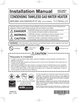
1.
(1) Disconnect electrical power to unit
(2) Turn off gas and water
(3) Remove 4 screws
(4) Remove drain 2 valves and drain the unit completely
(5) Remove the cover - circuit board
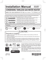
2.
(1) Disconnect the connectors from the circuit board
(2) Remove 2 ground wires
(3) Remove the circuit board; there is a screw on middle-
upper of the circuit board. Let the circuit board hang
outside of the unit
3.
(1) Unplug Flame Rod and Ignition Plug
(2) Loosen the cable tie and unplug the freeze prevention
heater, thermal fuse (2)
(3) Unplug the high limit switch and the thermistor - heat
exchanger
(4) Unplug all wires that attach to the wiring harness
except water servo - main
Page 2
Unplug all wires that attach to the wiring harness and the
body of water heater
Procedure
Remove the front cover
Disconnect the connectors from the circuit board and
remove the ground wire, and the circuit board
(4)
(1)
(2)
Cover - Circuit Board
(3)
Water Servo - Main