La Crosse Technology TX31U-IT User manual
- Category
- Weather stations
- Type
- User manual

1
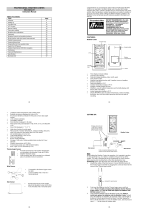
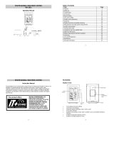
QUICK SET UP MANUAL –
PROFESSIONAL WEATHER CENTER
Using 915MHz wireless transmission of weather data, this unique weather station can
be powered using batteries for all your weather needs in the home or office.
INSTANT TRANSMISSION is the state-of-
the-art new wireless transmission
technology, exclusively designed and
developed by LA CROSSE TECHNOLOGY.
INSTANT TRANSMISSION offers you an
immediate update (every 4.5 seconds!)
(every 6.5 seconds for rain!) of all your
outdoor data measured from the
transmitters: follow your climatic variations
in real-time!
This product offers:
2
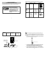
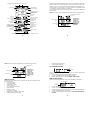
Carefully open and check that the following contents are complete:
Item: Consisting of: Fittings: Illustration:
Base Station
1) Main unit
Thermo-
Hygro
Sensor
(TX31U-IT)
1) Main unit
2) Air Flow
cover
1) Wall mounting
screws
2) Plastic anchors
for screws
3) 2 x cable ties
Wind Sensor
(TX23U)
1) Main unit
with wind
vane
2) 32 ft cable
(already
attached the
main unit)
3) Mast holder
1) 1 x U-bolts for
mast holder
2) 2 x Washers
3) 2 x Nuts
4) 2 x cable ties
3
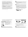
Cable connection between the wind sensor and the thermo-hygro sensor
Wireless transmission
at 915 MHz - thermo-
hygro and rain sensor
to the Weather Center
Weather Center
Wind sensor
Rain senso
r
Rain Sensor
(TX32U-IT)
1) Base and
funnel
1) 2 x Screws
and Plastic
anchors
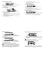
SETTING UP:
4
Sockets for wind sensor
Note:
When putting the Weather Center into operation, it is important to perform in close
proximity (e.g. on a table) a complete wiring and set-up of the system. This step is
important to test all components for correct function before placing and mounting them
at their final destinations (See Positioning below). Spin the wind vane and tip the rain
gauge to test.
1. Unwind the cables of the Wind sensor. Connect the Wind sensor to the Thermo-
hygro transmitter by plugging the connector head into the socket of the Thermo-
hygro sensor. The cord should “click” into place.
2. First insert the batteries into the Thermo-hygro sensor and Rain sensor (“How
to install and replace the batteries into the Thermo-hygro sensor“ and
“How to install and replace the batteries into the Rain sensor” below).
3. Then insert the batteries into the Weather Center (see “How to install and
replace the batteries into the Weather Center” below). Once the batteries are
installed, all segments of the LCD will light up briefly and a short signal tone will

5
be heard. It will then display the time as 12:00, the date as 1.1.05, the weather
icons, and air pressure value. "- - -" will be shown for outdoor data.
4. Afterwards, the Weather Center will start receiving data from the transmitter.
The transmission reception icon will be blinking to indicate that the station is
trying to get the thermo-hygro transmitter data. The outdoor temperature,
humidity, wind data should then be displayed on the Weather Center. If this
does not happen after 135 seconds, the batteries will need to be removed from
all units. You will have to start again from step 2.
5. The transmitter reception icon is now blinking again to indicate that the station is
trying to get the rain sensor data. It will stop blinking once the rain sensor has
been detected. If this does not happen after 135 seconds, you will need to start
again from step 2.
6. You may need to check the cable for correct connection and all the components
for correct function by manually turning the wind-gauge by moving the wind-
vane; tilting the rain sensor to hear the impact of the internal moving seesaw,
etc. (see Positioning below).
7. Time and date shall be manually set (See Manual Setting below).
8. After the Weather Center has been checked for correct function with regard to
the above points and found fit, the initial set up of the weather station system is
finished and the mounting of the system components can take place. It must be
ensured however that all components work properly together at their chosen
mounting or standing locations. If e.g. there appear to be problems with the 915
MHz radio transmission, they can mostly be overcome by slightly changing the
mounting locations or turning the base station.
6
Note:
The radio communication between the receiver and the transmitters in the open field
reaches distances of max 330 feet, provided there are no interfering obstacles such
as buildings, trees, vehicles, high voltage lines, etc.
9. Radio interferences created by PC screens, radios or TV sets can in some
cases entirely cut off radio communication. Please consider this when choosing
standing or mounting locations into consideration when choosing standing or
mounting locations.
Note :
After batteries are installed in the transmitter, install the batteries in the weather
center to receive the signal from the transmitters as soon as possible. If the
weather center is powered more than 5 hours after the transmitter is powered,
the weather center will never receive signal successfully from the transmitters.
In this case, user will need to reinstall the batteries from all the transmitters to
redo set-up procedure.
After batteries are installed, there will be synchronization between weather
center and the transmitters. At this time, the signal reception icon will be blinking.
When the signal is successfully received by the weather center, the icon will be
switched on. (If it is not successful, the icon will not be shown in LCD) So the
user can easily see whether the last reception was successful (icon on) or not
(icon off). On the other hand, the short blinking of the icon shows that a
reception is in progress.
Transmitter signal
reception icon
7
If the signal reception is not successful on the first frequency (915MHz) for 45
seconds, the frequency is changed to 920MHz and the learning is tried another
45 seconds. If still not successful, the reception is tried for 45 seconds on
910MHz. This will also be done for re-synchronization.
HOW TO INSTALL AND REPLACE THE BATTERIES INTO THE
THERMO-HYGRO SENSOR
The outdoor Thermo-hygro sensor works with 2 x AA, IEC
LR6 1.5V Alkaline batteries. To install and replace the
batteries, please follow the steps below:
1. Uninstall the rain cover of the transmitter.
2. Remove the battery compartment cover.
3. Insert the batteries, observing the correct polarity (see
the marking in the battery compartment).
4. Replace the battery cover.
Note:
In the event of changing batteries in any of the units, all units need to be reset by
following the setting up procedures. This is because a random security code is
assigned by the thermo-hygro sensor at start-up and this code must be received and
stored by the Weather Center in the first several minutes of power being supplied to it.
8
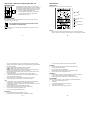
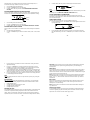
HOW TO INSTALL AND REPLACE THE BATTERIES INTO THE RAIN
SENSOR
The rain sensor works with 2 x AAA, IEC LR3, 1.5V Alkaline batteries. To install and
replace the batteries, please follow the steps below:
1. Press tabs back to unlock rain sensor cover. (Figure 1)
2. Lift rain sensor cover to access battery compartment. (Figure 2)
3. Insert the batteries, observing the correct polarity (see the marking in the battery
compartment). (Figure 3)
4. Replace the battery cover and the rain cover onto the unit.
Note:
In the event of changing batteries in any of the units, all units need to be reset by
following the setting up procedures. This is because a random security code is
assigned by the rain sensor at start-up and this code must be received and stored by
the Weather Center in the first several minutes of power being supplied to it.
Figure 1
Figure 2
Figure 3

9
HOW TO INSTALL AND REPLACE THE BATTERIES INTO THE
WEATHER CENTER
The Weather Center works with 3 x AA, IEC LR6, 1.5V
Alkaline batteries. When the batteries need to be replaced,
the low battery symbol will appear on the LCD. To install
and replace the batteries, please follow the steps below:
1. Remove the battery compartment cover.
2. Insert the batteries observing the correct polarity
(see the marking in the battery compartment).
3. Replace the battery cover.
BATTERY CHANGE:
It is recommended to replace the batteries in all units every 24 months to ensure
optimum accuracy of these units.
Please participate in the preservation of the environment. Return
used batteries to an authorized depot.
Note:
The stored History record will not be kept after the battery change is done on the
Weather Center.
10
FUNCTION KEYS:
Weather Center:
The Weather Center has 5 easy-to-use function keys.
SET key
Press and hold to enter manual setting modes: LCD contrast, Manual time
setting, 12/24 hour time display, Calendar setting, ºF/ ºC temperature unit, Wind
SET
key
+ key
HISTORY key
A
LARM ke
y
MIN/MAX key
11
speed unit, Rainfall unit, Pressure unit, Relative pressure reference setting,
Weather tendency threshold setting, Storm warning threshold setting and Storm
Alarm On/ Off setting
Press to toggle between the display of Mode 1 or Mode 2:
Mode 1: "Wind speed + outdoor temp + rel. pressure"
Mode 2: "Gust + Dew Point temp + rainfall" If pressure is showing with wind
gust, press the plus button to view 24 hour and total rain.
(Mode 2 displayed will be shown for 30 seconds. Then it will return to normal
display automatically.)
In normal display mode, press and hold to switch on/ off the Buzzer
In the weather alarm setting mode, press and hold to adjust different alarm
value and switch the alarm On/ Off
Press to activate the reset mode when max or min record is shown
Stop the alarm during the time alarm or weather alarm ringing
+ key
In display Mode 1, press to toggle between the display of Preset alarm time,
date, weekday + date, Indoor temp, or second in the time display
In display mode 2, press to toggle between the display of Rel. Pressure, 24 hour
rainfall and Total rainfall
Press to adjust (increase) the level of different settings
Stop the alarm during the time alarm or weather alarm ringing
Press to confirm to reset the max/min record
Press to reset the total rainfall amount to 0
HISTORY key
Press to display the weather data history records
Stop the alarm during the time alarm or weather alarm ringing
12
Press to exit manual setting mode and alarm setting mode
ALARM key
Press to enter the time alarm and weather alarm setting mode
Confirm particular alarm setting
Press to exit the manual setting mode
Stop the alarm during the time alarm or weather alarm ringing
Press to exit max/ min record display mode
MIN/MAX key
Press to display minimum and maximum records of various weather data
Press to adjust (decrease) the level of different settings
Stop the alarm during the time alarm or weather alarm ringing
LCD SCREEN
The LCD screen is split into 5 sections displaying the following information:
1. Time and date/ indoor temp/ second
2. Wind data
3. Outdoor temperature, Dew point and humidity,
4. Air pressure, Rainfall data,
5. Air pressure history and Weather forecast icon.

13
Air pressure
histogram
Outdoor temperature
or dew point
in °F or ºC
Wind direction display
and wind speed in
Beaufort scale
Calendar display
Weather tendency
indicator
Time display
Time alarm icon
Outdoor relative
humidity in %
Weather forecast
icon
Relative air pressure
display in inHg o
r
hPa, or total and 24h
rainfall display in inch
or mm
Wind speed or gust in
m
p
h, km/h or m/s
Wind Chill
in °F or °C
Wind speed Hi
alarm icon
Outdoor Humidity
alarm icon
Outdoor temp.
alarm icon
Low battery Indicator (rain sensor)
Low battery Indicator (Thermo-hygro)
Buzzer off indicator
Transmitter signal
reception icon
Low battery Indicator (weather center)
14
* When the signal from the transmitter/ or Rain sensor is successfully received by the
Weather Station, this icon will be switched on. (If not successful, the icon will not be
shown on the LCD). User can therefore easily see whether the last reception was
successful (“ON” icon) or not (“OFF” icon). On the other hand, the short blinking of the
icon shows that a reception is being done at that time.
*In normal display user may press the SET key shortly to toggle between Mode 1 and
Mode 2 display:
Mode 1: Wind speed, outdoor temperature and relative pressure reading are shown.
Wind speed icon
Outdoor temp
icon
Rel Pressure
icon
In Mode 1, this
reception icon is
showing the
condition of the
reception of the
signal from
Thermo-hygro
transmitter
15
Mode 2 : Wind Gust, Dew Point temperature and Rainfall reading are shown.
MANUAL SETTING:
The following manual settings can be changed once the SET key is pressed and hold
for about 2 seconds:
LCD contrast setting
Manual time setting
12/24 hour time display
Calendar setting
°F/ °C temperature unit setting
Wind speed unit
Rainfall unit setting
Air pressure unit setting
Relative pressure reference value setting
Weather tendency threshold value
Wind gust icon
Dew point icon
Rainfall icon
In Mode 2, this
reception icon is
showing the
condition of the
reception of the
signal from Rain
sensor
16
Storm warning threshold value
Storm alarm On/ Off setting
LCD CONTRAST SETTING
The LCD contrast can be set within 8 levels, from "LCD 1" to "LCD 8" (default setting
is LCD 5):
1. Press the SET key, the contrast level digit will start flashing.
2. Use the + or MIN/MAX key to adjust the level of contrast.
3. Confirm with the SET key and enter the MANUAL TIME SETTING.
MANUAL TIME SETTING:
You then may manually set the time of the clock by following the steps below:
1. The hour digit will start flashing.
2. Use the + or MIN/MAX key to set the hour.
3. Press the SET key to switch to the minutes. The minute digit will start flashing.
4. Use the + or MIN/MAX key to set the minute.
5. Confirm the time with the SET key and enter the 12/24 HOUR TIME DISPLAY
SETTING.
Flashing
Minutes flashing
Hou
r
flashing

17
"Date. Month." (for 24h time display)
"Month. Date." (for 12h time display)
A
nnée
12/24 HOUR TIME DISPLAY SETTING:
The time can be set to view as 12-hour or 24-hour format. The default time display
mode is 12-h. To set to 24-h time display:
1. Use the + or MIN/MAX key to toggle the value.
2. Confirm with the SET key and enter the CALENDAR SETTING.
CALENDAR SETTING:
The date default of the Weather Center is 1. 1. of year 2005. The date can be set
manually by proceeding as follows.
1. The year digit starts flashing.
2. Use the + or MIN/MAX key to set the year. The range runs from "00" (2000) to
"99" (2099).
3. Press the SET key to confirm the year and enter the month setting. The month
digit will start flashing.
4. Use the + or MIN/MAX key to set the month.
5. Press the SET key to confirm the month and enter the date setting mode. The
date digit will start flashing.
Digit flashing
18
6. Use the + or MIN/MAX key to set the date.
7. Confirm all calendar settings with the SET key and enter the °F/°C
TEMPERATURE UNIT SETTING.
°F/°C TEMPERATURE UNIT SETTING
The temperature display can be selected to show temperature data in °F or °C.
(default °F)
1. The temperature unit is flashing
2. Use the + or MIN/MAX key to toggle between “°F” or “°C”.
3. Confirm with the SET key and enter the WIND SPEED UNIT SETTING.
WIND SPEED UNIT SETTING
The wind speed unit can be set as mph (mile per hour), km/h (kilometer per hour), or
m/s (meter per second). The default unit is mph.
1. Use the + or MIN/MAX key to toggle between the unit “mph”, “km/h” or “m/s”
2. Confirm with the SET key and enter the RAINFALL UNIT SETTING.
Flashing
Flashing
19
RAINFALL UNIT SETTING
The rainfall unit can be set as inch or mm. The default unit is mm.
1. Use the + or MIN/MAX key to toggle between the unit “inch” or “mm”
2. Confirm the unit with the SET key and enter the RELATIVE AIR PRESSURE
UNIT SETTING
RELATIVE AIR PRESSURE UNIT SETTING
The relative air pressure can be set as inHg or hPa. The default unit is inHg.
1. Use the + or MIN/MAX key to toggle between the unit “inHg" or “hPa”
2. Confirm the unit with the SET key and enter the RELATIVE PRESSURE
REFERENCE VALUE SETTING.
RELATIVE PRESSURE REFERENCE VALUE SETTING
Note:
The default reference pressure value of the barometer is 29.91inHg when batteries
are first inserted. For an exact measurement, it is necessary to first adjust the
barometer to your local relative air pressure (related to elevation above sea
level). Ask for the current atmospheric pressure of your home area (Local weather
service, www, optician, calibrated instruments in public buildings, airport).
Flashing
Flashing
20
The relative air pressure can be manually set to another value within the range of
27.14 to 31.90 inHg (919 to 1080 hPa) for a better reference.
1. The current relative pressure value will start flashing
2. Use the + or MIN/MAX key to increase or decrease the value. Continually
holding the key will allow the value to increase faster.
3. Confirm with the SET key and enter the WEATHER TENDENCY SENSITIVITY
VALUE SETTING.
Note:
This feature is useful for those who live at elevations above sea level, but want their
air pressure display to be based on sea level elevation.
WEATHER TENDENCY SENSITIVITY LEVEL SETTING
You may select a definite switching sensitivity value, .06, .09, or .12 inHg for the
change in the display of weather icons. This represents the "sensitivity" of the weather
forecast (the smaller the value selected, the more sensitive the weather forecast).
Flashing
Flashing
Flashing

21
The default value is 0.09 inHg. Select lower numbers in high humidity areas, i.e.
Oceanside. Select high numbers in arid areas, i.e. Desert.
1. The sensitivity value will start flashing
2. Use the + or MIN/MAX key to select the value.
3. Confirm with the SET key and enter the STORM WARNING SENSITIVITY
SETTING.
STORM WARNING THRESHOLD VALUE SETTING
You may also define a switching sensitivity value for the Storm warning display at a
decrease of air pressure from .09 inHg to .27 inHg over 6 hours (Default 0.15 inHg).
1. The sensitivity value will start flashing.
2. Use the + or MIN/MAX key to select the value.
3. Confirm with the SET key and enter the STORM ALARM ON/OFF SETTING.
STORM ALARM ON/ OFF SETTING
You may also choose to switch On or Off the acoustic Storm warning alarm (Default
OFF).
1. The digit "AOF" will start flashing.
2. Use the + or MIN/MAX key to switch On or Off the alarm. ("AOF" = OFF; "AON"
= On)
Flashing
Flashing
22
A
larm-On icon
3. Confirm with the SET key and the normal display mode will be shown.
Note:
In case a storm warning alarm is activated, the downward weather tendency arrow will
be flashing. (Also see WEATHER TENDENCY INDICATOR below)
TO EXIT THE MANUAL SETTING MODE
To exit the manual setting anytime during the manual setting modes, press the
ALARM key (or HISTORY key) or wait for the automatic timeout. The mode will return
to the normal time display.
TIME ALARM SETTING
The alarm time can be set by the use of the ALARM and SET key.
1. Press the ALARM key once. The “ALARM” icon and time digits are shown at the
top right of the LCD.
2. Press and hold the SET key for about 2 seconds. The hour digit of the alarm
time will start flashing. Press the + or MIN/MAX key to set the hour of the alarm
time.
Flashing
A
larm time digit
23
3. Press the SET key to confirm and advance to the minute setting. The minute
digit will be flashing.
4. Press the + or MIN/MAX key to set the minute of the alarm time. Press the
ALARM key to confirm. Press the HISTORY key or wait for about 30 seconds
and the display will return to normal display mode automatically.
5. In the normal display mode, press the ALARM once key to go to the time alarm
setting mode again. Then press shortly the SET key to switch on or off the time
alarm. (The showing of the icon ((())) means that the time alarm is switched on.)
6. Press the HISTORY key or wait for about 30 seconds and the display will return
to normal display mode automatically.
Note:
The alarm ringing duration is 2 minutes. To stop the alarm, press any key during the
alarm ringing.
Important Note:
After you have followed the aforementioned set-up procedures, you shall read the
main manual for the following important functions of the weather station in details:
Setting Weather alarm
Viewing wind/ rainfall and air pressure data
Viewing Max/ Max weather data
Viewing History data record
Mounting the units:
Using 915MHz wireless transmission gives users little restriction on placement as that
all units can be positioned virtually anywhere to within a 330 ft radius of the base
station. Please ensure that the cable included in this set meets with your distance
requirements (see accessories in the main user manual for adding extension cables).
24
Important: Ensure all signals can be received and/or all cable distances meet with
your requirements at the point of fixing particularly before you start drilling any
mounting holes.
Wind sensor
Secure the main unit to the shaft of the mast holder using the single screw provided
with the front of the sensor (marked E) facing in the East-West direction otherwise
wind direction will not be accurate. Now fix the entire unit to a suitable mast using the
U-bolt, washers and nuts found in this set.
Note: For best results mount the wind sensor onto a mast to allow the wind to freely
travel from all directions to enable an accurate reading (ideal mast size should be
from Ø
5
/
8
” to 1
1
/
4
”). Ensure that the cable of the wind sensor meets your distance
requirements
Rain sensor
The rain sensor should be mounted horizontally about 2-3ft off from the ground (or
higher) in an open area away from trees or other coverings to allow rain to fall
naturally for an accurate reading.
Note: For best results ensure the base is horizontal to allow maximum drainage of
any collected rain
Thermo-hygro Sensor
To wall mount the thermo-hygro sensor, fix the wall holder onto the desired wall (2
screws are supplied), plug the sensor firmly into the wall holder and then carefully
replace the rain cover back over the thermo-hygro sensor.

25
Note: After mounting the units, should the weather data not be received, user may
need to remove the batteries from all units and redo the set-up procedures after about
5 minutes.
WARRANTY INFORMATION
La Crosse Technology, Ltd provides a 1-year limited warranty on this product against
manufacturing defects in materials and workmanship.
This limited warranty begins on the original date of purchase, is valid only on products
purchased and used in North America and only to the original purchaser of this
product. To receive warranty service, the purchaser must contact La Crosse
Technology, Ltd for problem determination and service procedures. Warranty service
can only be performed by a La Crosse Technology, Ltd authorized service center.
The original dated bill of sale must be presented upon request as proof of purchase to
La Crosse Technology, Ltd or La Crosse Technology, Ltd’s authorized service center.
La Crosse Technology, Ltd will repair or replace this product, at our option and at no
charge as stipulated herein, with new or reconditioned parts or products if found to be
defective during the limited warranty period specified above. All replaced parts and
products become the property of La Crosse Technology, Ltd and must be returned to
La Crosse Technology, Ltd.
Replacement parts and products assume the remaining original warranty, or ninety
(90) days, whichever is longer. La Crosse Technology, Ltd will pay all expenses for
labor and materials for all repairs covered by this warranty. If necessary repairs are
not covered by this warranty, or if a product is examined which is not in need or repair,
you will be charged for the repairs or examination.
26
The owner must pay any shipping charges incurred in getting your La Crosse
Technology, Ltd product to a La Crosse Technology, Ltd authorized service center.
La Crosse Technology, Ltd will pay ground return shipping charges to the owner of
the product to a USA address only.
Your La Crosse Technology, Ltd warranty covers all defects in material and
workmanship with the following specified exceptions: (1) damage caused by accident,
unreasonable use or neglect (including the lack of reasonable and necessary
maintenance); (2) damage occurring during shipment (claims must be presented to
the carrier); (3) damage to, or deterioration of, any accessory or decorative surface; (4)
damage resulting from failure to follow instructions contained in your owner’s manual;
(5) damage resulting from the performance of repairs or alterations by someone other
than an authorized La Crosse Technology, Ltd authorized service center; (6) units
used for other than home use (7) applications and uses that this product was not
intended or (8) the products inability to receive a signal due to any source of
interference.
This warranty covers only actual defects within the product itself, and does not cover
the cost of installation or removal from a fixed installation, normal set-up or
adjustments, claims based on misrepresentation by the seller or performance
variations resulting from installation-related circumstances.
LA CROSSE TECHNOLOGY, LTD WILL NOT ASSUME LIABILITY FOR
INCIDENTAL, CONSEQUENTIAL, PUNITIVE, OR OTHER SIMILAR DAMAGES
ASSOCIATED WITH THE OPERATION OR MALFUNCTION OF THIS PRODUCT.
THIS PRODUCT IS NOT TO BE USED FOR MEDICAL PURPOSES OR FOR
PUBLIC INFORMATION. THIS PRODUCT IS NOT A TOY. KEEP OUT OF
CHILDREN’S REACH.
27
This warranty gives you specific legal rights. You may also have other rights specific
to your State. Some States do no allow the exclusion of consequential or incidental
damages therefore the above exclusion of limitation may not apply to you.
For warranty work, technical support, or information contact:
La Crosse Technology, Ltd
2809 Losey Blvd. S.
La Crosse, WI 54601
Phone: 608.782.1610
Fax: 608.796.1020
e-mail:
support@lacrossetechnology.com
(warranty work)
sales@lacrossetechnology.com
(information on other products)
web:
www.lacrossetechnology.com
For more information, please visit:
www.lacrossetechnology.com
All rights reserved. This handbook must not be reproduced in any form, even in excerpts, or
duplicated or processed using electronic, mechanical or chemical procedures without written
permission of the publisher.
28
This handbook may contain mistakes and printing errors. The information in this handbook is
regularly checked and corrections made in the next issue. We accept no liability for technical
mistakes or printing errors, or their consequences.
All trademarks and patents are acknowledged.
-
 1
1
-
 2
2
-
 3
3
-
 4
4
-
 5
5
-
 6
6
-
 7
7


La Crosse Technology TX31U-IT User manual
- Category
- Weather stations
- Type
- User manual
Ask a question and I''ll find the answer in the document
Finding information in a document is now easier with AI
Related papers
-
 La Crosse Technology WS-1515U-IT User manual
-
La Crosse WS-1516-IT Owner's manual
-
 La Crosse Technology WS-1510-IT User manual
-
La Crosse WS-1510U-IT User manual
-
 La Crosse Technology WS-1612 Operating instructions
-
 La Crosse Technology WS-1611 Operating instructions
-
 La Crosse Technology WS-2810U-IT User manual
-
 La Crosse Technology WS-2811U-IT Operating instructions
-
 La Crosse Technology WS-2811U-IT Operating instructions
-
 La Crosse Technology wireless weather station User manual