Page is loading ...

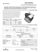
36J22, 36J24, 36J54 and 36J55
DSI and HSI Single and Two Stage
Combination Gas Valves
INSTALLATION INSTRUCTIONS
Operator: Save these instructions for future use!
The 36J22/24/54/55 combination gas valves are de-
signed for direct spark ignition (DSI) and hot surface
ignition (HSI) system applications. These valves
are equipped with redundant and main solenoid
valves that control gas ow to the main burners, a
pressure regulator and a two-position on/o switch
for regulation and electrical shut-o of the solenoid
valves. The 36J24 and 36J55 are also equipped
with a slow-opening pressure regulator for softer
lighting characteristics. When the second solenoid
on 2-stage valves is energized the valve operates
at the second stage (high) outlet pressure setting.
Type of Gas: Natural gas
LP gas (use conversion kit)
Ambient Temperature: -40° to 175°F
Pressure Rating: 14" W.C. (½ PSI) max.
Voltage: 24 VAC
Frequency: 50/60 Hz
Current: Single Stage – 0.28A
Two-Stage – 0.43A
Mounting Positions: Multipoise – Control may
be mounted in any position
CONTENTS
Description ........................................................ 1
Specications .................................................... 1
Precautions ....................................................... 2
Installation
System Wiring ...................................... 3
Adjustment
Pressure Regulator Adjustment ............ 6
Lighting Instructions .......................................... 8
Contents French ................................................ 9
Contents Spanish ............................................ 17
36J Two-Stage
36J Single Stage
PIPE SIZES/CAPACITIES
Pipe Sizes
Available
(inches)
1
/2" x
1
/2" NPT 140,000
AGA Std. Nat. Gas
(1,000 BTU/cu. ft.)
226,800
LP Gas
(2,500 BTU/cu. ft.)
Capacity (BTU/hr) at
1” pressure drop across valve
Fig. 1
FAILURE TO READ AND FOLLOW ALL INSTRUCTIONS CAREFULLY
BEFORE INSTALLING OR OPERATING THIS CONTROL COULD CAUSE
PERSONAL INJURY AND/OR PROPERTY DAMAGE.
SPECIFICATIONS
DESCRIPTION
PART NO. 37-7338A
1224
www.white-rodgers.com
www.emersonclimate.com
Model
Number
Coil
Voltage
Stages
Opening
Characteristics
Intermittent Pilot
Proven Pilot
HSI DSI
Standing
Pilot
36J22 24V 1 Fast No Yes Yes No
36J24 24V 1 Slow No Yes Yes No
36J54 24V 2 Fast No Yes Yes No
36J55 24V 2 Slow No Yes Yes No
Pressure Regulator Adjustment Range (in W.C.)
Two Stage
Gas
Type
Single
Stage
Low High
Min. Di.
Low to High
Natural 2.5 – 5.0 1.0 – 4.0 2.0 – 5.0 1
LP 7.0 – 12.0 4.0 – 10.0 6.0 – 12.0 2

2
PRECAUTIONS
SPECIFICATIONS
1. Failuretoturnoelectricormaingas
supply to heating system could cause
personal injury and/or property damage
byshock,gassuocation,re,and/or
explosion.
2. Do not use this control on circuits
exceedingspeciedvoltage.Higher
voltage will damage the control and may
causeshockorrehazard.
3. NEVER USE FLAME OR ANY KIND OF
SPARK TO CHECK FOR GAS LEAKS–
COULD CAUSE FIRE AND/OR EXPLOSION.
4. Do not use a control set for natural gas
with LP gas, or a control set for LP gas
with natural gas. Personal injury and/or
Ifyoudonotfollowtheseinstructionsexactly,areorexplosion
may result, causing property damage, personal injury or loss of life.
propertydamage,gassuocation,re,
and/or explosion may result.
5. Do not use a gas valve which appears to be
damaged. A damaged valve may cause
personal injury and/or property damage
duetoshock,gassuocation,reand/or
explosion. Contact supplier to replace any
valve that appears to have been damaged.
6. Do not use a gas valve that has been in
direct contact with water. Water entering
gas valve may result in concealed internal
damage to gas valve. Personal injury and/
orpropertydamage,gassuocation,re
and/or explosion may result.
WARNING
!
DO NOT BEGIN INSTALLATION UNTIL YOU READ THE FOLLOWING
PRECAUTIONS.
WARNING
!
Properly install gas piping to control.
• Donotremoveprotectiveinletoroutletcapsuntilreadytoconnectsupplypipetogasvalve.
• Usenewsupplypipe,properlythreaded,reamed,de-burred,andcleaned.
• Usebackupwrench,appliedonlytoprovidedwrenchatsoninletboss,whentighteningthe
supply pipe. Do not grip bracket, solenoid or any other part of control.
• Donotover-tightenpipetocontrol(50ft-lbs max.)
• Alwaysinstallsedimenttrapinthegassupplylinetopreventcontaminationofgasvalve.
Failuretoinstallproperlycancausegasleakageresultingininjuryduetoreorexplosion.
CAUTION
!
1. Do not short out terminals on gas valve or primary control to test. Short or incorrect wiring
can cause equipment damage, property damage, and/or personal injury.
2. This control is not intended for use in locations where it may come in direct contact with water.
Suitable protection must be provided to shield the control from exposure to water (dripping,
spraying, rain, etc.).
3. Cleangaspipingofcontaminants,cuttinguid,orotherchemicalswhichmightreactharm-
fully with the gas valve components before install.
Parts and Accessories:
Natural to Regulated LP Gas Conversion Kits
• F92-0659 for Single Stage
• F92-1008 for Two-Stage
Natural to Unregulated LP Gas Conversion Kit
• F92-0737
LP to Natural Gas Conversion Kits
• F92-0656 for Single Stage
• F92-1011 for Two-Stage
Note: Two single stage kits may be used for two-
stage valve

3
1. Turn o electrical power to the system at the
fuse box or circuit breaker. Also turn o the
main gas supply.
2. If replacing an existing valve, disconnect all
plumbing and electrical connections from the
old control.
3. The control may be installed in any position.
The arrow on the bottom plate indicates the
direction of inlet gas ow.
4. You should use new pipe that is properly
chamfered, reamed, and free of burrs and
chips. If you are using old pipe, be sure it is
clean and free of rust, scale, burrs, chips, and
old pipe joint compound.
5. Apply pipe joint compound (pipe dope) that
is approved for all gases, only to the male
threads of the pipe joints. DO NOT apply
compound to the rst two threads (see gure
2 for typical piping connections).
6. If you are using a vise or open-end wrench to
hold the valve while installing piping, do not
tighten excessively, as this may damage the
valve. (Torque: 375 in-lb maximum.) Do not
cross-thread during installation as this may
damage the valve.
7. See SYSTEM WIRING when making electrical
connections. After all gas and electrical con-
nections are completed, turn gas on and check
for gas leaks with leak detection solution or
soap suds. Bubbles forming indicate a leak.
SHUT OFF GAS AND FIX ALL
LEAKS IMMEDIATELY.
LP GAS CONVERSION
For LP gas conversion, use the LP conversion kit
supplied with this control. Refer to the instruc-
tions packed with LP conversion kit.
Fig. 2 – Typical Gas Valve Piping
Piped Gas
Supply
Piped Gas
Supply
Tubing Gas
Supply
NOTE: ALWAYS INCLUDE A
DRIP LEG IN PIPING
Figure 2. Typical gas valve piping
NOTE: A MANUAL SHUTOFF VALVE
MUST BE INSTALLED WITHIN
6 FEET OF THE EQUIPMENT
Horizontal
Drop
3 in.
minimum
Gas Valve
Gas Valve
Riser
3 in.
minimum
Drop
Horizontal
Riser
Gas Valve
3 in.
minimum
INSTALLATION
MAIN PIPING CONNECTIONS
NOTE
Refer to warnings and cautions on page 2 before
attempting installation. All piping must comply
with local codes, ordinances, and/or national
fuel gas codes.
NOTE
All piping must comply with local codes, ordinances,
and/or national fuel gas codes.
Gas Flow
Direction

4
Outlet Pressure Post
Set Screw: 3/32” Hex Head
(.339 Dia. + DFT.)
Accepts 5/16” Hose Connection
Low Fire Regulator
Cover Screw
(Reg. Adj. Beneath
the Screw)
3/16” x .032” Thick Male
Spade Terminal (1)
1/4” x .032” Thick Male
Spade Terminals (3)
3/16” Ground Terminal
Control I.D. Label
Inlet Pressure Post
Set Screw: 3/32” Hex Head
(.339 Dia. + DFT.)
Accepts 5/16” Hose Connecon
4.693” Inlet to Outlet
On/Off Switch
High Fire Regulator
Cover Screw
(Reg. Adj. Beneath
the Screw)
Outlet Pressure Post
.339 Dia. +DFT.
(Set Screw: 3/32” Hex Head)
Accept 5/16” ID Hose Connection
Regulator Cover Screw
(Reg. Adj. Beneath This Screw)
3/16” Ground Terminal
Control I.D. Label
1/4” x .032” THK. Male
Spade Terminals (2)
Inlet Pressure Post
.339 Dia. +DFT.
(Set Screw: 3/32” Hex Head)
Accept 5/16” I.D. Hose
Connecon
4.693” Inlet to Outlet
On/Off
Switch
Fig. 4 – Two-Stage Valve Features, Terminals and Wiring
On/Off
Switch
Hi
M
Main and
Redundant
Valves (Low Fire)
2nd Stage
Valve (High Fire)
C
C
INSTALLATION
Fig. 3 – Single Stage Valve Features, Terminals and Wiring
On/Off
Switch
Main and
Redundant
Valves
SYSTEM WIRING
REFER TO AND FOLLOW THE APPLIANCE
MANUFACTURER'S WIRING DIAGRAM.
REFER TO FIGURES 3 AND 4 FOR TERMINAL
IDENTIFICATION.
NOTE
All wiring should be installed according to local
and national electrical codes and ordinances.
Always check that the electrical power supply
used agrees with the voltage and frequency
shown on the gas control.

5
Fig. 6 – Typical Wiring for Hot Surface Ignition System
Fig. 7 – Typical Wiring for Direct Spark Ignition System, Single Stage Valve
M – Main
1/4" Female Receptacle
This end plug
to Furnace
3-pin connector
To new
gas valve
Black
Red
Hi – High
3/16" Female Receptacle
White
C – Common
1/4" Female Receptacle
Fig. 5 – Wire Harness Adapter
If system requires 3-pin connector for 2-stage valve, use wire harness adapter, see gure 5
INSTALLATION
M
V
2
T
R
G
N
D
T
H
M
V
1
L
2
F
P
L
1
H
S
1
THERMOSTAT OR
CONTROLLER
ALTERNATE
LIMIT
L1
(HOT)
L2
LIMIT
CONTROLLER
FLAME
PROBE
RED
ADAPTER
BLUE
HOT
SURFACE
IGNITER
MV2
MV1
BURNER
GROUND
H
S
2
TRANSFORMER
GAS
VALVE
ALTERNATE
LIMIT
TRANSFORMER
THERMOSTAT OR
CONTROLLER
L1 (HOT)
L2
SPARK
PROBE
MV
(GND)
LIMIT
CONTROLLER
FLAME
GAS
VALVE
MV
VAL
TR
TH
GND
FLY
LEAD
SPARK
Burner Ground
FLAME
PROBE
(GND)

6
Regulator Cover Screw
Regulator
Cover Screw
Plastic
Adjust Screw
Regulator
Spring
Plastic Adjust Screw
Regulator Spring
Two-Stage Valve
Single Stage Valve
ADJUSTMENT
Fig. 8
PRESSURE REGULATOR
ADJUSTMENT
These controls are shipped from the factory set
for Natural Gas with the regulator set as specied
on the control label. Consult the appliance rating
plate to ensure burner manifold pressure is as
specied. If another outlet pressure is required,
follow these steps. For LP gas conversion, use LP
conversion kit.
NOTE
NATURAL GAS
Single Stage Models – Outlet pressure will be
factory-adjusted in the 2.5" to 5" range. The valve
cannot be adjusted outside this range.
Two-Stage Models: Low outlet pressure will be
factory- adjusted in the 1 to 4" W.C. range and
high outlet pressure will also be factory-adjusted
in the 2 to 5" W.C. range.
The valve cannot be adjusted outside this range
and the high outlet pressure setting must always
be set at least 1" above the low outlet pressure
setting.
OUTLET PRESSURE ADJUSTMENT
1. Turn o all electrical power to the system.
2. Back outlet pressure test screw out one turn,
counterclockwise, not more than one turn.
(see g. 8)
3. Attach a hose and manometer to the outlet
pressure boss of the valve.
4. Turn on system power. Set thermostat to call
for heat (low stage for two-stage systems).
Main burner should light. Proceed to step 7 for
single stage systems.
5. (2-stage only) Remove regulator cover screw
from the low outlet pressure regulator adjust
tower (g. 8) and turn screw clockwise
( ) to increase pressure, or counterclock-
wise ( ) to decrease pressure. Always
adjust regulator according to original equip-
ment manufacturer's specications listed on
the appliance rating plate. Replace regulator
cover screw.
6. (2-stage only) Set thermostat to call for high
stage.
7. Remove regulator cover screw from the single
stage or high outlet pressure regulator adjust
tower (g. 8) and turn screw clockwise
( ) to increase pressure, or counterclock-
wise ( ) to decrease pressure. Always
adjust regulator according to original equip-
ment manufacturer's specications listed on
the appliance rating plate. Replace regulator
cover screw.
8. Turn o all electrical power to the system.
9. Remove manometer hose and turn outlet
pressure test screw in to seal pressure port
(clockwise, 7 in-lb minimum).
10. Turn on electrical power to the system.
11. Turn on system power and energize valve.
12. Using a leak detection solution or soap suds,
check for leaks at pressure boss screw. Bubbles
forming indicate a leak. SHUT OFF GAS AND
FIX ALL LEAKS IMMEDIATELY.

7
FOR YOUR SAFETY READ BEFORE OPERATING
OPERATING INSTRUCTIONS
A. This appliance does not have a pilot. It is equipped
with an ignition device which automatically lights the
burner. Do not try to light the burner by hand.
B. BEFORE OPERATING smell all around the appli-
ance area for gas. Be sure to smell next to the oor
because some gas is heavier than air and will settle
on the oor.
FOR YOUR SAFETY
“WHAT TO DO IF YOU SMELL GAS”
• Donottrytolightanyappliance.
• Donottouchanyelectricalswitch;donotuse
any phone in your building.
1. STOP! Read the safety information above on this
page.
2. Set the thermostat to lowest setting.
3. Turn o all electric power to the appliance.
4. This appliance is equipped with an ignition device
which automatically lights the burner. Do not try
to light the burner by hand.
5. Remove control access panel.
6. Wait ve (5) minutes to clear out any gas. If you
then smell gas, STOP! Follow “B” in the safety
information above on this page. If you don’t smell
gas, go to the next step.
7. Push gas control switch to “ON.”
NOTE: Do not force.
8. Replace control access panel.
9. Turn on all electric power to the appliance.
10. Set thermostat to desired setting.
11. If the appliance will not operate, follow the in-
structions “To Turn O Gas To Appliance” and call
your service technician or gas supplier.
TO TURN OFF GAS TO APPLIANCE
1. Set the thermostat to lowest setting.
2. Turn o all electric power to the appliance if
service is to be performed.
3. Remove control access panel.
4. Push gas control switch to “OFF.” Do not force.
5. Replace control access panel.
• Immediatelycallyourgassupplierfromaneigh-
bor’s phone. Follow the gas supplier’s instructions.
• Ifyoucannotreachyourgassupplier,callthe
redepartment.
C. Use only your hand to move the gas control
switch. Never use tools. If the switch will not
move by hand, don’t try to repair it, call a qualied
service technician. Force or attempted repair may
result in a re or explosion.
D. Do not use this appliance if any part has been
under water. Immediately call a qualied service
technician to inspect the appliance and to replace
any part of the control system and any gas control
which has been under water.
WARNING
!
If you do not follow these instructions exactly, a fire or explosion
may result causing property damage, personal injury or loss of life.
LIGHTING INSTRUCTIONS

White-Rodgers is a business
of Emerson Electric Co.
The Emerson logo is a
trademark and service mark
of Emerson Electric Co.
www.white-rodgers.com
www.emersonclimate.com

White-Rodgers est une entreprise
d’Emerson Electric Co.
Le logo d’Emerson est une marque
de commerce et une marque de
service d’Emerson Electric Co.
www.white-rodgers.com
www.emersonclimate.com
/