Ultra Start 1172 is an advanced remote starter and vehicle security system that offers a wide range of features to enhance the convenience, security, and comfort of your vehicle. With its programmable settings and customizable outputs, the Ultra Start 1172 can be tailored to meet your specific needs and preferences.
Some of the key capabilities of the Ultra Start 1172 include:
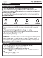
- Remote start: Start your vehicle from the comfort of your home or office with the included 2-button remote transmitter.
- Door lock/unlock: Lock and unlock your vehicle's doors remotely with the same transmitter.
- Trunk release: Pop your trunk remotely with the included remote transmitter.
Ultra Start 1172 is an advanced remote starter and vehicle security system that offers a wide range of features to enhance the convenience, security, and comfort of your vehicle. With its programmable settings and customizable outputs, the Ultra Start 1172 can be tailored to meet your specific needs and preferences.
Some of the key capabilities of the Ultra Start 1172 include:
- Remote start: Start your vehicle from the comfort of your home or office with the included 2-button remote transmitter.
- Door lock/unlock: Lock and unlock your vehicle's doors remotely with the same transmitter.
- Trunk release: Pop your trunk remotely with the included remote transmitter.


-
 1
1
-
 2
2
-
 3
3
-
 4
4
-
 5
5
-
 6
6
-
 7
7
-
 8
8
-
 9
9
-
 10
10
-
 11
11
-
 12
12
-
 13
13
-
 14
14
-
 15
15
-
 16
16


Ultra Start 1172 is an advanced remote starter and vehicle security system that offers a wide range of features to enhance the convenience, security, and comfort of your vehicle. With its programmable settings and customizable outputs, the Ultra Start 1172 can be tailored to meet your specific needs and preferences.
Some of the key capabilities of the Ultra Start 1172 include:
- Remote start: Start your vehicle from the comfort of your home or office with the included 2-button remote transmitter.
- Door lock/unlock: Lock and unlock your vehicle's doors remotely with the same transmitter.
- Trunk release: Pop your trunk remotely with the included remote transmitter.
Ask a question and I''ll find the answer in the document
Finding information in a document is now easier with AI
Related papers
-
Ultra Start 1655XR User manual
-
-
-
-
Ultra Start 32xx Series User manual
-
-
-
-
-
Other documents
-
Soundstream TARANTULA RS.2 Installation guide
-
 CrimeStopper cool start RS2-G3 Installation Instructions Manual
-
 Crime Stopper RS4-G5 Installation guide
-
TEAC 35XX User manual
-
Soundstream TARANTULA RS.3 Installation guide
-
 Doberman Security SE-0119 re User manual
-
Bulldog Security RS92 Owner's manual
-
 CrimeStopper Cool Start RS-1 Installation Instructions Manual
-
-


