MQ Multiquip JB11090 User manual

Category
Water pumps
Type
User manual
OPERATION AND PARTS MANUAL
THIS MANUAL MUST ACCOMPANY THE EQUIPMENT AT ALL TIMES.
To find the latest revision of this
publication, visit our website at:
www.multiquip.com
JIMMY SERIES
MODELS:
JB5135, JB7135, JB5090, JB7090,
JB8090, JB9180, JB11090
HYDRAULIC REBAR BENDERS
MODEL JPU1
ELECTRIC-HYDRAULIC PUMP
Revision #9 (01/04/08)
JIMMY SERIES HYDRAULIC REBAR BENDERS — OPERATION AND PARTS MANUAL — REV. #9 (01/04/08) — PAGE 2
Grinding/cutting/drilling of masonry, concrete, metal and
other materials with silica in their composition may give
off dust or mists containing crystalline silica. Silica is a
basic component of sand, quartz, brick clay, granite and
numerous other minerals and rocks. Repeated and/or
substantial inhalation of airborne crystalline silica can
cause serious or fatal respiratory diseases, including
silicosis. In addition, California and some other
authorities have listed respirable crystalline silica as a
substance known to cause cancer. When cutting such
materials, always follow the respiratory precautions
mentioned above.
WARNING
Grinding/cutting/drilling of masonry, concrete, metal and
other materials can generate dust, mists and fumes
containing chemicals known to cause serious or fatal
injury or illness, such as respiratory disease, cancer,
birth defects or other reproductive harm. If you are
unfamiliar with the risks associated with the particular
process and/or material being cut or the composition of
the tool being used, review the material safety data
sheet and/or consult your employer, the material
manufacturer/supplier, governmental agencies such as
OSHA and NIOSH and other sources on hazardous
materials. California and some other authorities, for
instance, have published lists of substances known to
cause cancer, reproductive toxicity, or other harmful
effects.
Control dust, mist and fumes at the source where
possible. In this regard use good work practices and
follow the recommendations of the manufacturers or
suppliers, OSHA/NIOSH, and occupational and trade
associations. Water should be used for dust
suppression when wet cutting is feasible. When the
hazards from inhalation of dust, mists and fumes cannot
be eliminated, the operator and any bystanders should
always wear a respirator approved by NIOSH/MSHA for
the materials being used.
WARNING
SILICOSIS WARNING RESPIRATORY HAZARDS
JIMMY SERIES HYDRAULIC REBAR BENDERS — SILICOSIS WARNING
JIMMY SERIES HYDRAULIC REBAR BENDERS — OPERATION AND PARTS MANUAL — REV. #9 (01/04/08) — PAGE 3
JIMMY SERIES HYDRAULIC REBAR BENDERS — TABLE OF CONTENTS
Specification and part number
are subject to change without
notice.
NOTE
NOTE
As a continuing effort to
update our parts book,
contact the MULTIQUIP
literature department for the
latest revision of your
"Operation and Parts
Manual"
Multiquip Jimmy Series
Hydraulic Rebar Benders
Silicosis Warning ....................................................... 2
Table Of Contents ..................................................... 3
Parts Ordering Procedures ....................................... 4
Safety Message Alert Symbols ................................. 5
Rules For Safe Operation ...................................... 6-8
Specifications (Rebar Unit) ....................................... 9
Specifications (Pump) ............................................. 10
General Information ........................................... 11-12
Components............................................................ 13
Inspection ................................................................ 14
Applying Power ....................................................... 15
Operation ........................................................... 16-19
Shut-Down .............................................................. 19
Maintenance ........................................................... 20
Explanation Of Code In Remarks Column .............. 22
Suggested Spare Parts ........................................... 23
Nameplate and Decals....................................... 24-25
JB5135 Assembly ............................................. 26-27
JB7135 Assembly ............................................. 28-29
JB5090 Assembly ............................................. 30-31
JB7090 Assembly ............................................. 32-33
JB8090 Assembly ............................................. 34-35
JB9180 Assembly ............................................. 36-37
JB11090 Assembly ........................................... 38-39
Electric Pump Assembly..................................... 40-41
Control Valve Assembly...................................... 42-43
Terms and Conditions of Sale ................................. 44
JIMMY SERIES HYDRAULIC REBAR BENDERS — OPERATION AND PARTS MANUAL — REV. #9 (01/04/08) — PAGE 4
www.multiquip.com
Ordering parts has never been easier!
Choose from three easy options:
WE ACCEPT ALL MAJOR CREDIT CARDS!
When ordering parts, please supply:
Dealer Account Number
Dealer Name and Address
Shipping Address (if different than billing address)
Return Fax Number
Applicable Model Number
Quantity, Part Number and Description of Each Part
Specify Preferred Method of Shipment:
UPS/Fed Ex
DHL
Priority One
Tr uck
Ground
Next Day
Second/Third Day
All orders are treated as
Standard Orders
and will ship the same day if received prior
to 3PM PST.
If you have an MQ Account, to obtain a
Username and Password, E-mail us at:
To obtain an MQ Account, contact your
District Sales Manager for more information.
Order via Internet (Dealers Only):
Order parts on-line using Multiquip’s SmartEquip website!
View Parts Diagrams
Order Parts
Print Specification Information
Note: Discounts Are Subject To Change
Goto www.multiquip.com and click on
Order Parts
to log in and save!
Use the
internet
and qualify for a 5% Discount
on
Standard orders
for all orders which include
complete part numbers.*
Order via Fax (Dealers Only):
All customers are welcome to order parts via Fax.
Domestic (US) Customers dial:
1-800-6-PARTS-7 (800-672-7877)
Fax
your order in and qualify for a 2% Discount
on
Standard orders
for all orders which include
complete part numbers.*
Order via Phone:
Domestic (US) Dealers Call:
1-800-427-1244
Best Deal!
International Customers
should contact
their local Multiquip Representatives for
Parts Ordering information.
Non-Dealer Customers:
Contact your local Multiquip Dealer for
parts or call 800-427-1244 for help in
locating a dealer near you.
Note: Discounts Are Subject To Change
Effective:
January 1
st
, 2006
PARTS ORDERING PROCEDURES
JIMMY SERIES HYDRAULIC REBAR BENDERS — OPERATION AND PARTS MANUAL — REV. #9 (01/04/08) — PAGE 5
JIMMY SERIES HYD. REBAR BENDERS— SAFETY MESSAGE ALERT SYMBOLS
NOTE
SAFETY MESSAGE ALERT SYMBOLS
The three (3) Safety Messages shown below will inform you
about potential hazards that could injure you or others. The
Safety Messages specifically address the level of exposure
to the operator, and are preceded by one of three words:
DANGER, WARNING, or CAUTION.
HAZARD SYMBOLS
Potential hazards associated with the operation of the
Jimmy
Series Hydraulic Rebar Benders and Electric Hydraulic
Pump
will be referenced with Hazard Symbols which appear
throughout this manual, and will be referenced in conjunction
with Safety Message Alert Symbols.
You WILL be
KILLED
or
SERIOUSLY
injured if you DO
NOT follow directions.
DANGERDANGER
DANGERDANGER
DANGER
You CAN be
INJURED
if you DO NOT follow directions.
CAUTION
CAUTIONCAUTION
CAUTIONCAUTION
CAUTION
This Operation and Parts Manual
has been developed to provide
complete instructions for the safe
and efficient operation of the
Jimmy
Series Hydraulic Rebar Bender
and Electric-Hydraulic Pump.
Before using this hydraulic rebar bender and pump, ensure
that the operating individual has read and understands all
instructions in this manual.
Safety precautions should be followed at all times when operating
this equipment. Failure to read and understand the Safety
Messages and Operating Instructions could result in injury to
yourself and others.
FOR YOUR SAFETY AND THE SAFETY OF OTHERS!
ALWAYS wear approved
respiratory
protection when required.
WARNING - Respiratory Hazards
ALWAYS wear approved eye and
hearing protection.
CAUTION - Eye and Hearing Hazards
ALWAYS place the power control unit's
ON/OFF switch in the OFF position when
the rebar bender is not in use.
CAUTION - Accidental Starting Hazards
Other important messages are provided throughout this
manual to help prevent damage to your rebar bender, other
property, or the surrounding environment.
CAUTION - Equipment Damage Hazards
You CAN be
KILLED
or
SERIOUSLY
injured if you DO
NOT follow directions.
WARNINGWARNING
WARNINGWARNING
WARNING
JIMMY SERIES HYDRAULIC REBAR BENDERS — OPERATION AND PARTS MANUAL — REV. #9 (01/04/08) — PAGE 6
JIMMY SERIES HYDRAULIC REBAR BENDERS — RULES FOR SAFE OPERATION
The following safety guidelines should always be used when
operating the
Jimmy Series Hydraulic Rebar Bender and
Electric-Hydraulic Pump.
GENERAL SAFETY
DO NOT operate or service this
equipment before reading this entire
manual.
This equipment should not be operated by persons under
18 years of age.
NEVER operate this equipment without proper protective
clothing, shatterproof glasses, steel-toed boots, hard hat
and other protective devices required by the job.
NEVER operate this equipment under the influence of
drugs
or
alcohol
.
NEVER operate this equipment when not feeling
well due to fatigue, illness or taking medicine.
NEVER operate the rebar bender in an
explosive atmosphere or near
combustible materials. The possibility
exists of the rebar bender emitting a spark
during operation. A explosion or fire could
result causing severe
bodily harm or
even death if the sparks make contact with combustible
or explosive materials.
Maintain this equipment in a safe operating condition at
all times.
Keep bystanders, children and visitors away while
operating the rebar bender. Distractions can cause you
to lose control.
DO NOT wear loose clothing or jewelry. Contain long hair.
Keep your hair, clothing, and gloves away from moving
parts.
ALWAYS store equipment properly when it is not being
used. Equipment should be stored in a clean, dry location
out of the reach of children.
ALWAYS be sure the operator is familiar with proper
safety precautions and operation techniques before using
rebar bender.
ALWAYS keep work area clean and free of foreign matter
and debris. Also keep work area well lit.
NEVER leave the rebar bender unattended. When not in
use always unplug the rebar bender from power source.
Keep all
inexperienced
and
unauthorized
people away
from the equipment at all times.
Become familiar with the components of the rebar bender
before operating.
Use this rebar bender only for its intended purpose. DO
NOT use this rebar bender for applications not
recommended.
Inspect the rebar bender after each use. Replace any
damaged or worn parts immediately. DO NOT use a
defective rebar bender.
If a malfunction occurs, immediately unplug the rebar
bender from the power source and correct the problem. If
the problem can not be corrected, contact your nearest
MQ service center.
All WARNING statements must be carefully observed to
help prevent personal injury.
ALWAYS wear proper respiratory (mask),
hearing and eye protection equipment when
operating the rebar bender.
ALWAYS replace any worn or damaged warning decals.
Manufacturer does not assume responsibility for any
accident due to equipment modifications.
NEVER use accessories or attachments, which are not
recommended by Multiquip for this equipment. Damage
to the equipment and/or injury to user may result.
DANGERDANGER
DANGERDANGER
DANGER
Failure to follow instructions in this manual may lead to
serious injury or even death! This equipment is to be
operated by trained and qualified personnel only! This
equipment is for industrial use only.
Read this manual!
JIMMY SERIES HYDRAULIC REBAR BENDERS — OPERATION AND PARTS MANUAL — REV. #9 (01/04/08) — PAGE 7
JIMMY SERIES HYDRAULIC REBAR BENDERS — RULES FOR SAFE OPERATION
UNIT SAFETY INSTRUCTIONS
All hose connections must be tightened with the proper
tools before operating hydraulic power unit. DO NOT over
tighten. Connections should only be tightened securely
and leak-free. Over tightening can cause premature thread
failure or high-pressure fittings to split at pressures lower
than their rated capacities.
Should a hydraulic hose ever rupture, burst, or need to
be disconnected, immediately shut off the pump and
release all pressure. NEVER attempt to grasp a leaking
pressurized hose with your hands. The force of escaping
hydraulic fluid could cause serious injury.
NEVER subject the hose to potential hazard such as
fire, sharp surfaces, extreme heat or cold, or heavy
impact. DO NOT allow the hose to kink, twist curl, crush,
cut, or bend so tightly that the fluid flow within the hose
is blocked or reduced. Periodically inspect the hose for
wear, because any of these conditions can damage the
hose and possibly result in personal injury.
NEVER use the hose to move attached equipment. Stress
can damage the hose and possibly cause personal injury.
Hose material and coupler seals must be compatible with
the hydraulic fluid used. Hoses also must not come in
contact with corrosive materials such as creosote-
impregnated objects and some paints. Hose deterioration
due to corrosive materials can result in personal injury.
Consult the manufacturer before painting a hose. NEVER
paint a coupler.
Use only approved accessories and approved hydraulic
fluid. Hoses, seals and all components used in a system
must be compatible with the hydraulic fluid used.
DO NOT exceed the rated capacities of the cylinders.
Excess pressure can result in personal injury.
Inspect each cylinder and coupler before each shift or
usage to prevent unsafe conditions from developing.
DO NOT use cylinders if they are damaged, altered or in
poor condition.
DO NOT use cylinders with bent or damaged couplers or
damaged port threads.
NEVER use extreme heat to disassemble a hydraulic
cylinder or ram. Metal fatigue and/or seal damage will
result and can lead to unsafe operating conditions.
DANGER - High Pressure Hazard
When extending a cylinder or ram
under load, always insure that the
couplers or port threads have not
been damaged or do not come in
contact with any rigid obstruction.
If this condition does occur, the
coupler’s attaching threads may
become stripped or pulled from the cylinder or ram
resulting in the instantaneous release of high pressure
hydraulic fluid, flying objects, and loss of the load. All of
these possible results could cause serious injury or even
death.
Cylinder hoses, couplings and hydraulic pump must all be
rated for the same operating pressure, correctly connected
and compatible with the hydraulic fluid used. An improperly
matched system could cause the system to fail and
possibly cause serious injury. Always maintain the correct
operating for optimal performance. If you have any
questions, please contact your nearest MQ service center.
CAUTION - System Evaluation
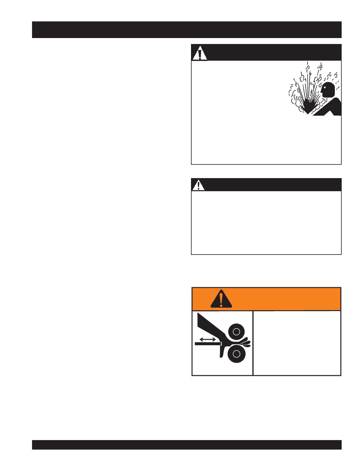
Avoid pinch points or crush points that can be created
by the load or parts of the cylinder. Do not wear loose
jewelry when operating the rebar bender.
Moving parts can
crush and cut.
WARNING
keep hands
clear of rollers while
rebar bender is
operating.
ALWAYS
JIMMY SERIES HYDRAULIC REBAR BENDERS — OPERATION AND PARTS MANUAL — REV. #9 (01/04/08) — PAGE 8
POWER UNIT TRANSPORTING (Electric-Hydraulic Pump)
When transporting of the power unit (pump) is required,
ALWAYS carry unit by its handle.
ALWAYS wrap power and remote cable cords neatly to
avoid tripping and damage when transporting.
MAINTENANCE
NEVER lubricate components or attempt service on a
operational rebar bender.
ALWAYS maintain rebar bender in correct operating
condition.
ALWAYS fix damage to the rebar bender immediately
and always replace broken parts. Replace with only MQ
recommended parts.
EMERGENCIES
ALWAYS know the location of the nearest
fire
extinguisher
and first aid kit.
In emergencies
always
know the location of the
nearest phone or
keep a phone on the job site
.
Also know the phone numbers of the nearest
ambulance
,
doctor
and
fire department
. This
information will be invaluable in the case of an
emergency.
JIMMY SERIES HYDRAULIC REBAR BENDERS — RULES FOR SAFE OPERATION
ELECTRICAL SAFETY
ALWAYS test the
ON/OFF
switch on the hydraulic power
unit before operating. The purpose of this switch is to shut
down the rebar bender.
NEVER use a extension cord that is frayed or damaged
where the insulation has been cut.
NEVER carry the hydraulic power unit by its power cord
or disconnect it by yanking the cord from the power outlet.
ALWAYS make certain that the proper extension cord
has been selected for the job. See Table 5.
NEVER allow power cord to
lay in wate
r.
NEVER
stand in water
while operating the rebar bender.
When connecting the hydraulic power unit to a power
receptacle, make sure the receptacle circuit is connected
to either a GFCI receptacle or a receptacle protected by
a 20 amp circuit breaker.
When plugging the hydraulic power unit into a power
receptacle, check the nameplate for the correct operating
voltage. Operating the rebar bender at the wrong voltage
will damage the electrical components. ALWAYS read
the nameplate before applying power.
This hydraulic power unit is equipped with a 3-prong male
power plug. DO NOT use a 2-prong adapter when plugging
into a wall outlet. This will defeat the purpose of the ground
circuit. If the plug does not fit into the receptacle, contact
a qualified electrician to install a 3-conductor wall
receptacle (outlet).
Avoid body contact with grounded surfaces such as pipes,
radiators, ranges and refrigerators. There is an increased
risk of electrical shock if your body is grounded.
DO NOT expose the hydraulic power unit to rain or wet
conditions. Water entering the power unit will increase
the risk of electrical shock.
When operating the hydraulic power unit outside, be sure
to use the appropriate outdoor extension cord. This type
of extension cord reduces the risk of electrical shock.
ALWAYS remove the AC power cord from the power
source before performing any service or maintenance on
the rebar bender. This preventative safety measure
reduces the possibility of accidental starting.
JIMMY SERIES HYDRAULIC REBAR BENDERS — OPERATION AND PARTS MANUAL — REV. #9 (01/04/08) — PAGE 9
trahCeziSrabeR.2elbaT
ledoM5315BJ5317BJ0905BJ0907BJ0908BJ0819BJ09011BJ
suidaRgnidneB
°535300008081
)31#/M01(4#
★★
)61#/M51(5#
★★★★
)91#/M02(6#
★★★★★★★★★
)22#/AN(7#
★★★★★★★★★
)52#/M52(8#
★★★★★★
)92#/M03(9#
★★★
)23#/AN(01#
)63#/M53(11#
* Minimum bend measured from bottom of machine to top of angle.
** American Concrete Institute (ACI) has approved the wheel used in this device as the proper radius for bending the bar size indicated; Concrete Reinforcing Steel
Institute(CRSI) requirements are met for the bar size indicated.
snoitacificepSredneBrabeR.1elbaT
ledoM5315BJ5317BJ0905BJ0907BJ0908BJ0819BJ09011BJ
elgnAgnidneB
°53530000809
yticapaCrabeR
)eziSraB(
5#,4#7#,6#6#,5#,4#8#,7#,6#9#,8#,7#,6#01#,9#,8#,7#11#,01#,9#,8#
dneBmuminiM
*)mc(.ni
)7.21(5)7.21(5)7.21(5)3.02(8)3.02(8)9.72(11)6.53(41
nosehcnignicapSraBmuminiM
retnec
22333 5.35.3
dneB;rebmuNraBdevorppA-ICA
**suidaR
°531;5531;709;509;709;8081;909;11#
)gk(.blthgieW
)01(22)21(62)21(62)62(85)92(26)54(001)05(011
)gk(.blthgieWgnippihS
)51(43)12(74)81(93)33(47)04(98)45(911)26(631
)mc(.nisnoisnemiDllarevO
5.3x11x32
)9.8x9.72x4.85(
3x9x91
)6.7x9.22x3.84(
5.4x9x71
)4.11x9.22x2.34(
5.5x5.21x5.12
)41x8.13x6.45(
5.5x41x72
)41x6.53x6.86(
6x71x91
)2.51x2.34x3.84(
6x91x72
)2.51x3.84x6.86(
)mc(.nisnoisnemiDgnippihS
42x31x03
)16x33x67(
42x31x03
)16x33x67(
42x31x03
)16x33x67(
51x31x42
)83x33x16(
51x31x42
)83x33x16(
51x31x42
)83x33x16(
51x31x42
)83x33x16(
snoitacilppA
dneBdradnatS°09
✓✓✓✓✓✓✓
kooHenaC°081
sdneBtesffO
✓✓✓✓✓✓✓
gninethgiartS
✓✓✓✓✓✓✓
kooHeiTdnapurritScimsieS
✓✓
Rebar Size:
Standard 1/8 inch increments
(Metric Hard/Soft
Conversion)
Example:
#8 Rebar ÷ 8 = 1-inch
#4 Rebar ÷ 8 = 4/8 = 1/2-inch
NOTE
★★★
ACI/CRSI Approved for this size
★★
Acceptable bend radius for ACI/CRSI requirements
Capable of bending rebar but does not meet ACICRSI requirements
Not capable of bending this size rebar
JIMMY SERIES HYDRAULIC REBAR BENDERS SPECIFICATIONS (REBAR UNIT)
JIMMY SERIES HYDRAULIC REBAR BENDERS — OPERATION AND PARTS MANUAL — REV. #9 (01/04/08) — PAGE 10
JIMMY SERIES HYDRAULIC REBAR BENDERS SPECIFICATIONS (PUMP)
snoitacificepSpmuPciluardyHcirtcelE.3elbaT
pmuP
ledoM1UPJ
noitacificepSrotoMT1051WEP
epyTpmuPcirtcelE
rotoM)wk11.1(PH5.1
deepSMPR5271
egatloVtupnIzH06@511
tnerruCspmA2.61
leveLdnuoSABd08
yticapaCliO)sretill87.3(lag1
gnitaRerusserP)aPk159,86(isp000,01
erusserPegatStsriF)aPk628,4(
isp007
daoLoN@etaRwolFni514
3
mc008,6(nim/
3
)nim/
isp000,01@etaRwolFni16
3
mc000,1(nim/
3
)nim/
elbaClortnoCetomeR)sretem75.4(.tf51
evlaVlortnoCnoitisoP-3yaW-3launaM
thgieWteN).gk7.23(.sbl2.97
thgie
WssorG).gk1.74(.sbl401
)HxWxL(noisnemiDnotraC
.ni8/1-12x8/1-11x8/5-61
).mc56.35x52.82x22.24(
)HxWxL(noisnemiDetarC
.ni8/7-22x8/5-11x2/1-71
).mc01.85x25.92x54.44(
JIMMY SERIES HYDRAULIC REBAR BENDERS — OPERATION AND PARTS MANUAL — REV. #9 (01/04/08) — PAGE 11
JIMMY SERIES HYDRAULIC REBAR BENDERS — GENERAL INFORMATION
GENERAL INFORMATION
The
MQ Jimmy Series Hydraulic Rebar Benders
are designed
to be used as
portable
on-site rebar benders, capable of bending
in-place rebar to approved American Concrete Institute (ACI) radius.
Labor time and injuries are greatly reduced from manually bending
rebar. Bends of 90°, 135° or 180° can now be completed in seconds
at the correct elevation after forms are stripped away.
With seven models to choose from, the Jimmy Series rebar benders
can accommodate a wide variety of rebar angles and sizes. Please
reference Tables 1 and 2 in this manual for the rebar bender that
best fits your application.
REBAR BENDING APPLICATIONS (Figures 1 thru 4)
Pilings
Caissons
Bridge and Decking
Retrofits
Columns
Straightening
Walls
Rebar Columns
90° rebar (Figure 1) at top of column can be bent after forms
have been removed
Bending after concrete is poured allows you to stock bottom
beam bars, eliminating the need to thread bottom beam bars.
Rebar at top of column can be bent at exactly the correct
elevation allowing top beam bars to placed on top of 90°
bend.
Figure 1. Columns
Rebar Straightening
Rebar can be straightened using JB5090, JB7090, JB8090,
JB9180 and JB11090.
NEVER straighten rebar that is bent greater than 30°. Check
with building codes before straightening rebar
Figure 2. Rebar Straightening
Before the rebar can be straightened by the JB5090, JB7090
or JB8090, it will be necessary to replace the main roller with
the straightening roller. The straightening roller is included
with each of the above models from the factory. To accomplish
this task remove the main shaft as outlined in Figure 14.
Some agencies may not permit the straightening of rebar
for existing bends of more than 30°. DO NOT attempt to
straighten rebar bends greater than 30°.
CAUTION
CAUTIONCAUTION
CAUTIONCAUTION
CAUTION
JIMMY SERIES HYDRAULIC REBAR BENDERS — OPERATION AND PARTS MANUAL — REV. #9 (01/04/08) — PAGE 12
JIMMY SERIES HYDRAULIC REBAR BENDERS — GENERAL INFORMATION
Rebar Spirals and Cages
Can bend rebar up to 135° (Figure 3) and fits between spirals
as close as 2 in. (5 cm. ) on center.
No welding required.
Figure 3. Rebar Spirals and Cages
Rebar Walls
No welding required
Bends hooks in rebar after forms have been removed.
Bends graduated bars to precise elevations.
Reduces size and number of holes and splices required in
forms.
Figure 4. Rebar Walls
Electric-Hydraulic Pump
All Jimmy Series Hydraulic Rebar Benders require an electric-
powered hydraulic pump to supply the necessary pressure to actuate
the hydraulic cylinder. This hydraulic pump consists of a drive
cylinder, oil reservoir and electronics for either remote or manual
operation.
The electric motor for this pump is a 1.5 HP motor. Each electric
motor requires 115 VAC, 60 Hz input for normal operation. Amperage
draw for the electric motor at 10,0000 psi (68,951 kpa) is
approximately 13 amps. Reference Figure 5 for oil volume versus
pressure.
The hydraulic pump is equipped with a 3-way, 3- position manual
operated valve. This valve allows the operator to remotely control
the
advance
,
hold
and
return
functions of the rebar bender. A 15 ft.
(4.57 meters) remote control cable allows the operator to control the
pump remotely.
Figure 5. Oil Volume vs Pressure
Model PEW1501T Electric/Hydraulic Pump
0
50
100
150
200
250
300
350
400
450
0 1000 2000 3000 4000 5000 6000 7000 8000 9000 10000
Pressure (psi)
Oil Volume (cu.in/min)
JIMMY SERIES HYDRAULIC REBAR BENDERS — OPERATION AND PARTS MANUAL — REV. #9 (01/04/08) — PAGE 13
1. Remote Control Unit – Allows the hydraulic cylinder
on the rebar unit to be
advanced
or
held
.
2. Remote Control Cable – Allows the Electric-Hydraulic
Pump to be operated remotely.
3. Hydraulic Reservoir– Holds 1.00 gallon (3.78 liters)
of hydraulic oil. Fill only with recommended type
hydraulic oil.
4. Pump Control Lever – Move this lever to actuate the
hydraulic cylinder on the rebar bender. The lever allows
the cylinder to be
advanced
,
held
or
returned.
5. Hydraulic Oil Fill Cap – Remove this cap to add
hydraulic fluid to the reservoir. Fill with commercial
hydraulic oil.
6. Electric-Hydraulic Pump/Carrying Handle – When
transporting of the pump is required, always use the
carrying handle or lifting bale to lift the unit.
7. Electric-Hydraulic Pump ON/OFF Switch – Move the
toggle switch to the forward position to activate the
electric motor. The electric motor will stay on as long
as the switch is held. Release the switch to turn off the
electric motor.
8. AC Power Cord – Plug this 10 ft. (3.0 meters) power
cord into a 115 VAC grounded type receptacle. NEVER
remove the ground pin from the plug. This will defeat
the ground circuit and greatly increase the possibility
of electrical shock.
9. Female Quick Disconnect Fitting – Connects to the
hydraulic hose and allows for easy removal.
10. Hydraulic Hose (Rebar Bender) – Connect one end
of this hose to the female quick disconnect fitting on
the electric-hydraulic pump, connect the other end (90°
fitting) to the hydraulic input port on the rebar bender
cylinder.
11. Hose Cap – When the rebar bender is not in use,
ALWAYS cover the hose’s male fitting with this cap.
This will prevent dirt and foreign matter from entering
the cylinder cavity.
12. Main and Upper Arm Rollers – Always keep large
and small rollers clean and lubricated to insure smooth
rolling. Remove any dirt or debris that may have
accumulated on the rollers during operation.
13. Hydraulic Cylinder – When actuated can apply a force
between 2~10 tons (2,032 ~10,160 kg.)
14. Rebar Adjustment Bolt – There is an adjustment bolt
on the side plate of the rebar bender. Adjust these bolts
to accommodate different size rebar.
15. Main Roller Shaft – To remove the large roller (main)
or stuck rebar from the unit, push the roller shaft inward
to release. Some units have a pin-clip mechanism for
the removal of the main roller. See Figure 14.
16. Electric Motor On/Off Switch – When placed in the
ON position, supplies 115VAC, 60Hz power to the
electric motor.
17. Straightening Roller – Accessory roller for
straightening rebar. For use with JB5090, JB7090,
JB8090 only.
Figure 6. Jimmy Hydraulic Rebar Bender Components
JIMMY SERIES HYDRAULIC REBAR BENDERS — COMPONENTS
JIMMY SERIES HYDRAULIC REBAR BENDERS — OPERATION AND PARTS MANUAL — REV. #9 (01/04/08) — PAGE 14
JIMMY SERIES HYDRAULIC REBAR BENDERS — INSPECTION
BEFORE STARTING
CAUTION - Read Manual
Before attempting to operate
this rebar bender, and to avoid
serious injury to personnel,
always read and understand
operation manual. Failure to
read and understand operation
manual could result in serious
harm or even death!
DANGER - Flammable/Combustible Materials
NEVER operate the rebar bender or
hydraulic pump in or around flammable
materials. The possibility exists of the rebar
bender emitting a spark during operation. If
contact is made between the sparks and the
flammable material, the result could be fire
or explosion causing damage to the equipment and severe
bodily harm even death!
INSPECTION
Before each use, visually inspect the items listed below.
Regular maintenance and visual checks of the rebar bender
and power unit prior to operation will minimize repairs and
help ensure normal operation of the bender and electric-
hydraulic pump.
Check for wear and damage to rollers, pin, nuts and bolts,
clip, side plates and hydraulic arm. Clean, lubricate and
replace as required.
Rebar bender can
ONLY
be used with a standard
hydraulic pump rated at 10,000 PSI. Refer to the pump’s
manual for operation and maintenance instructions.
Check the hydraulic pump fluid level.
Check that all hydraulic connections are clean.
Check all hydraulic hoses for cuts, holes, or excessive
wear.
Inspect all fittings and couplers, make sure they are clean
and fitted with dust caps.
Check that couplings to pump and bender are tightened
securely.
Check for a cracked or damaged cylinder or rebar bender
Check for excessive wear, bending, damage, or
insufficient thread engagement.
Check for leaking hydraulic fluid
Check for a scored or damaged piston rod.
Improperly functioning or damaged components
Check for loose bolts.
Check for damaged or improperly assembled accessory
equipment.
Check for modified, welded, or altered equipment.
Check for bent or damaged couplers or port threads.
JIMMY SERIES HYDRAULIC REBAR BENDERS — OPERATION AND PARTS MANUAL — REV. #9 (01/04/08) — PAGE 15
JIMMY SERIES HYDRAULIC REBAR BENDERS — APPLYING POWER
CONNECTING THE POWER
1. The electric-hydraulic pump requires 115 VAC, 60 Hz
power. Applying power to the pump that is not speci-
fied will cause severe damage to the pump's electric
motor. Always read the
electrical data plate
before
applying power to the pump.
2. The power plug on the pump is a 3-prong grounded type
plug. ALWAYS connect this plug to a 3-prong grounded
receptacle. NEVER plug this device into a 2-prong type
receptacle. This will defeat the ground circuit. The use of
a 3-prong to 2-prong adapter is strictly prohibited.
3. Connect the pump's AC power cord to a 115 VAC wall
receptacle or portable generator (Figure 7) that is pro-
tected by a 20 amp circuit breaker. For best results
connect the power cord to a GFCI receptacle.
POWER
CORD
(POWER ON)
WET
HANDS
During operation of this rebar bender, there
exists the possibility of
electrocution,
electrical shock or burn,
which can cause
severe bodily harm
or even
DEATH!
To avoid these hazards:
NEVER use damaged or worn cables when plugging the
rebar bender into an AC power receptacle.
NEVER grab or touch a live power
cord with wet hands.
NEVER stand in water and touch a
live power cord.
DANGER - ELECTROCUTION HAZARDS
Since
distance
can affect
voltage
drop
when using an extension cord,
ALWAYS make certain that the
proper extension cord has been se-
lected for the job. See Table 4.
NOTE
Figure 7. Connecting The Power
4. Connect the hand-held remote control cable to the power
input receptacle on the power unit
5. To apply power to the electric-hydraulic pump, place the
ON/OFF toggle switch (Figure 7) to the ON position (up).
)noitarepOesahPelgniS,zH06(noitceleSelbaC.4elbaT
nitnerruC
serepmA
nIdaoL
sttaW
htgneLelbaCelbawollAmumixaM
021tA
stloV
eriW01#eriW21#eriW41#eriW61#
5.2003.tf0001.tf006.tf573.tf052
5006.tf005.tf003.tf002.tf521
5.7009.tf053.tf002.tf521.tf001
010021.tf052.tf051.tf001
510081.tf
051.tf001.tf56
020042.tf521.tf57.tf05
.egatlovwolmorftlusernacegamadtnempiuqE:NOITUAC
JIMMY SERIES HYDRAULIC REBAR BENDERS — OPERATION AND PARTS MANUAL — REV. #9 (01/04/08) — PAGE 16
OPERATION
Control Valve Lever
1. This hydraulic pump has a 3-way, 3-position valve that
is activated by a control valve lever (Figure 8). In the
neutral
position, PORT A is CLOSED, meaning there
is no flow of pressurized fluid.
2. In the
forward (extend)
position, “PORT A” is OPEN,
meaning the flow of pressurized fluid is allowed (Figure
9) and the hydraulic cylinder will extend once the remote
control toggle switch is pressed.
JIMMY SERIES HYDRAULIC REBAR BENDERS — OPERATION
Figure 8. Control Valve Lever (Neutral Position)
Figure 9. Control Valve Lever (Forward Position)
Remote Control Unit
1. On the remote control unit there is a toggle switch.
When pressed, this toggle switch (Figure 11) will
activate (extend) the hydraulic cylinder. Releasing
the toggle switch will hold the cylinder in place.
Figure 11. Remote Control Unit
Positioning the Rebar Bender (Method 1)
For Models JB5090, JB7090, JB8090, JB9180, JB11090
1. Place the pump control valve lever
(Figure 8) in the
neutral
position.
2. Place the rebar bender over the rebar between the main
roller and upper roller arm at the desired elevation of the
bend as shown in Figure 12. Use vise-grips to hold the
rebar bender base in place.
3. Rotate the rebar bender until the hydraulic cylinder is in
the opposite direction of the desired bend.
3. In the
reverse
(retract)
position, “PORT A” returns
hydraulic fluid back into tank (Figure 10) and the hydrau-
lic cylinder retracts.
Figure 10. Control Valve Lever (Reverse Position)
NOTE
The Remote Control Unit does not
retract the hydraulic cylinder. The
retraction of the cylinder must be
done manually (Power Unit).
Make certain the area is clear of bystanders before starting
the bending process.
CAUTION
CAUTIONCAUTION
CAUTIONCAUTION
CAUTION
NOTE
The cylinder on the JB5135 and
JB7135 models retract when the
control valve lever is in the forward
position and extend when the lever is
in the reverse position. See Figure 15.
JIMMY SERIES HYDRAULIC REBAR BENDERS — OPERATION AND PARTS MANUAL — REV. #9 (01/04/08) — PAGE 17
JIMMY SERIES HYDRAULIC REBAR BENDERS — OPERATION
Figure 12. Rebar Placement
4. Place the pump control valve lever in the
forward
position (Figure 9).
5. Place and hold the toggle switch on the remote control
unit in the ON position. The rebar bending process should
begin.
6. When the desired rebar bend angle (Figure 13) has been
achieved, release the toggle switch on the remote
control unit. This will stop the forward motion of the
cylinder.
7. To retract the cylinder, place the pump control valve
lever in the
reverse
/retract position. The cylinder will
retract with or without the pump running.
8. To remove the rebar bender, place the pump control
valve lever in the
neutral position
and either lift the
bender over the end of the rebar or remove the main roller
and shaft (Figure 14) and slide the rebar bender off the
rebar.
Figure 13. 9 Rebar Bend
3. Next, remove the
main roller
and place the rebar bender
over the rebar. Use vise-grips to hold the rebar bender
base in place.
3a. When bending rebar with models JB5090, JB7090,
JB8090 only: exchange the main roller for the straight-
ening roller supplied from the factory.
4. Reinsert the main roller, making sure the rebar is positioned
between the main roller and the upper roller arm.
5. Operate rebar bender as outlined in Method 1, steps 3 thru 8.
Figure 14. Removing the Main Roller Shaft
Positioning the Rebar Bender (Method 2)
For Models JB5090, JB7090, JB8090, JB9180, JB11090
1. Place the pump control valve lever
(Figure 8) in the
neutral
position.
2. Remove the Main Roller Shaft as shown in Figure 14.
Apply a suitable amount of pressure to the shaft to
either insert or remove it. It is held in place by a detent
ball plunger
Use ONLY graded rebar. Ungraded rebar may break and
cause serious injury!
WARNING
NOTE
The JB5090, JB7090 and JB8090
bender may require adjustment in
order to obtain a 90° bend. See
Rebar Adjustment Bolt section.
JIMMY SERIES HYDRAULIC REBAR BENDERS — OPERATION AND PARTS MANUAL — REV. #9 (01/04/08) — PAGE 18
Positioning the Rebar Bender (Method 3)
For Model JB5135
1. Place the pump control valve lever
(Figure 8) in the
neutral
position.
2. Send the end of the spiral rebar through the gap in the puller
hook. Secure the puller hook around the straight rebar and
align the puller rollers on the spiral rebar (Figure 15).
3. Place the pump control valve lever in the
forward
position.
4. Place and hold the toggle switch on the remote control
unit (ON position). The rebar bending process should
begin.
5. Activating the rebar bender will then cause the puller
hook and cylinder to retract and curl the end of the spiral
rebar up to 135° around the straight rebar.
6. When the desired angle has been achieved, release the
toggle switch on the remote control unit. This will stop the
retraction of the puller hook and cylinder.
7. To extend the puller hook and cylinder, place the pump
control valve lever in the
reverse
/retract position.
8. To remove the rebar bender, place the pump control
valve
lever in the
neutral
position
and lift the bender over the
end of the rebar.
Figure 15. JB5135 Rebar Placement — Rebar Bending
JIMMY SERIES HYDRAULIC REBAR BENDERS — OPERATION
Positioning the Rebar Bender (Method 4)
For Model JB7135
1. Place the pump control valve lever
(Figure 8) in the
neutral
position.
2. Send the end of the spiral rebar through the gap between
the puller hook and main roller. Rotate the main roller so
that the main roller groove is in the 1 o’clock position.
Secure the straight rebar in the main roller groove. Align
the puller rollers on the spiral rebar (Figure 16).
3. Operate rebar bender as outlined in Method 3, steps 3 thru 8.
Figure 16. JB7135 Rebar Placement — Rebar Bending
JIMMY SERIES HYDRAULIC REBAR BENDERS — OPERATION AND PARTS MANUAL — REV. #9 (01/04/08) — PAGE 19
JIMMY SERIES HYDRAULIC REBAR BENDERS — OPERATION/SHUT-DOWN
Shutting Down the Rebar Bender and Power Unit
1. Remove Rebar Bender from the rebar.
2. Place ON/OFF toggle switch in the OFF position.
3. Unplug AC Power cord from receptacle.
4. Disconnect hydraulic hose from Power Unit.
5. Place protective hose cap on the male coupler end of
the hose.
6. Roll up hydraulic hose. Store Rebar Bender in a safe
place.
7. On the Power Unit, wrap the power and remote cords
neatly. Store Power Unit in safe place.
Rebar Adjustment Bolt
For Model JB5090, JB7090, JB8090
The rebar bender may require adjustment in order to obtain a
90° bend. Adjustment is necessary due to inconsistencies in the
rebar produced by steel mills and because each bender is
capable of handling multiple diameters of rebar.
1. Use a 19 MM socket to loosen the bolt and a 24 MM
socket to loosen the locknut (Figure 17) until the adjust-
able block can be slid easily in the crescent groove on
the side of the rebar. Note: there is no need to remove the
hardware.
2. Insert a piece of the rebar to be used into the machine
to assist in positioning the adjustable stop.
3. Slide the adjustable stop towards the rebar (away from
the hydraulic ram) until it makes contact with the rod.
4. Back the adjustable stop off the rebar slightly so the rod
can pass easily through the machine without binding.
5. Tighten the hardware securely , connect the bender to
the pump and make a test bend. You should now be able
to attain the desired bending angle. If the desired bend is
not attained, repeat the process until the desired result
is achieved.
Figure 17. Rebar Adjustment Bolt
JIMMY SERIES HYDRAULIC REBAR BENDERS — OPERATION AND PARTS MANUAL — REV. #9 (01/04/08) — PAGE 20
PREVENTIVE MAINTENANCE
Preventive maintenance should be performed on a daily or
weekly basis depending on the amount and working use. A
higher than normal operating pressure could indicate a need
for immediate maintenance.
A clean well lubricated rebar bender will operate faster and
smoother and will allow for more accurate readings from
pump pressure gauges.
PUMP MAINTENANCE (Cleaning and Lubrication)
1. Remove the side plates on the rebar bender to expose
moving parts. Clean all moving parts with a clean rag
and solvent.
2. Check the cylinder on all models for leaks.
3. Lubricate all moving parts with
high pressure grease
.
4. For rebar bender models with cables (Models JB11090
and JB9180), lubricate the five grease fittings daily or
after approximately 50 rebar bend operations. Check
hydraulic cables daily for fraying.
4. For rebar models JB135 and JB7135, visually check for
dents or cracks in the side plates. Replace plates
immediately if damaged. Clean and lubricate both rollers
to insure smooth rotation.
5. Check hydraulic oil every 40 hours of operation. Add
hydraulic oil if necessary. Oil can be added by removing
the vent cap. Use a funnel.
ADDING HYDRAULIC OIL
1. Make sure electric motor is OFF.
2. Depressurize system by placing pump control lever in
the
neutral
position. Disconnect hydraulic hose from
port A of system.
3. Remove
vent cap
on top plate of reservoir. Visually
inspect to see if oil level is low. Oil level should be about
2 inches (50 mm) from top of reservoir plate.
4. Using a funnel, add oil to about 2 inches (50 mm) from
top of reservoir plate.
JIMMY SERIES HYDRAULIC REBAR BENDERS — MAINTENANCE
STORAGE
When the rebar bender and electric hydraulic pump are not
used, please store in a clean dry location out of the reach of
children and away from unauthorized personnel.
Be sure that all dust caps are attached to their respective
hoses and the hand-held remote control cable and pump
power cord are neatly wrapped.
CHANGING HYDRAULIC OIL
1. Change hydraulic oil
once a year
.
2. Remove drain plug, tilt the pump, then pour used fluid
into a sealable container.
3. Dispose the hydraulic fluid in accordance with local
regulations.
4. Install drain cap.
5. Remove vent cap and fill with recommended type
hydraulic oil.
NOTE
Completely change hydraulic oil
every
300 hours
of operation.
Change the oil more frequently when
pump is used in an extremely dusty
environment or when the oil has
been overheated.
NOTE
Use only good quality hydraulic oil.
Multiquip recommends Mobil DTE
15M or equivalent. NEVER use
brake fluid, transmission fluid,
turbine oil, motor oil alcohol glycerin
etc. Use of other than the
recommended hydraulic oil will void warranty and damage the
pump and hydraulic hose used in the rebar bending application.
  • Page 1 1
  • Page 2 2
  • Page 3 3
  • Page 4 4
  • Page 5 5
  • Page 6 6
  • Page 7 7
  • Page 8 8
  • Page 9 9
  • Page 10 10
  • Page 11 11
  • Page 12 12
  • Page 13 13
  • Page 14 14
  • Page 15 15
  • Page 16 16
  • Page 17 17
  • Page 18 18
  • Page 19 19
  • Page 20 20
  • Page 21 21
  • Page 22 22
  • Page 23 23
  • Page 24 24
  • Page 25 25
  • Page 26 26
  • Page 27 27
  • Page 28 28
  • Page 29 29
  • Page 30 30
  • Page 31 31
  • Page 32 32
  • Page 33 33
  • Page 34 34
  • Page 35 35
  • Page 36 36
  • Page 37 37
  • Page 38 38
  • Page 39 39
  • Page 40 40
  • Page 41 41
  • Page 42 42
  • Page 43 43
  • Page 44 44
  • Page 45 45
  • Page 46 46

MQ Multiquip JB11090 User manual

Category
Water pumps
Type
User manual

Ask a question and I''ll find the answer in the document

Finding information in a document is now easier with AI