Page is loading ...

IN1404XT
Video Scaler and Switcher
68-755-01
Rev. B
12 04

This symbol is intended to alert the user of important operating and maintenance
(servicing) instructions in the literature provided with the equipment.
This symbol is intended to alert the user of the presence of uninsulated dangerous
voltage within the product's enclosure that may present a risk of electric shock.
Caution
Read Instructions • Read and understand all safety and operating instructions before using the
equipment.
Retain Instructions • The safety instructions should be kept for future reference.
Follow Warnings • Follow all warnings and instructions marked on the equipment or in the user
information.
Avoid Attachments • Do not use tools or attachments that are not recommended by the equipment
manufacturer because they may be hazardous.
Warning
Power sources • This equipment should be operated only from the power source indicated on the
product. This equipment is intended to be used with a main power system with a grounded
(neutral) conductor. The third (grounding) pin is a safety feature, do not attempt to bypass or
disable it.
Power disconnection • To remove power from the equipment safely, remove all power cords from
the rear of the equipment, or the desktop power module (if detachable), or from the power
source receptacle (wall plug).
Power cord protection • Power cords should be routed so that they are not likely to be stepped on or
pinched by items placed upon or against them.
Servicing • Refer all servicing to qualified service personnel. There are no user-serviceable parts
inside. To prevent the risk of shock, do not attempt to service this equipment yourself because
opening or removing covers may expose you to dangerous voltage or other hazards.
Slots and openings • If the equipment has slots or holes in the enclosure, these are provided to
prevent overheating of sensitive components inside. These openings must never be blocked by
other objects.
Lithium battery • There is a danger of explosion if battery is incorrectly replaced. Replace it only
with the same or equivalent type recommended by the manufacturer. Dispose of used batteries
according to the manufacturer's instructions.
Ce symbole sert à avertir l’utilisateur que la documentation fournie avec le matériel
contient des instructions importantes concernant l’exploitation et la maintenance
(réparation).
Ce symbole sert à avertir l’utilisateur de la présence dans le boîtier de l’appareil de
tensions dangereuses non isolées posant des risques d’électrocution.
Attention
Lire les instructions• Prendre connaissance de toutes les consignes de sécurité et d’exploitation avant
d’utiliser le matériel.
Conserver les instructions• Ranger les consignes de sécurité afin de pouvoir les consulter à l’avenir.
Respecter les avertissements • Observer tous les avertissements et consignes marqués sur le matériel ou
présentés dans la documentation utilisateur.
Eviter les pièces de fixation • Ne pas utiliser de pièces de fixation ni d’outils non recommandés par le
fabricant du matériel car cela risquerait de poser certains dangers.
Avertissement
Alimentations• Ne faire fonctionner ce matériel qu’avec la source d’alimentation indiquée sur
l’appareil. Ce matériel doit être utilisé avec une alimentation principale comportant un fil de
terre (neutre). Le troisième contact (de mise à la terre) constitue un dispositif de sécurité :
n’essayez pas de la contourner ni de la désactiver.
Déconnexion de l’alimentation• Pour mettre le matériel hors tension sans danger, déconnectez tous
les cordons d’alimentation de l’arrière de l’appareil ou du module d’alimentation de bureau (s’il
est amovible) ou encore de la prise secteur.
Protection du cordon d’alimentation • Acheminer les cordons d’alimentation de manière à ce que
personne ne risque de marcher dessus et à ce qu’ils ne soient pas écrasés ou pincés par des
objets.
Réparation-maintenance • Faire exécuter toutes les interventions de réparation-maintenance par un
technicien qualifié. Aucun des éléments internes ne peut être réparé par l’utilisateur. Afin
d’éviter tout danger d’électrocution, l’utilisateur ne doit pas essayer de procéder lui-même à ces
opérations car l’ouverture ou le retrait des couvercles risquent de l’exposer à de hautes tensions
et autres dangers.
Fentes et orifices • Si le boîtier de l’appareil comporte des fentes ou des orifices, ceux-ci servent à
empêcher les composants internes sensibles de surchauffer. Ces ouvertures ne doivent jamais
être bloquées par des objets.
Lithium Batterie • Il a danger d'explosion s'll y a remplacment incorrect de la batterie. Remplacer
uniquement avec une batterie du meme type ou d'un ype equivalent recommande par le
constructeur. Mettre au reut les batteries usagees conformement aux instructions du fabricant.
Safety Instructions • English
Consignes de Sécurité • Français
Sicherheitsanleitungen • Deutsch
Dieses Symbol soll dem Benutzer in der im Lieferumfang enthaltenen
Dokumentation besonders wichtige Hinweise zur Bedienung und Wartung
(Instandhaltung) geben.
Dieses Symbol soll den Benutzer darauf aufmerksam machen, daß im Inneren des
Gehäuses dieses Produktes gefährliche Spannungen, die nicht isoliert sind und
die einen elektrischen Schock verursachen können, herrschen.
Achtung
Lesen der Anleitungen • Bevor Sie das Gerät zum ersten Mal verwenden, sollten Sie alle Sicherheits-und
Bedienungsanleitungen genau durchlesen und verstehen.
Aufbewahren der Anleitungen • Die Hinweise zur elektrischen Sicherheit des Produktes sollten Sie
aufbewahren, damit Sie im Bedarfsfall darauf zurückgreifen können.
Befolgen der Warnhinweise • Befolgen Sie alle Warnhinweise und Anleitungen auf dem Gerät oder in
der Benutzerdokumentation.
Keine Zusatzgeräte • Verwenden Sie keine Werkzeuge oder Zusatzgeräte, die nicht ausdrücklich vom
Hersteller empfohlen wurden, da diese eine Gefahrenquelle darstellen können.
Vorsicht
Stromquellen • Dieses Gerät sollte nur über die auf dem Produkt angegebene Stromquelle betrieben
werden. Dieses Gerät wurde für eine Verwendung mit einer Hauptstromleitung mit einem
geerdeten (neutralen) Leiter konzipiert. Der dritte Kontakt ist für einen Erdanschluß, und stellt
eine Sicherheitsfunktion dar. Diese sollte nicht umgangen oder außer Betrieb gesetzt werden.
Stromunterbrechung • Um das Gerät auf sichere Weise vom Netz zu trennen, sollten Sie alle
Netzkabel aus der Rückseite des Gerätes, aus der externen Stomversorgung (falls dies möglich
ist) oder aus der Wandsteckdose ziehen.
Schutz des Netzkabels • Netzkabel sollten stets so verlegt werden, daß sie nicht im Weg liegen und
niemand darauf treten kann oder Objekte darauf- oder unmittelbar dagegengestellt werden
können.
Wartung • Alle Wartungsmaßnahmen sollten nur von qualifiziertem Servicepersonal durchgeführt
werden. Die internen Komponenten des Gerätes sind wartungsfrei. Zur Vermeidung eines
elektrischen Schocks versuchen Sie in keinem Fall, dieses Gerät selbst öffnen, da beim Entfernen
der Abdeckungen die Gefahr eines elektrischen Schlags und/oder andere Gefahren bestehen.
Schlitze und Öffnungen • Wenn das Gerät Schlitze oder Löcher im Gehäuse aufweist, dienen diese
zur Vermeidung einer Überhitzung der empfindlichen Teile im Inneren. Diese Öffnungen dürfen
niemals von anderen Objekten blockiert werden.
Litium-Batterie • Explosionsgefahr, falls die Batterie nicht richtig ersetzt wird. Ersetzen Sie
verbrauchte Batterien nur durch den gleichen oder einen vergleichbaren Batterietyp, der auch
vom Hersteller empfohlen wird. Entsorgen Sie verbrauchte Batterien bitte gemäß den
Herstelleranweisungen.
Este símbolo se utiliza para advertir al usuario sobre instrucciones importantes de
operación y mantenimiento (o cambio de partes) que se desean destacar en el
contenido de la documentación suministrada con los equipos.
Este símbolo se utiliza para advertir al usuario sobre la presencia de elementos con
voltaje peligroso sin protección aislante, que puedan encontrarse dentro de la caja
o alojamiento del producto, y que puedan representar riesgo de electrocución.
Precaucion
Leer las instrucciones • Leer y analizar todas las instrucciones de operación y seguridad, antes de usar
el equipo.
Conservar las instrucciones • Conservar las instrucciones de seguridad para futura consulta.
Obedecer las advertencias • Todas las advertencias e instrucciones marcadas en el equipo o en la
documentación del usuario, deben ser obedecidas.
Evitar el uso de accesorios • No usar herramientas o accesorios que no sean especificamente
recomendados por el fabricante, ya que podrian implicar riesgos.
Advertencia
Alimentación eléctrica • Este equipo debe conectarse únicamente a la fuente/tipo de alimentación
eléctrica indicada en el mismo. La alimentación eléctrica de este equipo debe provenir de un
sistema de distribución general con conductor neutro a tierra. La tercera pata (puesta a tierra) es
una medida de seguridad, no puentearia ni eliminaria.
Desconexión de alimentación eléctrica • Para desconectar con seguridad la acometida de
alimentación eléctrica al equipo, desenchufar todos los cables de alimentación en el panel trasero
del equipo, o desenchufar el módulo de alimentación (si fuera independiente), o desenchufar el
cable del receptáculo de la pared.
Protección del cables de alimentación • Los cables de alimentación eléctrica se deben instalar en
lugares donde no sean pisados ni apretados por objetos que se puedan apoyar sobre ellos.
Reparaciones/mantenimiento • Solicitar siempre los servicios técnicos de personal calificado. En el
interior no hay partes a las que el usuario deba acceder. Para evitar riesgo de electrocución, no
intentar personalmente la reparación/mantenimiento de este equipo, ya que al abrir o extraer las
tapas puede quedar expuesto a voltajes peligrosos u otros riesgos.
Ranuras y aberturas • Si el equipo posee ranuras o orificios en su caja/alojamiento, es para evitar el
sobrecalientamiento de componentes internos sensibles. Estas aberturas nunca se deben obstruir
con otros objetos.
Batería de litio • Existe riesgo de explosión si esta batería se coloca en la posición incorrecta. Cambiar
esta batería únicamente con el mismo tipo (o su equivalente) recomendado por el fabricante.
Desachar las baterías usadas siguiendo las instrucciones del fabricante.
Instrucciones de seguridad • Español
Precautions

i
IN1404XT Video Scaler and Switcher • Table of Contents
Table of Contents
Chapter 1 • Introduction ....................................................................................................... 1-1
About this Manual ............................................................................................................. 1-2
About the Scaler.................................................................................................................. 1-2
TP transmission .................................................................................................................. 1-3
TP cable advantages ........................................................................................................... 1-3
Features ................................................................................................................................... 1-4
Chapter 2 • Installation.......................................................................................................... 2-1
Installation Overview ....................................................................................................... 2-2
Mounting the Scaler .......................................................................................................... 2-2
Rack mounting ................................................................................................................... 2-2
Cabling and Rear Panel Views ...................................................................................... 2-3
Input connections .............................................................................................................. 2-3
Standard output connections ............................................................................................ 2-4
TP video output connections............................................................................................. 2-4
Termination of TP cable...................................................................................................... 2-5
Cable testing ....................................................................................................................... 2-5
Equalizing pair skew ........................................................................................................... 2-6
RS-232 connection ............................................................................................................. 2-7
Power connection .............................................................................................................. 2-7
Configuration ....................................................................................................................... 2-7
Chapter 3 • Operation ............................................................................................................. 3-1
Front Panel Controls and Indicators .......................................................................... 3-2
Video controls .................................................................................................................... 3-2
Audio controls .................................................................................................................... 3-3
Menu control buttons........................................................................................................ 3-3
Front Panel Operations .................................................................................................... 3-4
Power ................................................................................................................................. 3-4
Menu operation ................................................................................................................. 3-4
Status indicators .................................................................................................................. 3-5
Menu system ...................................................................................................................... 3-6
Video menu ......................................................................................................................... 3-6
Brightness screen ...................................................................................................... 3-6
Contrast screen ......................................................................................................... 3-6
RGB Gain screen ........................................................................................................ 3-8
Color Saturation screen ............................................................................................ 3-8
Hue screen ................................................................................................................. 3-8
Sharpness screen ....................................................................................................... 3-8
Gamma screen........................................................................................................... 3-9
Noise Filter screen ..................................................................................................... 3-9
Comb/Trap selection screen ...................................................................................... 3-9
Reset Video screen .................................................................................................... 3-9

ii IN1404XT Video Scaler and Switcher • Table of Contents
Table of Contents, cont’d
Audio menu.........................................................................................................................3-9
Bass screen ................................................................................................................. 3-9
Treble screen ........................................................................................................... 3-10
Balance screen ......................................................................................................... 3-10
Reset Audio screen ................................................................................................. 3-10
Input menu ........................................................................................................................
3-11
Signal Format screen .............................................................................................. 3-12
Aspect Ratio screen ................................................................................................. 3-12
Auto Switching screen ............................................................................................ 3-13
Input Labels screen ................................................................................................. 3-14
Horizontal Tracking screen ..................................................................................... 3-14
Phase screen ............................................................................................................ 3-14
Advanced screen ..................................................................................................... 3-14
Reset Input screen ................................................................................................... 3-15
Output menu.....................................................................................................................
3-15
Resolution screen .................................................................................................... 3-15
Refresh Rate screen ................................................................................................ 3-16
Seamless Mode screen ............................................................................................ 3-16
Size screen ............................................................................................................... 3-17
Position screen ........................................................................................................ 3-17
Sync Format screen ................................................................................................. 3-17
Blue Screen screen .................................................................................................. 3-18
Reset Output screen ............................................................................................... 3-18
Advanced menu ................................................................................................................
3-18
Factory Reset screen ............................................................................................... 3-18
User Memory screen ............................................................................................... 3-18
Baud Rate screen .................................................................................................... 3-19
Delimitors screen .................................................................................................... 3-19
Reset RS-232 screen ................................................................................................ 3-19
System Information screen ..................................................................................... 3-20
Enabling seamless switching ........................................................................................... 3-20
Setting up seamless switching..........................................................................................3-20
Seamless switching operation ..........................................................................................3-20
Power-up shortcuts .......................................................................................................... 3-21
Optimizing the Video...................................................................................................... 3-21
Setting up a DVD source ................................................................................................. 3-21
Resolution and refresh rates ........................................................................................... 3-22
CRT displays — selecting the optimum resolution..........................................................3-22
CRT displays — selecting the optimum refresh rate .......................................................3-22
Fixed pixel displays — selecting the optimum resolution and refresh rate ..................3-23
Advanced Input submenu options .................................................................................. 3-24
Input blanking adjustment...............................................................................................3-25
Active area adjustment ....................................................................................................3-26
Total pixels adjustment.....................................................................................................3-28
Scan Type screen ...............................................................................................................3-28
Input Mode screen ............................................................................................................3-29
Optimizing the Audio ..................................................................................................... 3-29

iii
IN1404XT Video Scaler and Switcher • Table of Contents
Troubleshooting ................................................................................................................ 3-30
General checks ................................................................................................................. 3-30
Specific problems ............................................................................................................. 3-31
Chapter 4 • Programmer’s Guide..................................................................................... 4-1
Communications Protocols ............................................................................................ 4-2
Serial Control Cable Wiring ........................................................................................... 4-2
Host-to-Scaler Instructions............................................................................................. 4-2
Command code structure .................................................................................................. 4-3
Scaler Responses ................................................................................................................. 4-3
Using the Command/Response Table ........................................................................ 4-3
Symbols............................................................................................................................... 4-4
Command/Response Table for RS-232 Commands ............................................. 4-5
Appendix A • Reference Information...........................................................................B-1
Specifications........................................................................................................................B-2
Part Numbers ........................................................................................................................ B-4
Included parts ....................................................................................................................B-4
Optional accessories .......................................................................................................... B-4
Cables .................................................................................................................................B-4
VGA cables.......................................................................................................................... B-4
Pre-cut cables ..................................................................................................................... B-5
Bulk cable ........................................................................................................................... B-6
Assorted connectors, cables, and adapters ...................................................................... B-7

iv IN1404XT Video Scaler and Switcher • Table of Contents
Table of Contents, cont’d
68-755-01
Rev. B
12 04
All trademarks mentioned in this manual are the properties of their respective owners.

IN1404XT Video Scaler and Switcher
1
Chapter One
Introduction
About this Manual
About the Scaler
Features

Introduction, cont’d
IN1404XT Video Scaler and Switcher • Introduction1-2
Introduction
About this Manual
This manual contains installation, configuration, and operating information for the
Extron IN1404XT video scaler and switcher (referred to in this manual as the
“scaler”).
• Chapter 1 identifies the scaler’s features.
• Chapter 2 details how to install the scaler.
• Chapter 3 describes how to operate the scaler and use all of its features.
• Chapter 4 provides information about programming and operating the scaler
under RS-232 control, such as from a PC or host controller.
• Appendix A lists the scaler’s specifications and pertinent part numbers.
About the Scaler
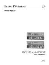
The Extron IN1404XT is a video scaler that incorporates a four-input video and
stereo audio switcher (figure 1-1). The scaler accepts NTSC/PAL/SECAM/NTSC
4.43 S-video (Y/C) and composite video inputs and stereo audio inputs on all four
inputs and high resolution RGB video and interlaced or progressive component
(YUV) video on inputs 3 and 4. The IN1404XT scales the inputs to standard VGA
and HDTV resolutions and refresh rates and outputs RGBHV, RGBS, or RGsB
video and stereo audio. Input 4 can also be set to a passive mode that provides no
decoding, scaling or change of refresh rate and can be set as a timing reference for
seamless switching. The scaler can seamlessly switch to and from passive input 4
to bring professionalism and style to boardrooms or other system integration
environments. Seamless switching allows switching between sources without a
loss of sync. The scalers’ scaling capabilities permit differing video formats on each
input to be displayed by a common projector.
Each video input is individually configurable to allow for different video formats.
The scaler allows analog RGBHV, RGBS, and RGsB video, component video,
S-video, and composite video signals to be displayed on a device with a fixed
resolution and aspect ratio, such as an liquid crystal display (LCD) projector, digital
light processor (DLP) projector, or plasma display.
The scaler inputs high-resolution RGBHV/RGBS/RGsB video, and component
video on two sets of five BNC connectors. The scaler inputs S-video on 4-pin mini
DIN connectors (inputs 1 and 2) and on two sets of two BNC connectors (inputs 3
and 4). The scaler inputs four composite video inputs on BNC connectors. The
scaler inputs audio on RCA connectors.
The IN1404XT scales the input up to any of 48 output resolutions and rates and
outputs the scaled video, as two identical RGBHV, RGBS, or RGsB video outputs,
on five BNCs and a 15HD connector. Additionally, the scaler acts as a twisted pair
(TP) transmitter, outputting the identical video signal on an RJ-45 connector for
connection to an optional Extron VTR001CM TP receiver. (See TP transmission, in
this chapter, for more information about the RJ-45 output.) With all three video
outputs active at all times, the IN1404XT can drive three video displays
simultaneously, with no need for a distribution amplifier.
There is one stereo audio output, on left and right RCA connectors.
For upscaling, the IN1404XT converts the horizontal and vertical sync timing and
the number of lines of the lower-resolution video input to match the native
resolution of the display. This produces an undistorted, brighter picture.
The scaler is housed in a rack-mountable, 1U high, 17.5” wide metal enclosure.
With the included mounting ears, the scaler is rack-mountable. The scaler has an
internal 100VAC to 240VAC, 50/60 Hz, 25 watts auto-switchable power supply that
provides worldwide power compatibility.

1-3IN1404XT Video Scaler and Switcher • Introduction
Extron
VTR001
Twisted Pair Receiver
Extron
IN1404XT
Video/RGB Scaler
Extron
CPM101
Connector Plate
VCR/DVD
Video Camera
Laptop
Laptop
Projector
Extron
Skew-Free
UTP Cable
(up to 500')
V
ID
E
O
I
N
P
U
T
VTT001CM
Twisted Pair Receiver
P
O
W
ER
VTT001CM
Twisted Pair Receiver
VIDEO OUTPUT
V
T
R
0
01
C
M
T
w
is
ted P
a
ir
R
e
ce
iv
er
POWER
Figure 1-1— Typical IN1404XT Video Scaler and Switcher application
TP transmission
The TP output on the RJ-45 connector and an optional Extron VTR001CM receiver
provide a system for long-distance distribution of computer (RGBHV or RGBS)
video over Extron’s skew-free A/V UTP cable or over CAT 5 unshielded twisted
pair (UTP), shielded twisted pair (STP), or foil shielded twisted pair (FTP) cable.
The VTR001CM can receive RGsB signals from the scaler. However, the red,
green, and blue video signals’ black levels are not clamped to a 0V reference, as
for RGBHV or RGBS. For most displays, this is not a problem. On some
displays (such as some LCD displays) however, the black levels of the red,
green, and blue signals may change as the average picture level changes,
resulting in an unacceptable image.
TP cable advantages
Extron’s skew-free cable or CAT 5 cable is a fraction of the size of coaxial cable, as
well as being much lighter, more flexible, and far less expensive. These TP
products make cable runs simpler and less cumbersome. Termination of the cable
with RJ-45 connectors is simple, quick, and economical.

Introduction, cont’d
IN1404XT Video Scaler and Switcher • Introduction1-4
Features
Inputs —
Video inputs — The scaler switches among two fully-configurable RGB, HDTV
component video, interlaced component video, progressive scan video,
S-video, or composite video inputs on 5 BNC connectors (inputs 3 and 4); two
S-video inputs on 4-pin mini-DIN connectors (S-video inputs 1 and 2 only);
or composite video inputs on single BNC connectors (composite video inputs
1 and 2).
Either S-video or composite video, but not both, can be connected to input 1
and to input 2. The two inputs can each be a different video format, but only
one format can be connected to an input.
Audio inputs — The scaler switches among four unbalanced stereo audio inputs
on RCA connectors. Inputs can come from sources such as a VCR, DVD
player, computer audio card, or other audio device that outputs a stereo line-
level signal.
Outputs —
Standard video outputs — The IN1404XT outputs scaled video signals as
progressive RGBHV, RGBS, or RGsB, from 640 x 480 up to 1365 x 1024, to
match the optimum or native resolution of virtually any display device, on
five BNC connectors and a 15-pin HD connector.
The output refresh rate is selectable as desired. When used with LCD or DLA
displays, Extron recommends the 60 Hz setting. Higher output refresh rates
can be used with CRT displays to reduce flicker.
TP video output — The scaler outputs a third video signal encoded into a set of
proprietary analog signals on an RJ-45 connector. The scaler transmits this
output in the same format as Extron’s VTT001CM TP transmitter. An
optional Extron VTR001CM receiver can receive this set of signals and
convert them to a high resolution RGBHV, RGBS, or RGsB output (identical
to the 5-BNC and 15-pin HD output).
Audio outputs — The scaler provides an unbalanced line level signal that is
identical to the input signal. This output can drive any line level compatible
audio unit, or a local device such as powered speakers.
Video output resolutions —
The IN1404XT outputs an image scaled up to the following output resolutions:
• 640 x 480 (VGA) at 60 Hz, 72 Hz, 75 Hz, 85Hz, 96 Hz, 100Hz, and 120 Hz
•
800 x 600 (SVGA) at 60 Hz, 72 Hz, 75 Hz, 85Hz, 96 Hz, 100Hz, and 120 Hz
• 852 x 480 at 60 Hz, 72 Hz, 75 Hz, 85Hz, 96 Hz, 100Hz, and 120 Hz
• 1152 x 864 at 60 Hz, 72 Hz, 75 Hz, and 85Hz
• 1024 x 768 (XGA) at 60 Hz, 72 Hz, 75 Hz, and 85Hz
• 1280 x 720 (HDTV - 720p) at 60 Hz, 72 Hz, 75 Hz, 85Hz, 96 Hz, and 100 Hz
• 1280 x 768 at 56 Hz, 60 Hz, and 65 Hz
• 1280 x 1024 (SXGA) at 60 Hz, 72 Hz, and 75 Hz
• 1365x 768 (wide XGA) at 60 Hz, 72 Hz, 75 Hz, and 85 Hz
• 1365 x 1024 (plasma) at 60 Hz
Advanced motion compensation — Extron’s video processing techniques,
advanced motion prediction and compensation methods treat motion content

1-5IN1404XT Video Scaler and Switcher • Introduction
and still content with different algorithms to yield high fidelity images that are
free of visible scan lines.
Inverse 3:2 pulldown detection for NTSC for film-originated video material —
This advanced film mode processing feature helps maximize image detail
and sharpness for video sources that originated from film. When film is
converted to NTSC video, the film frame rate has to be matched to the video
frame rate in a process called 3:2 pulldown. Jaggies and other image artifacts
can result if conventional deinterlacing techniques are used on film-source
video. The IN1404XT’s advanced film mode processing recognizes signals
that originated from film. The scaler then applies video processing
algorithms that optimize the conversion of video that was made with the 3:2
pulldown process. This results in richly detailed images with sharply
defined lines.
Quad-standard decoding — The IN1404XT’s video decoder provides accurate
video decoding of composite video and S-video in the NTSC, PAL, SECAM,
and NTSC 4.43 standards. The advanced 3-line adaptive comb filter that
decodes composite video reduces cross-color interference and hanging dots
while maintaining maximum image bandwidth and detail.
Seamless Switching - Input 4, when configured as a passive (unscaled) input,
serves as a time reference for seamless switching. The IN1404XT provides a
seamless transition between scaled inputs on 1, 2, or 3 (RGB, component,
S-video, or composite video) and the passive RGB video on input 4.
Picture controls — A wide variety of picture controls are available for fine picture
adjustments:
• Position
• Size
• Aspect ratio
• Hue
• Saturation
• Brightness and contrast
• Gamma
• Horizontal tracking
• Sharpness
Once these adjustments are made, the settings are stored in non-volatile
memory and automatically recalled when the same input source is selected
again.
Advanced image adjustment controls — A wide variety of picture controls are
available to optimize the image when the scaler is used with proprietary and
non-standard input signals.
Once these adjustments are made, the settings are stored in non-volatile
memory and automatically recalled when the same input source is selected
again.
Blue screen mode — The scaler can be set to output a blue video field, to help
installers calibrate the monitor or projector. Blue screen is always available,
whether or not an input is present or properly adjusted.
On screen menus - The scaler puts its menu displays on the output video stream,
for display by the output monitors or projectors. The menu system provides
easy control of video adjustments including hue, color, contrast, brightness,

Introduction, cont’d
IN1404XT Video Scaler and Switcher • Introduction1-6
gamma, sharpness, image size, image position, and edge blanking.
Individual image settings can be optimized and stored for each input. Each
time an input is selected, all image settings stored for that input are
automatically recalled. The on-screen menus also make it easy to verify and
adjust advanced settings such as output signal resolution, refresh rate, sync
format; the RS-232 control options; and the reset to factory defaults function.
A handy System Info menu option uses the on-screen display to show
comprehensive information about the input and output signals and scaler
settings.
Audio follow and breakaway — Audio switching can follow its corresponding
video input signal or, under RS-232 control, audio can be broken away from
the video input.
Except as noted in Video breakaway, below, when a new input channel is
selected, the audio automatically switches to the newly selected input
channel.
Video breakaway — Under RS-232 control, video can be switched without
disturbing the audio switch.
Operational flexibility — Operations such as input and scaling selection, picture
controls, and saving and recalling of presets can be performed on the front
panel or over the RS-232 link. The RS-232 links allow remote control via a PC
or control system.
• Front panel control — The scaler’s front panel controller and on-screen
menus support individual input selection, resolution selection, volume
control, and complete configuration of the scaler.
• ASCII character command set — The remote control protocol uses Extron’s
ASCII character command set for easy programming and operation.
Freeze mode — Provides a high quality still image for applications that require
close examination of a specific video frame. Freeze mode operates for video
and RGB signals that are processed by the scaling circuitry. Passive
(unscaled) video on input 4 cannot be frozen.
Blank mode — Suppresses the output video image. Blank silences the R, G, and B
video outputs but the scaler still outputs sync. This ensures that the output
device does not lose sync lock. Blank mode operates for video and RGB
signals that are processed by the scaling circuitry. Passive (unscaled) video
on input 4 cannot be blanked.
User memories — The IN1404XT provides 128 user memories that store all video,
audio, and input parameters. User memories allow the unit to be optimized
for a large number of sources and gives the capability to recall those settings
quickly. The memories make it easier to add to the number of inputs to the
scaler by putting a switcher in front of an input.
Rack mountable — The 1U high scaler can be mounted in any conventional 19”
wide rack using the included IN9123B rack ears.
Power — The 100VAC to 240VAC, auto-switchable, internal power supply of the
IN1404XT provides worldwide power compatibility.

IN1404XT Video Scaler and Switcher
2
Chapter Two
Installation
Installation Overview
Mounting the Scaler
Cabling and Rear Panel Views
Configuration

Installation, cont’d
IN1404XT Video Scaler and Switcher • Installation2-2
Installation
Installation Overview
To install and set up an IN1404XT video scaler and switcher for operation, perform
the following steps:
1
Disconnect power from all of the equipment, including the video and audio
source(s), and the devices that will receive the output video and audio signals.
Ensure the power switch on the scaler is off.
2
Rack mount the scaler if desired. See Mounting the Scaler in this chapter.
3
Connect the video and audio input cables. See Input connections in this
chapter.
4
Connect the standard video and audio output cables. See Standard output
connections in this chapter.
5
If desired, connect the TP cable between the scaler and an optional VTR001CM
TP receiver and connect the output cables from the TP receiver to the display.
See TP output connection in this chapter and refer to the VTT001CM and
VTR001CM - Twisted Pair Transmitter and Receiver manual, part # 68-760-01.
6
If desired, connect the RS-232 cable. See RS-232 connection in this chapter.
7
Connect the AC power cable. See Power connection in this chapter. Turn on
the sources, video and audio destinations, and the scaler.
6
Configure the scaler’s inputs and configure the output for the optimum
image. See chapter 3, Operation and chapter 4, Programmer’s Guide.
Mounting the Scaler
The scaler includes four installed rubber feet. If you are going to rack mount the
scaler, mount it before cabling it (see Rack mounting, below). The IN1404XT is
exactly 1U high without the rubber feet; if you plan to rack mount the scaler with
other equipment directly underneath it, the feet must be removed.
Rack mounting
Rack mount the scaler as follows:
1. Remove the three enclosure screws on one side of the scaler (figure 2-1).
Rack-mount
Bracket
Figure 2-1 — Mounting the scaler
n
ns

2-3IN1404XT Video Scaler and Switcher • Installation
2. Attach one rack mount bracket to that side of the scaler with three screws
removed in step 1.
3. Repeat steps 1 and 2 on the other side of the scaler.
4. Insert the scaler into the rack, align the holes in the mounting bracket
with those of the rack.
5. Secure the scaler to the rack with machine screws.
Cabling and Rear Panel Views
All connectors are on the rear panel (figure 2-2).
UTP Link
1 10111
89
2 2 63
3
4 4
4
75
Figure 2-2 — IN1404XT rear panel connectors and power switch
With the exception of input 1 and 2 S-video, all video input and output
connections to the scaler are made with female BNC
connectors. Some types of video output devices do
not have BNC video output connectors. For these
cases, a suitable cable or connector adapter is
necessary between the device output connector and
the BNC input connector of the switcher. The
Extron part number for the RCA-to-BNC adapter
is 10-264-01.
Input connections
1
Input 1 and Input 2 S-video connectors — Connect S-video sources to these
4-pin mini DIN connectors. If necessary, use an 8” Extron SVHS - BNC
adapter, part #26-353-01.
— Or —
2
Input 1 and Input 2 composite video connectors — Connect composite video
sources to these female BNC connectors.
For input 1 and input 2, video can be connected to either the S-video
input or the composite video input, but not both. If you connect to
both, the scaler will not accept either signal.
3
Input 3 and Input 4 connectors — Connect computer or RGB video,
component video, S-video, or composite video to these female BNC
connectors. Figure 2-3 shows how to connect the various video formats.
4
Input 1 through Input 4 audio connectors — Connect each unbalanced stereo
audio input to these pairs (left and right) of RCA connectors. Computer
sound cards and other devices with a 3.5 mm mini output connector can be
connected using an optional Extron IN9107 3.5 mm stereo mini male to (2)
RCA male cable.
BNC ConnectorRCA Connector
RCA-to-BNC Connector

Installation, cont’d
IN1404XT Video Scaler and Switcher • Installation2-4
Cr
R
RGBHV
RGBS
RGsB,
Component
Y
G/Gs
Cb
BH/S V
S-video
Composite
video
Cr
R
Y
G/Gs
Cb
B H/S V
(Pr)
R
Y
G/Gs
(Pb)
Cr Y Cb
(R-y) Y (B-Y)
B H/S V
Cr
(C)
R
Y
G/Gs
Cb
B H/S V
Cr
R
Y
(Vid)
G/Gs
Cb
B H/S V
Figure 2-3 — Connections for various input video formats
The audio bass, treble, and balance levels for each input can be individually
set via the front panel or the RS-232 link. See chapter 3, Operation, and
chapter 4, Programmer’s Guide for details.
Standard output connections
The two standard outputs, consisting of five BNC connectors and a 15HD
connector, output the identical video signal and the same sync format.
5
Output BNC connectors— Connect an RGBHV, RGBS, or RGsB video display
to these female BNC connectors. Figure 2-4 shows how to connect the various
video formats.
V
RGBHV
H/S
R
G/Gs
B
V
RGBS
H/S
R
G/Gs
B
V
RGsB
H/S
R
G/Gs
B
Figure 2-4 — BNC output connections for RGBHV and RGBS video
6
Output 15HD connector — Connect an RGBHV, RGBS, or RGsB video
display to this female 15HD connector.
The two standard output connectors, BNCs and 15-pin HD, are individually
buffered (even when input 4 is configured as passive (unscaled). They can
both be simultaneously connected and transmitted up to 100 feet on high
quality coax cable without degradation of either output.
7
Output audio connectors— Connect an audio device, such as an amplifier or
powered speakers, to these left and right RCA connectors.
By default, the audio output follows the video switch. Audio breakaway,
commanded via the RS-232 link, allows you to select from any one of the
audio input sources. See chapter 3, Operation and chapter 4, Programmer’s
Guide for details.
TP video output connection
RJ-45 termination must comply with the TIA/EIA T 568A or TIA/EIA T 568B
wiring standards for all connections.

2-5IN1404XT Video Scaler and Switcher • Installation
8
RGB video transmission connector — Connect one end of a TP cable to this
RJ-45 female connector. Connect the other end of the TP cable to an optional
Extron VTR001CM or other compatible Extron TP receiver. See Optional
Accessories, in Appendix A, Reference Information, for compatible TP receivers.
The VTR001CM can receive RGBHV and RGSB signals from the scaler with
no loss of image quality. The VTR001 CM can also receive RGsB signals from
the scaler. However, the red, green, and blue video signals’ black levels are not
clamped to a 0V reference, as for RGBHV or RGBS. For most displays, this is
not a problem. On some displays (such as some LCD displays) however, the
black levels of the red, green, and blue signals may change as the average
picture level changes, resulting in an unacceptable image.
Termination of TP cable
Figure 2-5 details the recommended termination of TP cables in accordance with
the TIA/EIA T 568A and TIA/EIA T 568 B wiring standards. You can use either
standard, but ensure you use the same standard on both ends of the cable.
Clip DownSide
1
1&2
3&6 4&5
7&8
2345678
12345678
Pin
Wire color
RGB video signal
1
White-green
Red/V. sync+
2 Green
Red/V. sync-
3
White-orange
Power
4
Blue Green+
5
White-blue
Green-
6
Orange
Power
7 White-brown Blue/H. sync+
8
Brown
Blue/H. sync-
RJ-45 connector
Twisted Pairs
Wire color
TIA/EIA T-568-A
TIA/EIA T-568-B
White-orange
Orange
White-green
Blue
White-blue
Green
White-brown
Brown
Figure 2-5 — TP cable termination
Cable testing
To ensure proper cable termination, each transmission cable system that uses CAT 5
cable should be tested (Extron’s skew-free UTP cable does not need to be tested).
Testing the cable from the RJ-45 connections at the transmitter and receiver gives
the most accurate indications of cable problems.
There are two varieties of cable runs: simple runs, in which a single cable is
terminated only at the transmitter and receiver, and complex runs, which can
include patch bays and multiple terminations and lengths of cable. In either case,
the entire cabling system should be tested.
A complete test measures cable length and tests the wire map, attenuation, NEXT,
PSNEXT, ELFEXT, PSELFEXT, return loss, ACR and PSACR. All of these tests are
critical for digital data transfer, but not for analog video. While all of these tests are
important indicators of the quality of the cable termination, the most critical testing
parameters for video transfer are wire map (T-568-A or B termination) and pair
length measurements. The largest concern is equalization of skew between cable
pairs. Cable systems of 300 feet or less should exhibit no transmission problems if
they pass at least CAT 5 channel certification testing.

Installation, cont’d
IN1404XT Video Scaler and Switcher • Installation2-6
The Microtest OMNI SCANNER 2 performs comprehensive certification testing to
the proposed CAT 6 standards. Other manufacturers also make testing equipment.
The tests include advanced diagnostics for troubleshooting the cause and location
of many cable and termination problems. For simple installation testing, the
Microtest MICRO SCANNER PRO tests wire map and cable length, including
individual cable pair length.
Equalizing pair skew
The manufacturing process for network (CAT 5) UTP cable leads to a condition
called pair skew. For best results, pair skew needs to be equalized when using the
CAT 5 cable in A/V applications. The design of Extron’s skew-free A/V UTP cable
minimizes pair skew to the point that equalization is not required.
Skew exists between pairs when the physical length of one wire pair is different
from another. As the transmission cable length increases, the amount of skew
increases. Skew affects the displayed image when the differential length between
wire pairs exceeds 2 feet, causing the timing of the red, green, and blue video
signals to appear out of alignment (horizontal registration errors). A white vertical
line on a black field can appear as individual red, green, and blue lines that are
close together; the signal transmitted on the shortest wire pair leads the other colors
and appears to the left on the display.
UTP cable test equipment measures and reports wire pair length. The report on the
various pair lengths can be used in equalizing pair skew. The nominal velocity of
propagation (NVP — the speed at which the signal travels on the transmission line,
measured as a percentage of the speed of light) of TP cable is very close to that of
conventional coaxial cable. The similarity in NVP means that:
• by using an Extron IN9045-L6 15HD male-to-5 BNC male, 6’ cable, to adapt
the output on a 15HD connector to BNC connectors,
• and then adding an additional length of coax equal to the length of pair skew,
placed on the receiver’s output,
you can equalize the effects of pair skew (figure 2-6).
If UTP cable test measurement cannot be done, pair skew can still be equalized by
viewing a test pattern with a critical eye. Examine the test pattern for loss of
horizontal registration and, through a process of trial and error, equalize any pair
skew with coax extensions on the red, green, and/or blue outputs.
Extron skew compensation coax cables are available in lengths of 2 through 20 feet,
see Appendix A, Reference Information, for part numbers.

2-7IN1404XT Video Scaler and Switcher • Installation
Extron
IN1404XT
Video/RGB Scaler
Pair RGB video
1, 2
Red
7, 8
Green
4, 5
Blue
Projector
VIDEO IN
PU
T
VTT001CM
Twisted Pair Receiver
Extron CPM101
Connector Panel
CAT 5 UTP Cable
... THEN insert a 15HD-to-BNC
extension cable and a four-foot
skew compensation cable to
equalize UTP skew for red video.
IF cable measurement
indicates that the pair
with wires
1 and 2
is
four feet shorter than
the other signals...
Extron
VTR001
Twisted Pair Receiver
Figure 2-6 — Pair skew equalization
RS-232 connection
9
RS-232 port — Connect a host device, such as a computer, RS-232 capable
PDA, or third-part control system, to the scaler via this 3.5 mm, 3-pole captive
screw connector for serial RS-232 control (figure 2-7).
FunctionPin
TX
Gnd
RX
Transmit data
Signal ground
Receive data
Figure 2-7 — RS232 port pin assignments
See chapter 4, Programmer’s Guide, for definitions of the ASCII command set.
Power connection
10
AC power connector — Plug a standard IEC power cord between this
connector and a 100 to 240VAC, 50 Hz or 60 Hz power source.
11
Power switch — Turn the power switch on. The front panel LEDs flash twice
during power-up and then all but the LED for the previously selected input
go out.
Configuration
The IN1404XT can be configured using either the front panel controls or the ASCII
command set. See chapter 3, Operation and chapter 4, Programmer’s Guide.

Installation, cont’d
IN1404XT Video Scaler and Switcher • Installation2-8
/