Page is loading ...

User’s Guide
Extron Electronics, USA
1230 South Lewis Street
Anaheim, CA 92805
USA
714.491.1500
Fax 714.491.1517
Extron Electronics, Europe
Beeldschermweg 6C
3821 AH Amersfoort
The Netherlands
+31.33.453.4040
Fax +31.33.453.4050
Extron Electronics, Asia
135 Joo Seng Road, #04-01
PM Industrial Building
Singapore 368363
+65.6383.4400
Fax +65.6383.4664
Extron Electronics, Japan
Kyodo Building
16 Ichibancho
Chiyoda-ku, Tokyo 102-0082 Japan
+81.3.3511.7655
Fax +81.3.3511.7656
www.extron.com
© 2006 Extron Electronics. All rights reserved.
Sync
Input type ..................................... RGBHV, RGBS, RGsB, RsGsBs
Output type .................................. RGBHV, RGBS, RGsB, RsGsBs
Input level ..................................... 3 V to 5 Vp-p
Output level .................................. TTL: 5 Vp-p, unterminated
Input impedance .......................... 510 ohms
Output impedance ....................... 50 ohms
Max. propagation delay ............. 60 ns
Max. rise/fall time ....................... 4 ns
Polarity .......................................... Positive or negative
General
External power supply ............... 100 VAC to 240 VAC, 50/60 Hz, 4.5 watts,
external, autoswitchable;
to 9 VDC, 1 A, regulated
Power input requirements ......... 9 VDC, 0.2 A
Temperature/humidity .............. Storage: -40 to +158 °F (-40 to +70 °C) /
10% to 90%, noncondensing
Operating: +32 to +122 °F (0 to +50 °C) /
10% to 90%, noncondensing
Rack mount ................................... No
Enclosure type .............................. Plastic
Enclosure dimensions ................. 1.4" H x 5.0" W x 3.3" D
3.6 cm H x 12.7 cm W x 8.4 cm D
(Depth excludes connectors.)
Product weight ............................. 1.6 lbs (0.7 kg)
Shipping weight .......................... 3 lbs (2 kg)
Vibration ....................................... ISTA 1A in carton (International Safe
Transit Association)
Listings .......................................... UL, CUL
Compliances ................................. CE
MTBF ............................................. 30,000 hours
Warranty ....................................... 3 years parts and labor
All nominal levels are at ±10%.
Specifications are subject to change without notice.
Distribution Amplifier
P/2 DA2 Plus
68-362-01 Rev. D
01 06

P/2 DA2 Plus • Installation and OperationP/2 DA2 Plus • Installation and Operation
Installation
32
Specifications
Video
Gain ............................................... Unity
Bandwidth .................................... 270 MHz (-3 dB), fully loaded
Video input
Number/signal type ................... 1 VGA-UXGA RGBHV, RGBS, RGsB,
RsGsBs
Connectors .................................... (1) 15-pin HD male cable (built-in)
Nominal level ............................... 0.7 Vp-p for RGB
Minimum/maximum levels ...... Analog: 0.4 V to 1.4 Vp-p with no offset at
unity gain
Impedance .................................... 75 ohms
Horizontal frequency .................. 15 kHz to 135 kHz
Vertical frequency ....................... 30 Hz to 170 Hz
Return loss .................................... <-38.3 dB @ 5 MHz
Video output
Number/signal type ................... 2 VGA-XGA RGBHV, RGBS, RGsB,
RsGsBs
Connectors .................................... (2) 15-pin HD female
Nominal level ............................... 0.7 Vp-p for RGB
Minimum/maximum levels ...... 0.4 V to 1.4 Vp-p
Impedance .................................... 75 ohms
Return loss .................................... -41 dB @ 5 MHz
DC offset ....................................... ±5 mV maximum with input at 0 offset
Description
The P/2 DA2 Plus is a one input, two output distribution
amplifier that accepts video input from a VGA-UXGA compatible
PC and distributes that signal to separately buffered outputs.
Each output can be extended with Extron MHR cables up to 250'
in length.
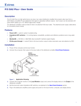
An example of a typical installation is shown in the following
diagram.
Installation
1. Power off the computer and its local monitor.
2. Connect the computer’s VGA output to the input cable of
the distribution amplifier.
PC
Extron
P/2 DA2 Plus
Projector
Up to 250' w/ Extron
VGA Extension Cable
3. Connect the computer’s monitor to the “Local Monitor”
output of the distribution amplifier.
P/2 DA2 Plus
4. Connect an LCD panel, a VGA-UXGA monitor, or a
projector to the other output.
5. Connect power to the distribution amplifier.
6. Power on the local monitor, the computer, and display
device.
Operation
After the distribution amplifier and its connected devices are
powered up, the system is fully operational. If any problems are
encountered, verify that the cables are routed and connected
properly.
Cables
Description Part number
M6' MHR cable — 6' (1.8 m) 26-238-01
M15' MHR cable — 15' (4.5 m) 26-238-02
M50' MHR cable — 50' (15.2 m) 26-238-18
M75' MHR cable — 75' (22.8 m) 26-238-19
M100' MHR cable — 100' (30.4 m) 26-238-20
SY VGAM-RGBHVM — 6' (1.8 m) 26-533-02
SY VGAM-RGBHVM — 25' (7.6 m) 26-533-04
SY VGAM-RGBHVM — 50' (15.2 m) 26-533-06
SY VGAM-RGBHVM — 100' (30.4 m) 26-533-07
/


