Sauder 414723 Installation guide
- Category
- Storage chests & cabinets & trunks
- Type
- Installation guide

PLEASE CONTACT US
BEFORE RETURNING
YOUR UNIT TO THE STORE
1-800-523-3987
www.sauder.com
Made in the USA
Archbold, OH
NOTE: THIS INSTRUCTION BOOKLET CONTAINS
IMPORTANT SAFETY INFORMATION.
PLEASE READ AND KEEP FOR FUTURE REFERENCE.
English .................... Page 1-22
Français ...............Pages 23-25
Espanol .............Páginas 26-28
Lot #: 356340 09 / 19 / 13
Date Purchased: ____________________
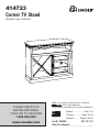
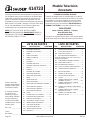
414723
Corner TV Stand
Barrister Lane Collection

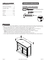
ASSEMBLY TOOLS REQUIRED
Hammer
No. 2 Phillips Screwdriver
Tip Shown Actual Size
ADULT ASSEMBLY REQUIRED
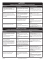
Use of a TV that is too heavy or large is hazardous. A TV that is too heavy will create a risk of a tip-over that can cause severe injury
or death. A TV that is too large for the available space might be accidentally pushed or bumped off the furniture, or subject to tip-over.
• Check the size and weight of your TV. Compare it to the diagram below – before you begin assembly!
• This Sauder unit is designed for use with televisions weighing less than 50 pounds. Never use with a TV that weighs more.
• The size of the television, front-to-back and side-to-side, must fi t within the space defi ned in the diagram.
• Never place the front edge of the TV past the front edge of the TV support shelf (or stop molding – if equipped)
• Never allow the sides of the TV to extend past the side edges of the TV support surface.
• If the TV has a CRT picture tube, the picture tube cone may extend past the rear of the support shelf.
• Be sure to apply the warning label as instructed in the last assembly step. The label provides important safety related information.
WARNING
TABLE OF CONTENTS
Part Identifi cation .......................3
Hardware Identifi cation .............4
Assembly Steps ....................5-22
Français ..............................23-25
Espanol ...............................26-28
Safety .................................29-30
Warranty ...................................31
19-1/8"
43-1/8"
50 lbs.
Page 2 www.sauder.com/services 414723

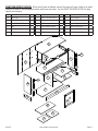
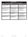
PART IDENTIFICATION: While not all parts are labeled, some of the parts will have a label or an inked
letter on the edge to help distinguish similar parts from each other. Use this PART IDENTIFICATION to help
identify similar parts.
A RIGHT END 1
B LEFT END 1
C UPRIGHT 1
D SMALL UPRIGHT 1
E TOP 1
F BOTTOM 1
G SHELF 1
H CROSS SHELF 1
I SMALL CROSS SHELF 2
J BACK 1
K DOOR 1
L ADJUSTABLE SHELF 2
M RIGHT MOLDING 1
N LEFT MOLDING 1
O BASE 1
P RIGHT BASE 1
Q LEFT BASE 1
R SMALL END MOLDING 2
S SHELF MOLDING 1
T END MOLDING 2
U FRONT MOLDING 1
A
B
C
D
E
F
G
H
I
I
J
K
L
L
M
N
O
P
Q
R
R
S
T
T
U
Page 3
www.sauder.com/services414723

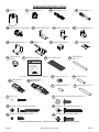
HARDWARE IDENTIFICATION
Screws are shown actual size. You may receive extra hardware with your unit.
WARNING
Never use this furniture with a TV that is
too large or too heavy. Severe injury or
death can occur. The TV and furniture
will be unstable and may tip.
-The TV must less than 50 lbs.
-The base of the TV must be able to sit
completely on this shelf.
Refer to instruction book for complete
safety information.
Note: This is a permanent label. Do not
try to remove. Surface will be damaged.
08/05 2 6 9 2 2 0 269220
WARNING LABEL - 1
1L
(Refer to the last step for proper location and application)
3M
ANTI-SKID PAD - 1
FOOT - 1
23E
33M
DECORATIVE
END - 2
34M
DECORATIVE
BACKPLATE - 1
69K
DECORATIVE
KNOB - 1
32M
DECORATIVE
POST - 2
CORNER BRACKET - 4
31G 27H
HINGE - 2
BLACK 9/16" LARGE HEAD SCREW - 61
1S
METAL BRACKET - 4
4G
NAIL - 45
1N
METAL PIN - 8
1R
RUBBER SLEEVE - 8
2R
CAM DOWEL - 12
2F
HIDDEN CAM - 20
1F
BLACK 1-7/8" FLAT HEAD SCREW - 5
2S
SAFETY BRACKET - 1
1G
MAGNETIC CATCH - 1
2I
STRIKE PLATE - 1
6I
BLACK 1/2" FLAT HEAD SCREW - 1
11S
LONG METAL PIN - 2
3R
SILVER 3/4" MACHINE SCREW - 2
20S
SILVER 1-1/2" MACHINE SCREW - 1
95S
TWIST-LOCK
®
FASTENER - 3
10F
ANGLE BRACKET - 10
27G
CAM SCREW - 8
8F
CAM COVER - 8
36P
Page 4 www.sauder.com/services 414723

Look for this icon. It means a video
assembly tip is available at:
www.sauder.com/services/tips
1
1
S
t
e
p
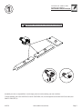
Assemble your unit on a carpeted fl oor or on the empty carton to avoid scratching your unit or the fl oor.
To begin assembly, push a SAUDER TWIST-LOCK
®
FASTENER (10F) into the large holes in the MOLDINGS (M and N) and
SMALL UPRIGHT (D).
Page 5
www.sauder.com/services414723
Do not tighten the TWIST-LOCK® FASTENERS in this step.
10F
N
M
D

2
2
S
t
e
p
Page 6 www.sauder.com/services 414723
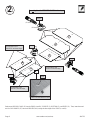
Push twenty HIDDEN CAMS (1F) into the ENDS (A and B), UPRIGHT (C), BOTTOM (F), and SHELF (G). Then, insert the metal
end of a CAM DOWEL (2F) into each HIDDEN CAM, except the short edges of the ENDS (A and B).
Do not tighten the HIDDEN CAMS in this step.
Do not insert CAM
DOWELS into these edges.
Do not insert CAM
DOWELS into this edge.
Arrow
(12 used)
(20 used)
Arrow
Arrow
1F
1F
1F
1F
2F
2F
Insert the metal end of the CAM
DOWEL into the HIDDEN CAM.
Arrow
Arrow
Do not insert CAM
DOWELS into this edge.
A
B
C
G
F

3
3
S
t
e
p
Page 7
www.sauder.com/services414723
(10 used in this step)
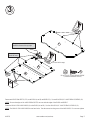
Fasten ten ANGLE BRACKETS (27G) to the ENDS (A and B) and SHELF (G). Use ten BLACK 9/16" LARGE HEAD SCREWS (1S).
NOTE: Be sure the edges of the ANGLE BRACKETS are even with the edges of the ENDS and SHELF.
Fasten the SMALL END MOLDINGS (R) to the ENDS (A and B). Use four BLACK 9/16" LARGE HEAD SCREWS (1S).
NOTE: The SMALL END MOLDINGS do not have holes. Turn the screws into the groove of the MOLDINGS. Do not over tighten.
BLACK 9/16" LARGE HEAD SCREW
(14 used for the BRACKETS)
1S
27G
27G
A
B
G
These edges
should be even.
The groove in the MOLDINGS (R)
should be closer to the top edge.
27G
R
R

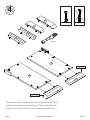
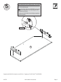
Turn eight CAM SCREWS (8F) into the MOLDINGS (M and N) and BASES (P and Q).
Fasten the RIGHT BASE (P) to the RIGHT END (A). Tighten two HIDDEN CAMS.
Fasten the LEFT BASE (Q) to the LEFT END (B). Tighten two HIDDEN CAMS.
4
4
S
t
e
p
Page 8 www.sauder.com/services 414723
8F
Unfi nished surface
Unfi nished surface
Q
Q
P
P
A
M
N
Angled edge
Angled edge
B
(8 used)

5
5
S
t
e
p
Page 9
www.sauder.com/services414723
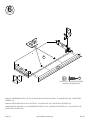
Fasten the MOLDINGS (M and N) to the TOP (E). Tighten two TWIST-LOCK
®
FASTENERS.
How to use the SAUDER TWIST-LOCK
®
FASTENER
1. Insert the dowel end of the FASTENER into the
hole of the adjoining part.
NOTE: The dowel end of the FASTENER must remain
fully inserted in the hole of the adjoining part while
locking the FASTENER.
2. Tighten the FASTENER with a Phillips screwdriver
as tight as possible.
Dowel end
E
M
N

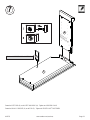
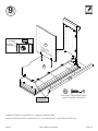
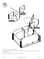
Fasten two CORNER BRACKETS (31G) to the MOLDINGS (M and N) and TOP (E). Use eight BLACK 9/16" LARGE HEAD
SCREWS (1S).
Fasten two METAL BRACKETS (4G) to the TOP (E). Use two BLACK 9/16" LARGE HEAD SCREWS (1S).
Fasten the FRONT MOLDING (U) to the CORNER BRACKETS (31G) and METAL BRACKETS (4G). Use six BLACK 9/16"
LARGE HEAD SCREWS (1S).
6
6
S
t
e
p
Page 10 www.sauder.com/services 414723
31G
31G
M
N
BLACK 9/16" LARGE HEAD SCREW
(16 used for the BRACKETS)
1S
4G
E
U

7
7
S
t
e
p
Page 11
www.sauder.com/services414723
N
E
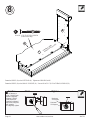
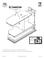
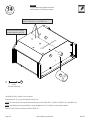
Fasten the LEFT END (B) to the LEFT MOLDING (N). Tighten two HIDDEN CAMS.
Fasten the SMALL UPRIGHT (D) to the TOP (E). Tighten the TWIST-LOCK
®
FASTENER.
B
Surface with TWIST-LOCK
®
FASTENER
Surface with
HIDDEN CAMS
D

Fasten the SHELF (G) to the LEFT END (B). Tighten two HIDDEN CAMS.
Fasten the SHELF (G) to the SMALL UPRIGHT (D). Use two BLACK 1-7/8" FLAT HEAD SCREWS (2S).
8
8
S
t
e
p
Page 12 www.sauder.com/services 414723
Caution
Risk of damage or
injury. Hidden Cams
must be completely
tightened. Hidden
Cams that are not
completely tightened
may loosen, and parts
may separate.
To completely tighten:
Start Tighten
Arrow
Arrow
Maximum
210 degrees
Minimum
190 degrees
G
BLACK 1-7/8" FLAT HEAD SCREW
(2 used in this step)
2S
D
B
Surface with
HIDDEN CAMS

9
9
S
t
e
p
Page 13
www.sauder.com/services414723
G
Fasten the UPRIGHT (C) to the SHELF (G). Tighten two HIDDEN CAMS.
Fasten the SHELF MOLDING (S) to the SHELF (G). Use four BLACK 9/16" LARGE HEAD SCREWS (1S).
Maximum
210 degrees
Minimum
190 degrees
Arrow
C
Surface with
HIDDEN CAMS
S
These edges
should be even.
BLACK 9/16" LARGE HEAD SCREW
(4 used for the SHELF MOLDING)
1S

Fasten the BOTTOM (F) to the LEFT BASE (Q). Tighten two HIDDEN CAMS.
Tighten the BOTTOM (F) to the UPRIGHT (C). Use two BLACK 1-7/8" FLAT HEAD SCREWS (2S).
10
10
S
t
e
p
Page 14 www.sauder.com/services 414723
Maximum
210 degrees
Minimum
190 degrees
Arrow
F
Surface with
HIDDEN CAMS
BLACK 1-7/8" FLAT HEAD SCREW
(2 used in this step)
2S
C
Q

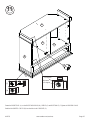
Fasten the RIGHT END (A) to the RIGHT MOLDING (M), SHELF (G) and BOTTOM (F). Tighten six HIDDEN CAMS.
Push the MAGNETIC CATCH (2I) into the hole in the UPRIGHT (C).
11
11
S
t
e
p
Page 15
www.sauder.com/services414723
C
Maximum
210 degrees
Minimum
190 degrees
Arrow
A
F
G
2I
M

Fasten an END MOLDING (T) to the RIGHT END (A). Tighten two HIDDEN CAMS.
Fasten the other END MOLDING (T) to the LEFT END (B). Use two BLACK 9/16" LARGE HEAD SCREWS (1S).
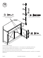
Fasten two CORNER BRACKETS (31G) to the BASES (P and Q) and BOTTOM (F). Use eight BLACK 9/16" LARGE HEAD SCREWS (1S).
Fasten two METAL BRACKETS (4G) to the BOTTOM (F). Use two BLACK 9/16" LARGE HEAD SCREWS (1S).
NOTE: Be sure the BRACKETS are even with the edges of the BOTTOM.
Fasten the BASE (O) to the CORNER BRACKETS (31G) and METAL BRACKETS (4G). Use six BLACK 9/16" LARGE HEAD
SCREWS (1S).
12
12
S
t
e
p
Page 16 www.sauder.com/services 414723
31G
31G
O
F
P
Q
BLACK 9/16" LARGE HEAD SCREW
(18 used in this step)
1S
4G
A
T
T
B
Maximum
210 degrees
Minimum
190 degrees
Arrow
Use the small holes in
this MOLDING (T).
These edges
should be even.
These edges
should be even.

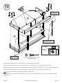
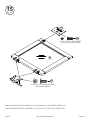
Carefully turn your unit over onto its front edges.
Insert two LONG METAL PINS (3R) into the holes in the CROSS SHELF (H). Push two SMALL CROSS SHELVES (I) over the
LONG METAL PINS.
Carefully insert the CROSS SHELF assembly into the opening as shown.
13
13
S
t
e
p
Page 17
www.sauder.com/services414723
3R
Finished edge
Finished edge
Finished edge
H
H
I
I
I
I

14
14
S
t
e
p
Page 18 www.sauder.com/services 414723
Unfold the BACK (J) and lay it over your unit.
Fasten the BACK (J) to your unit using the NAILS (1N).
NOTE: Be sure to tap NAILS into the holes that line up over the UPRIGHT (C), SMALL UPRIGHT (D), and SHELF (G).
NOTE: Perforations have been provided for access through the BACK. Carefully cut out the holes needed.
Push the FOOT (23E) into the hole in the BOTTOM (F).
Do not stand the unit upright without the
BACK fastened. The unit may collapse.
Caution
NAIL
(45 used in this step)
1N
These holes must line up over the URIGHT (C),
SMALL UPRIGHT (D), and SHELF (G).
Unfi nished surface
The BACK should be against
the bottom surface of the TOP.
J
23E
F

Fasten the HINGES (27H) to the DOOR (K). Use four BLACK 9/16" LARGE HEAD SCREWS (1S).
Fasten the STRIKE PLATE (6I) to the DOOR (K). Use a BLACK 1/2" FLAT HEAD SCREW (11S).
15
15
S
t
e
p
Page 19
www.sauder.com/services414723
BLACK 9/16" LARGE HEAD SCREW
(4 used for the HINGES)
1S
27H
6I
BLACK 1/2" FLAT HEAD SCREW
(1 used for the STRIKE PLATE)
11S
K

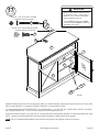
Carefully stand your unit upright.
Fasten the DOOR (K) to the RIGHT END MOLDING (T). Use four BLACK 9/16" LARGE HEAD SCREWS (1S).
Fasten the DECORATIVE ENDS (33M) to the DOOR (K). Use two SILVER 3/4" MACHINE SCREWS (20S).
Insert a DECORATIVE POST (32M) into the DECORATIVE ENDS.
Fasten the DECORATIVE BACKPLATE (34M) and DECORATIVE KNOB (69K) to the DOOR. Use a SILVER 1-1/2" MACHINE
SCREW (95S).
16
16
S
t
e
p
Page 20 www.sauder.com/services 414723
BLACK 9/16" LARGE HEAD SCREW
(4 used for the HINGES)
1S
K
32M
32M
33M
33M
34M
69K
SILVER 3/4" MACHINE SCREW
(2 used for the DECORATIVE ENDS
20S
SILVER 1-1/2"" MACHINE SCREW
(1 used for the BACKPLATE and KNOB)
95S
T
Page is loading ...
Page is loading ...
Page is loading ...
Page is loading ...
Page is loading ...
Page is loading ...
Page is loading ...
Page is loading ...
Page is loading ...
Page is loading ...
Page is loading ...
Page is loading ...
-
 1
1
-
 2
2
-
 3
3
-
 4
4
-
 5
5
-
 6
6
-
 7
7
-
 8
8
-
 9
9
-
 10
10
-
 11
11
-
 12
12
-
 13
13
-
 14
14
-
 15
15
-
 16
16
-
 17
17
-
 18
18
-
 19
19
-
 20
20
-
 21
21
-
 22
22
-
 23
23
-
 24
24
-
 25
25
-
 26
26
-
 27
27
-
 28
28
-
 29
29
-
 30
30
-
 31
31
-
 32
32


Sauder 414723 Installation guide
- Category
- Storage chests & cabinets & trunks
- Type
- Installation guide
Ask a question and I''ll find the answer in the document
Finding information in a document is now easier with AI
in other languages
- français: Sauder 414723 Guide d'installation
- español: Sauder 414723 Guía de instalación
Related papers
-
Sauder HomePlus Collection 411967 Operating instructions
-
-
-
-
-
-
-
-
-
Other documents
-
Elation FT-20S Power Supply Base User manual
-
ROOMS TO GO 21218424 Assembly Instructions
-
Meyer&Cross TV1378 User manual
-
Dynex DX-WD1335 User manual
-
Insignia NS-39DR510NA17 User guide
-
Bush RFV160RG-03 Assembly Instructions
-
Bell'O SFP-9901HG User manual
-
-
-