OPERATING INSTRUCTIONS (continued)
Resetting the Manual Reset Limit Control
Warranty
Fault Codes
Digital Display Reads Problem Solution
F
NO
NO
HEAT
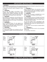
Model:
Volts:
Watts:
WARNING! TO AVOID ELECTRICAL SHOCK
Disconnect power at circuit breaker before servicing.
Do not operate without grill.
cadetheat.com
Vancouver, WA
Mfg Date:
Before pushing
RESET button see
Owner’s Guide
for display fault
codes and other
troubleshooting
information.
3108579
conforms
to UL STD
2021
072xxx
For more effective and safer operation and to prolong the life of
the heater, read the Owner’s Guide and follow the maintenance
instructions. Failure to properly maintain the heater will void any
warranty and may cause the heater to function improperly. War-
ranties are non transferable and apply to original consumer only.
Warranty terms are set out below.
LIMITED FIVE-YEAR WARRANTY: Cadet will repair or replace
any Energy Plus (CE) heater found to be defective within ve
years after the date of purchase.
These warranties do not apply:
1. Damage occurs to the product through improper installation or
incorrect supply voltage;
2. Damage occurs to the product through improper maintenance,
misuse, abuse, accident, or alteration;
3. The product is serviced by anyone other than Cadet;
4. If the date of manufacture of the product cannot be deter-
mined;
5. If the product is damaged during shipping through no fault of
Cadet.
6. CADET’S WARRANTY IS LIMITED TO REPAIR OR RE-
PLACEMENT AS SET OUT HEREIN. CADET SHALL NOT BE
LIABLE FOR DAMAGES SUCH AS PROPERTY DAMAGE OR
FOR CONSEQUENTIAL DAMAGES AND/OR INCIDENTAL EX-
PENSES RESULTING FROM BREACH OF THESE WRITTEN
WARRANTIES OR ANY EXPRESS OR IMPLIED WARRANTY.
7. IN THE EVENT CADET ELECTS TO REPLACE ANY PART
OF YOUR CADET PRODUCT, THE REPLACEMENT PARTS
ARE SUBJECT TO THE SAME WARRANTIES AS THE PROD-
UCT. THE INSTALLATION OF REPLACEMENT PARTS DOES
NOT MODIFY OR EXTEND THE UNDERLYING WARRANTIES.
REPLACEMENT OR REPAIR OF ANY CADET PRODUCT OR
PART DOES NOT CREATE ANY NEW WARRANTIES.
8. These warranties give you specic legal rights, and you may
also have other rights which vary from state to state. Cadet nei-
ther assumes, nor authorizes anyone to assume for it, any other
obligation or liability in connection with its products other than as
set out herein.
If you believe your Cadet product is defective, please contact
Cadet Manufacturing Co. at 360-693-2505, during the warranty
period, for instructions on how to have the repair or replacement
processed. Warranty claims made after the warranty period has
expired will be denied. Products returned without authorization
will be refused.
Parts and Service
Visit cadetheat.com/parts-service for information on where to
obtain parts and service.
Reduce-Reuse-Recycle
This product is made primarily of recyclable materials. You
can reduce your carbon footprint by recycling this product at
the end of its useful life. Contact your local recycling support
center for further recycling instructions.
The heater is protected by a temperature-limiting control. The manual reset temperature limit control is designed to open the heater
circuit when excessive operating temperatures are detected. The problem must be assessed (typically the heater is blocked or needs
cleaning) and the limit must be reset to resume operation.
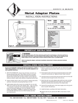
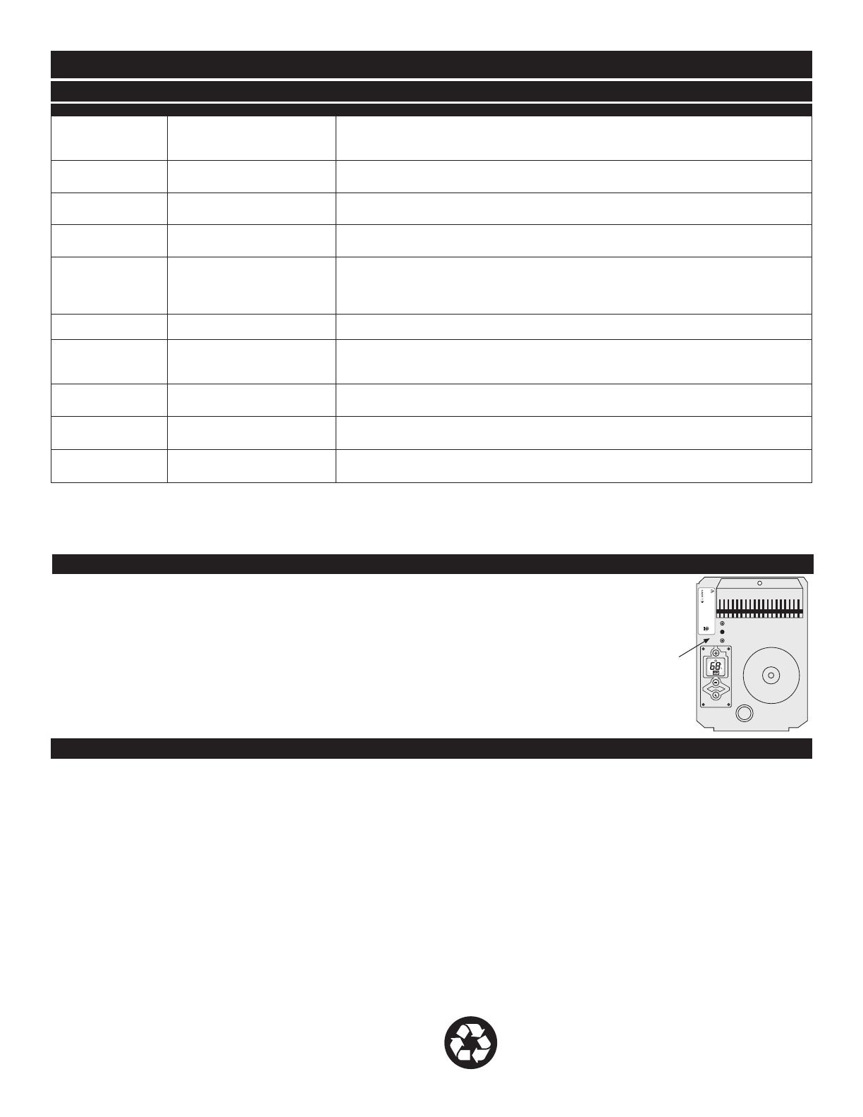
About the Manual Reset Temperature Limit Control
Resetting the Manual Reset Temperature Limit Control
If the manual reset limit control has opened the heater circuit due to excessive operating tempera-
tures, the heater will not work until the manual reset limit button is pressed.
The “manual reset limit button” is the red button located on the upper left side of your heater, behind
the grill louvers located just above the digital temperature display.
After allowing the unit to cool for at least 10 minutes and resolving the problem causing the limit to
trip (typically the heater is blocked or needs cleaning); use a narrow object such as a ball-point pen to
access the manual reset button through the upper-left center section of the heater grill. Press FIRM-
LY and be sure to listen and feel for a click, indicating it has been reset.
No Display No power, internal fuse
blown, internal control faulty
Check that power is being supplied to heater; if operating on generator power,
make sure line frequency is correct; if display still doesn’t turn on then control is
defective and heater assembly must be replaced.
F1
Grill is interfering with
buttons
Turn power off at circuit breaker, realign grill so buttons can push freely. Turn pow-
er back on at circuit breaker.
F2
Wrong voltage selector key
Turn power off at the circuit breaker, remove 120V white key, install 240V black
key, turn power back on at circuit breaker.
F3
Wrong voltage selector key
Turn power off at the circuit breaker, remove 240V black key, install 120V white
key, turn power back on at circuit breaker.
F4
1. Line voltage is too low
2. Loose wire connections,
or black/white key is not
fully engaged
1. Clears automatically when line voltage returns to normal.
2. Check wire connections and that black or white key is securely in place.
F6
Line voltage is too high Clears automatically when line voltage returns to normal.
F7
Thermal limit (temperature
limiting control) tripped
Inspect heater for blockage, obstruction, and/or proper clearance. Move rocker
switch to center (NO HEAT) position and wait for heater to cool. Push manual reset
limit button per the MAINTAINING YOUR HEATER instructions (Page 8).
F8
Internal control fault
Disconnect power, reconnect power. If F8 code returns, control is faulty. Replace
heater assembly.
12
No voltage selector key
installed
Turn power off at the circuit breaker, install 120V white key, turn power back on at
circuit breaker.
24
No voltage selector key
installed
Turn power off at the circuit breaker, install 240V black key, turn power back on at
circuit breaker.
Page 7
Manual
Reset
Limit
Button