
570 Easy Entry™ Receiver and 575 Transmitter
Description
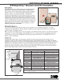
The Model 570 Easy Entry™ RF Series Receivers and Model 575 Key
Ring Transmitters are used to remotely open or close a garage
door and arm or disarm DMP XRSuper6, XR20, and XR40 Command
Processor™ Panels. For a quick and simple installation, the 570
Receiver connects to the panel keypad bus. The Model 575
Transmitter provides buttons to arm or disarm the panel, activate
a garage door, and provides a panic button for emergencies. Every
time a button is pressed, the transmitter sends one of four billion
randomly changing codes that ensure state-of-the-art anti-scanning
security. The 570 Receiver includes a push-button and LED for easy
programming and a wire harness for easy installation. In addition,
a high intensity LED on a mounting plate is included for a visual
indication of the panel armed status.
Wiring the Receiver
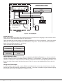
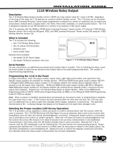
Connect the 570 Receiver harness Red, Yellow, Green, and Black wires to the panel keypad bus. The panel
connections are marked RED (7), YEL (8), GRN (9), and BLK (10) and correspond to the same color wires as the
receiver harness. See Figures 2 and 3.
Note: To program the 570 Receiver, use any LCD keypad, such as Models 690/790, 693/793, any 7000 Series Thinline
or Aqualite™. Do not use VFD keypads, such as Models 770 or 771. Also note that only one keypad and NO other
devices may be connected to the keypad bus when programming the 570 Receiver. The keypad must be set to
Address 1 when programming.
Garage Door
All garage door openers have a wall-mounted, push-button switch that activates the door through a 2-wire
connection. These two wires connect the push-button switch to the garage door motor. The 2 Amp relay output
provided from the receiver is turned on or off using the middle button on the 575 Key Ring Transmitter. Connect the
Red/White (N/O) and White (common) wires of the 570 Receiver harness in parallel with the existing push-button
switch wires or to the garage door motor. When connecting at the garage door motor, trace the wires from the
push-button switch to the motor to determine the correct connection. Most garage door motors use terminals #1
and #2, except MOM Crusader models, which use terminals #2 and #3.
Receiver Harness Wiring
Wire Color Description Connection
Blue or Purple*Switched ground (–) Output Armed Status LED (Black wire)
Black Ground panel - Black (10)
Red +12 VDC panel - Red (7)
Blue/Green Optional Relay N/C Optional Accessories
White/Brown Optional Relay N/O Optional Accessories
Brown Optional Relay Common Optional Accessories
White Garage Door Relay Common Garage Door Switch
Red/White Garage Door Relay N/O Garage Door Switch
Gray Switched Ground (–) Output Garage Door Timed Output
Yellow Data Transmit to panel panel - Yellow (8)
Green Data Receive from panel panel - Green (9)
*Note: The 570 receiver harness may include either a Blue or Purple wire
for this connection.
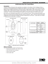
Figure 2: Model 570 RF Receiver
BLUE or PURPLE
BLACK
RED
BLUE/GREEN
WHITE/BROWN
BROWN
WHITE
RED/WHITE
GRAY
YELLOW
GREEN
Option Header #1
Option Header #2
RF Antenna
Figure 1: Status LED, Transmitter, Receiver
INSTALLATION GUIDE

XRSuper6, XR20, or XR40
Command Processor™ Panel
7 8 9 10
RED
YEL
GRN
BLK
BLU or PRP
BLK
RED
WHT
RED/WHT
YEL
GRN
1 2 3 4 5 6 7 8 9 10 1112
Option
Headers
LED #1 #2
Switch Programming
Button
LED
RF Antenna
The Switch must be to the
right for the 570 Receiver
to operate properly.
Armed Status LED
RED
Blue or
Purple
–
+
Garage Door Connection
1 2 3
Model 570 Receiver
(End Views)
Figure 3: Wiring Diagram
Armed Status LED
Mount the included mounting plate and Armed Status LED in a location such as the garage or the front door where
visual indicator of the panel armed status can easily be seen.
The Armed Status LED includes a Purple wire negative and Red wire (+12 VDC) for installation. Connect the Status
LED Purple wire negative to the 570 Receiver harness Blue or Purple wire. Connect the Armed Status LED Red or
Purple wire to the panel terminal 7. See Figure 3.
The Armed Status LED operates as shown:
LED System Status
Slow Blinking Exit Delay
On Armed
Off Disarmed
Fast Blinking Alarm
Optional Accessory Relay
When the panic button operation is not enabled (see Operating the Key Ring Transmitter), a relay is provided for
optional accessories control such as Malibu lighting, sprinklers, or X-10 automation. The output provided from the
receiver is a 2 Amp form C relay and turns On or Off using the bottom button on the 575 Key Ring Transmitter. The
Brown wire is the relay common, the Blue/Green wire is the N/C contact, and the White/Brown wire is the N/O
contact.
Garage Door Timed Output
A switched negative ground output, rated at 500mA, is provided on the receiver Gray wire and turns on for three
minutes every time the transmitter middle button is pressed. This output is available to trigger additional lighting
that may be desired when the garage door is opened or closed.
Digital Monitoring Products 570/575 Easy Entry™ Receiver/Transmitter Installation
2
570/575 Easy Entry™ Receiver/Transmitter Installation Digital Monitoring Products
3

Programming the Receiver
Note: When programming the 570 Receiver, only one keypad and NO other devices can be connected to the keypad
bus. When you nish programming, you may then connect any other keypads and devices to the keypad bus.
The 570 RF Series Receiver arms or disarms the panel by sending a 4-digit user code just as if the code was entered
at a keypad. The user code must be added to the 570 and must also be programmed into the panel. See the
XRSuper6 User’s Guide (LT-0622), XR20 User’s Guide (LT-0303), and XR40 User’s Guide (LT-0494).
Note: You must enter the 4-digit user code into the panel before you can add the user code to the 570. Refer to the
panel User’s Guide as discussed above.
Add the User Code
The single user code is added by pressing and holding the receiver programming button (see Figure 2). The receiver
programming LED turns on for three seconds and then turns off. When the LED turns off, release the programming
button and the LED ashes indicating user code programming mode is enabled. While the programming LED is
ashing, enter the 4-digit user code on the keypad. After the fourth digit is entered, the LED turns off indicating the
user code is learned.
Note: Do not have any zone expansion devices connected to the keypad bus when adding the user code.
Add and Delete Key Ring Transmitters
To learn a transmitter, press the receiver programming button once to turn the programming LED on steady. While
the LED is on, press the key ring transmitter top button three times. The LED turns off indicating the transmitter
has been learned. Up to seven transmitters can be learned. The eighth transmitter learned overwrites the rst
transmitter learned.
To delete a transmitter from the receiver, all transmitters will be deleted. Press and hold the receiver programming
button for seven seconds. During this time, the programming LED pulses on, off, and on again. After the LED turns
on the second time, the receiver memory is cleared and all transmitters are deleted.
Set Option Header #1: Panic or Relay
When the receiver jumper is installed on option header #1 (see Figures 1 and 2), the key ring transmitter bottom
button operates as a Panic button. This is equivalent to pressing the badge panic keys on a DMP keypad.
Set Option Header #2: Relay Momentary or Toggle
When the receiver jumper is not installed on option header #1, the key ring transmitter bottom button operates the
optional receiver accessory relay. The relay operation is determined by receiver option header #2.
When the jumper is installed on option header #2, pressing the transmitter bottom button causes the relay to turn
on for one second and then turn off. Each press causes the relay to turn on and then off.
When the jumper is not installed on option header #2, pressing the transmitter bottom button causes the relay
COMMON to toggle to the N/O or N/C contact. Each press causes the relay to change state.
Digital Monitoring Products 570/575 Easy Entry™ Receiver/Transmitter Installation
2
570/575 Easy Entry™ Receiver/Transmitter Installation Digital Monitoring Products
3

LT-0411 (10/05) © 2005 Digital Monitoring Products Inc.
Operating the Key Ring Transmitter
The Model 575 Key Ring Transmitter provides three buttons for operation. The small LED on the transmitter lights
any time a button is pressed.
Transmitter Button Operation
Top Alarm On/Off/Perimeter
Middle Garage Door OPEN/CLOSE
Bottom PANIC or Optional Accessories
Top Button
Arming and Disarming the System
Pressing the 575 Key Ring Transmitter top button sends the 4-digit user code to the panel. This code arms or disarms
all panel areas. The Armed Status LED lights indicating an armed status. Pressing the top button again disarms the
system.
Pressing the top button for more than three seconds arms the perimeter protection only. Pressing the top button
again disarms the system.
Middle Button
Garage Door
The timed output can be used to trigger additional accessories such as driveway, porch, or Malibu lighting. Pressing
the key ring transmitter middle button activates the garage door.
Bottom Button
The key ring transmitter bottom button may be set up to send either a panic signal or turn optional accessories on or
off.
Panic Button
Pressing the bottom button for more than three seconds sends the Panic signal. This is equivalent to pressing the
Badge Panic keys on a keypad.
Optional Accessories
Pressing the bottom button on the transmitter causes the optional accessories to turn on or off.
Central Station Reporting
When the key ring transmitter bottom button is programmed as a Panic Button, pressing the button for three or
more seconds sends the panic signal to the central station. The panic displays at the central station receiver as
Zone 19 Address 8.
Specications
Remote Transmitter
Range 150 Feet
Battery Type 23A 12 VDC Mini
(replace yearly)
Frequency 303 MHz
Temperature Range 32°F to 120°F
Dimensions 2.25" H x 1.5" W x 0.5" D
Receiver
Current Draw
Power 12 VDC from panel
Standby 20mA
Frequency 303 MHz
Temperature Range -5°F to 160°F
Dimensions 3" H x 3.5" W x 1.125" D
Garage Door/Optional Accessory
Relay Contacts 2 Amps
800-641-4282
www.dmp.com
Made in the USA
INTRUSION • FIRE • ACCESS • NETWORKS
2500 North Partnership Boulevard
Springfield, Missouri 65803-8877
-
 1
1
-
 2
2
-
 3
3
-
 4
4


DMP Electronics 570 Easy EntryTM Receiver and 575 Transmitter Installation guide
- Type
- Installation guide
- This manual is also suitable for
Ask a question and I''ll find the answer in the document
Finding information in a document is now easier with AI
Related papers


Other documents
-
ADEMCO VISTA-50PEN Installation And Setup Manual
-
-
Directed Electronics 560XV Installation guide
-
Viper 881 XP Installation guide
-
Directed Electronics Python 990 Installation guide
-
ADEMCO VISTA-50P User manual
-
Python 881 XP Installation guide
-
-
-
Directed Electronics 791 XV Installation guide