
PAGE 1
Congratulations on purchasing your new Lancaster Water Softener. This unit is designed to give
you many years of trouble free service. When installed in accordance with the following instructions
and if given reasonable care, clear-soft water will be the result. For servicing and future inspection
purposes, please le this booklet with your important documents.
In the event that you need assistance for servicing your water softener, please rst contact the
professional contractor who installed the system.
ELECTRONIC WATER SOFTENER WITH
THE X-FACTOR CONTROL VALVE
COMMERCIAL SERIES
LX15, LX2 & LX2QC
INSTALLATION, OPERATING AND
SERVICE MANUAL

PAGE 2
MODEL NO.
JOB SPECIFICATIONS
WATER TEST AT TIME OF INSTALLATION
Hardness CaCo3 (gpg)
Iron (ppm)
pH
Other:
SIZING INFORMATION
All Water is Softened Except:
Rear Hose Bib Front Hose Bib Kitchen Cold Toilets All Cold
Other
The average family uses 50 gallons per person daily for all water uses in the home.
Daily Water Usage (Gallons/Person)
x Family Size (Number of people in family)
= Total Gallons Per Day
x Grains Per Gallon of hardness
(Note: Add 4 grains per gallon of hardness for each ppm iron for total compensated hardness)
= Total Grains per Day
INSTALLATION DATE
SERIAL NUMBER
INSTALLER NAME PHONE
ADDRESS
TABLE OF CONTENTS
Job Specications ......................................................................................................................... 2
Inspection, Resin Loading and Assembly ...................................................................................... 3
Pre-Installation Review ................................................................................................................. 4
General Installation and Service Warnings .................................................................................. 4
Bypass Valve Operation ............................................................................................................... 5
Installation Instructions, Diagrams ................................................................................................ 6-9
Placing Softener into Service ....................................................................................................... 10
General Operation ........................................................................................................................ 10
Set Time of Day ............................................................................................................................ 11
Adjust Hardness, Days Between Regenerations or Time of Regeneration .................................. 11-12
Low Battery.................................................................................................................................... 12
Contact Screen Programming ...................................................................................................... 12
Specications ............................................................................................................................... 13
Parts Diagrams ............................................................................................................................. 14-25
Service Instructions ...................................................................................................................... 26-29
Troubleshooting ............................................................................................................................ 30-33
(For more accuracy, take water meter readings during average or peak days. Water bills may also be used to
determine daily water usage. For commercial application usage estimation, consult factory if assistance is required)

PAGE 3
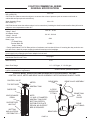
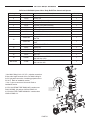
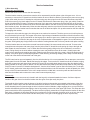
ION EXCHANGE
RESIN
RISER PIPE
BOTTOM
HUB & LATERAL
DISTRIBUTOR
CONTROL VALVE
TOP DIFFUSER
MINERAL TANK
U1007 FUNNEL
WATER LEVEL
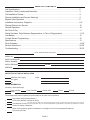
INSPECTION, RESIN LOADING AND ASSEMBLY
Commercial water softeners are shipped in multiple cartons:
- mineral tank with bottom distributor and riser pipe
- brine tank assembly
- control valve with meter
- optional alternator valve or no hard water bypass valve
- bag(s) of gravel support bed (for 21" diameter and larger mineral tanks)
- 1 cubic foot bags of water softener resin
Quantity of components are specific for the individual type softening system ordered. Refer to specification
data sheet and/or drawing or consult factory.
Inspect the shipping cartons and equipment for possible shipping damage or lost parts. If damage is present,
notify the transportation company. The manufacturer is not responsible for damage or lost parts in shipment.
Do not mistakenly discard any small parts bags when unpacking the system.
BEFORE LOADING THE MINERAL TANK WITH GRAVEL FOLLOWED BY RESIN,
INSPECT THE BOTTOM LATERALS FOR ANY DAMAGE THAT MAY HAVE OCCURRED DURING SHIPPING.
THE LATERALS MUST BE REPLACED IF THERE IS ANY DAMAGE.
LOADING AND ASSEMBLING THE MINERAL TANK:
1. Place the mineral tank where you want to install it, making sure it is
on a clean, level and firm surface.
2. PLUG OR TAPE THE TOP OF THE RISER PIPE to keep gravel
and resin from entering. Gravel and resin must not enter riser pipe.
3. BEFORE LOADING THE GRAVEL AND RESIN, FILL THE
MINERAL TANK APPROXIMATELY 1/3 FULL OF WATER.
The water will act as a cushion to protect the bottom laterals from
damage while filling the tank with gravel and resin.
4. Using a U1007 commercial tank funnel is recommended (funnel is
ordered separately). The U1007 funnel snaps into 4" and 6"
mineral tank openings for stability when pouring gravel and resin.
The neck of the funnel allows air to escape the mineral tank while
gravel and resin are poured in.
5. Load the gravel support bed first, followed by the resin. While filling,
be careful to keep the riser pipe centered as best you can. The resin
beads tend to stick to the funnel. Filling slowly with a small scoop
to pour the resin into the funnel, using water SPARINGLY to speed
flow through the funnel, will work better than trying to fill too fast.
6. After the loading is complete, remove the funnel, clean the tank
opening to remove resin beads from the tank opening. Note that the
resin will only fill the mineral tank approximately 1/2 to 3/4 full. The
mineral tank should NEVER be filled to the top with resin. This
remaining open space is called freeboard and is necessary for the
resin to have room to move during the backwash cycle.
7. REMOVE THE PLUG OR TAPE FROM THE TOP OF THE RISER
PIPE.
8. FINISH FILLING THE MINERAL TANK WITH WATER. This will
eliminate air space and prevent excessive air-head pressure when
the water softener is pressurized.
9. The control valve must now be screwed onto the mineral tank.
Be sure the mineral tank's o-ring sealing surface is clean. NO pipe
dope should be used on threads. As you start to screw the control
valve onto the tank, make sure the hole in the center of the control
valve fits over the riser pipe. The control valve should be hand-
tightened, snugly, clockwise.
GRAVEL
SUPPORT BED
#20 FLINT
NOTE- 14" AND 16" DIAMETER MINERAL TANKS ARE BOTTOM
VORTECH DISTRIBUTOR PLATE DESIGN; NO GRAVEL SUPPORT
BED IS REQUIRED.
Click to buy NOW!
P
D
F
-
X
C
H
A
N
G
E
w
w
w
.
d
o
c
u
-
t
r
a
c
k
.
c
o
m
Click to buy NOW!
P
D
F
-
X
C
H
A
N
G
E
w
w
w
.
d
o
c
u
-
t
r
a
c
k
.
c
o
m
If your control valve is a top or side-
mount clamp connection, or uses a ange base, consult factory if
you have questions.

PAGE 4
The control valve and ttings are not designed to support
the weight of the system or the plumbing.
Do not use Vaseline, oils, other hydrocarbon lubricants or
spray silicone anywhere. A silicone lubricant may be used
on black o-rings but is not necessary. Avoid any type of
lubricants, including silicone, on the clear lip seals.
Hydrocarbons such as kerosene, benzene, gasoline,
etc., may damage products that contain o-rings or
plastic components. Exposure to such hydrocarbons
may cause the products to leak. Do not use the
product(s) contained in this document on water
supplies that contain hydrocarbons such as kerosene,
benzene, gasoline, etc.
This water meter should not be used as the primary
monitoring device for critical or health eect
applications.
The V3151 nuts are designed to be unscrewed or
tightened by hand or with the special plastic wrench
(V3193). If necessary, pliers can be used to unscrew the
nut. Do not use a pipe wrench to tighten or loosen nuts.
Do not place a screw driver in the slots on nuts and/or tap
with a hammer.
Do not use pipe dope or other sealants on threads. Use
of pipe dope may break down the plastics in the control
valve. Use Teon tape on the threaded inlet, outlet and
drain ttings. Teon tape is not necessary on the V3151
nut connection because of o-rings seals.
After completing any valve maintenance involving the
drive assembly or the drive cap assembly and pistons,
unplug power source jack from the printed circuit board
(black wire) and plug back in or press and hold NEXT
and REGEN buttons for 3 seconds. This resets the electronics
and establishes the service piston position. The display
should ash the software version and then reset the valve
to the service position.
Solder joints near the drain must be done prior to
connecting the drain line ow control tting. Leave at least
6” between the drain line control tting and solder joints
when soldering pipes that are connected on the drain
line control tting. Failure to do this could cause interior
damage to the drain line ow control tting.
Install grounding strap on metal pipes.
This water softener is not to be used for treating
water that is microbiologically unsafe or of unknown
quality without adequate disinfection before or after
treatment.
GENERAL INSTALLATION
AND SERVICE WARNINGS
PRE-INSTALLATION
REVIEW
WATER QUALITY: If sand or sediment is present in
the water supply, a sediment lter should be installed
ahead of the water softener. Your water softener has
been designed to adequately reduce hardness from
levels up to 100 grains per gallon. Ferrous bicarbonate
iron levels up to 0.5 ppm can also be reduced. This is
iron that is dissolved in water and not visible to the eye
in a freshly drawn sample. After standing in contact with
air, the ferrous iron will become oxidized to the ferric
state and start to precipitate as a reddish brown oc. It
can be seen and may cause discolored water. Air must
not come in contact with water until after it has passed
through the water softener. In some cases, additional
treatment equipment prior to softening may be needed
to treat water having special characteristics, such as:
ferric hydroxide iron, iron bacteria, low pH, tastes and
odors, etc. Consult your dealer if you have any questions.
This water softener is not to be used for treating
water that is microbiologically unsafe or of unknown
quality without adequate disinfection before or after
treatment.
WATER PRESSURE: A minimum of 20 pounds of water
pressure (psi) is required for regeneration. Maximum
125 psi. CAUTION: the softener cannot be subject to a
vacuum due to loss of pressure (such as a water main
break or submersible well pump check valve failure).
WATER TEMPERATURE: The range of water temperature
is 40°F to 110°F. DO NOT install any water softener with
less than 10 feet of piping between its outlet and the inlet
of a water heater.
AMBIENT TEMPERATURE: DO NOT locate softener
where it or its connections (including the drain and
overow lines) will ever be subject to room temperatures
under 40°F.
ELECTRICITY: An uninterrupted 120 volt 60Hz outlet,
within 15 feet of the softener, is required. Make sure
electrical source is not on a timer or switch. All electrical
connections must be connected according to local codes.
The plug-in transformer is for dry locations only. Surge
protection is recommended with all electrical connections.
DRAIN: All plumbing should be done in accordance with
local plumbing codes. The distance between the drain
and the water softener should be as short as possible.
Correctly size drain line for the control valve’s drain line
ow control GPM rating (see installation instructions).
Avoid elevating the drain line above the control valve
where possible (see installation instructions).
BYPASS: A bypass valve should be installed so that
water will be available if it should be necessary to shut o
the pressure in order to service the softener.
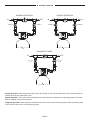
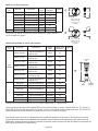
NORMAL OPERATION BYPASS OPERATION
DIAGNOSTIC MODE
IN OUT IN OUT
IN OUT
INLET VALVE
OPEN
OUTLET VALVE
OPEN
BYPASS VALVE
CLOSED
INLET VALVE
CLOSED
OUTLET VALVE
CLOSED
BYPASS VALVE
OPEN
INLET VALVE
OPEN
OUTLET VALVE
CLOSED
BYPASS VALVE
OPEN
Click to buy NOW!
P
D
F
-
X
C
H
A
N
G
E
w
w
w
.
d
o
c
u
-
t
r
a
c
k
.
c
o
m
Click to buy NOW!
P
D
F
-
X
C
H
A
N
G
E
w
w
w
.
d
o
c
u
-
t
r
a
c
k
.
c
o
m

PAGE 5
NORMAL OPERATION BYPASS OPERATION
DIAGNOSTIC MODE
IN OUT IN OUT
IN OUT
INLET VALVE
OPEN
OUTLET VALVE
OPEN
BYPASS VALVE
CLOSED
INLET VALVE
CLOSED
OUTLET VALVE
CLOSED
BYPASS VALVE
OPEN
INLET VALVE
OPEN
OUTLET VALVE
CLOSED
BYPASS VALVE
OPEN
Click to buy NOW!
P
D
F
-
X
C
H
A
N
G
E
w
w
w
.
d
o
c
u
-
t
r
a
c
k
.
c
o
m
Click to buy NOW!
P
D
F
-
X
C
H
A
N
G
E
w
w
w
.
d
o
c
u
-
t
r
a
c
k
.
c
o
m
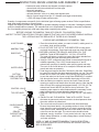
BYPASS VALVE
Normal Operation: Water ows through the control valve during service and also allows the control valve to isolate the
media bed during the regeneration cycle.
Bypass Operation: The control valve is isolated from the water pressure contained in the plumbing system. Untreated
water is supplied to the plumbing system.
Diagnostic Operation: Water pressure is allowed to the control valve and the plumbing system while not allowing water
to exit from the control valve to the plumbing system.

PAGE 6
(All electrical & plumbing should be done in accordance to all local codes)
1. LOCATION: Place the softener where you want to install it, making sure it is on a clean, level and rm surface. The
plug-in power adaptor is for dry locations only. Use an uninterrupted electrical outlet installed within 15 feet of the softener.
Locate the softener so the distance between the drain and the softener is as short as possible. Brine tank should be easily
accessible. Do not install the softener with less than 10 feet of piping between its outlet and the inlet of a water heater.
Do not locate the softener where it or its connections (including the drain and overow lines) will ever be subject to room
temperatures under 40°F.
2. INLET/OUTLET: Connect to a supply line downstream of outdoor spigots. Install an inlet shuto valve and plumb to the
unit’s inlet located at the left front as you face the unit. Installation of a bypass valve is recommended. If using plastic ttings
ground the water conditioner per local electric codes. If a water meter is used, install the water meter on the outlet side of
the control valve. It is recommended that the meter assembly be installed horizontally or in a downow vertical position
to reduce turbine bearing wear. The turbine assembly may be oriented in any direction, but is usually oriented pointing up
to reduce drainage out of the pipes during service. Remove the cover and drive bracket and thread the water meter cord
through the hole in the back plate. Reinstall the drive bracket. Weave the cord through the hooks on the right hand side of
the drive bracket and connect the end to the three prong connector labeled METER on the printed circuit board. Replace
the cover.
3. A jumper ground wire should be installed between the inlet and outlet pipe whenever the metallic continuity of a
water distribution piping system is interrupted. Install grounding strap on metal pipes.
4. DRAIN: The drain must be able to handle the backwash rate of the softener. Correctly size the drain line for the softeners
drain line ow control gpm rating. An adapter tting is supplied with the valve that can connect a 3/4” tting to be used with
drain line ow controls up to 10 gpm, a 1” tting to be used with drain line ow controls up to 25 gpm, or a 1-1/2” tting to be
used with drain line ow controls up to 50 gpm. If soldering, joints near the drain must be done prior to connecting the drain
line ow control tting. Leave at least 6” between the drain line control tting and solder joints when soldering pipes that are
connected on the drain line control tting. Failure to do this could cause interior damage to the drain line ow control tting.
Avoid elevating the drain line above the control valve where possible. Never insert a drain line directly into a drain, sewer
line, or trap. Always allow an air gap between the drain line and the wastewater receptacle to prevent the possibility
of sewage being back-siphoned into the softener.
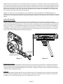
5. REGENERATION: The brine rell ow control assembly is installed in an easy to access rell elbow located on the control
valve. The LX15 series rell ow control assembly is attached to the 1.5” control valve with a locking clip. The locking clip
allows the elbow to rotate 270 degrees so the outlet can be oriented towards the brine tank. The LX2 and LX2QC series
rell ow control assembly is attached to the 2” control valve with a V3151 nut. Connect the brine line polytubing found with
the brine tank to the brine connection on the control valve. The 1.5” control valve has a standard rell elbow to which a 1/2”
exible tube can be connected, see below. One polytube insert is shipped on the brine line elbow’s locking clip. Remove
this white polytube insert and replace the locking clip. The second polytube insert is taped to the top of the brine well cap in
the brine tank. Press the polytube inserts into each end of the provided brine tubing, press the polytube with insert into the
nut on the brine tting. Tighten nut securely to create a pressure tight connection. The nut, gripper and retainer sleeve is a
three-piece assembly that can come apart from the elbow body. Parts must be reassembled exactly as shown to function
properly. If the nut is completely removed from the body, slip the nut, plastic gripper and retainer sleeve on to the tube then
tighten on to the tting.
Note that 1/2” O. D. brine tube runs longer than 6 feet may restrict draw rates for LX15 series softeners using 21” or
larger diameter mineral tanks. Locate brine tank as close as possible to softener. Increase brine tubing size to 5/8”
O. D. if necessary. Make sure the oor is clean beneath the brine tank and that it is level and smooth. Install brine tubing
to the brine tank using the above instructions. The LX2 and LX2QC Series 2” control valves have a 1” PVC rell elbow
connection (tting kits available for 1/2” and 5/8” O. D. tubing connections); use 1” pipe to connect brine tank to
2” control valves for 30” or larger diameter mineral tanks.
6. OVERFLOW: A 1/2” (inside diameter, not provided) gravity drain line should be connected to the overow tting on
the side of the brine tank. This overow is in case of a malfunction in the brine shut o. If the unit is installed where water
may ow in the event of an overow and cause water damage, connect a length of exible tubing and run to a drain below
the level of the overow. (Do not connect the tubing to the drain line on the control valve. Do not run tubing above
overow height at any point. Provide air gap.)
INSTALLATION INSTRUCTIONS
BRINE LINE FITTING CONNECTIONS
DRAIN LINE FITTING CONNECTION USING 5/8" POLY TUBE
Click to buy NOW!
P
D
F
-
X
C
H
A
N
G
E
w
w
w
.
d
o
c
u
-
t
r
a
c
k
.
c
o
m
Click to buy NOW!
P
D
F
-
X
C
H
A
N
G
E
w
w
w
.
d
o
c
u
-
t
r
a
c
k
.
c
o
m

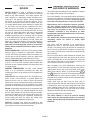
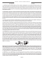
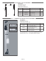
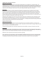
PAGE 7
1.93
1.86
.99
Outlet
1 1/2 Thread
Inlet
1 1/2 Thread
TOT
C
L
Injector
4-8 UN
3.25
6.44
8.60
.03
1.50
Regenerant
Drain Port
1 1/4 NPT
Drain Flow
Control
3.25
.61
Series LX15
LXCV15 Control Valve
.62
.27
2.14
4.00 4.50
Outlet
2" Threads
Inlet
2" Threads
Drain Port 1 1/2 NPT
Units Are Shipped
Without A DLFC Installed
Injector
Regenerant
Line
TOT
C
L
3.50
3.50
9.02 7.85
Drain Port
1 1/2 NPT
Drain Flow
Control
Regenerant
Series LX2
LXCV2 Control Valve
Specic model
overall dimensions
are available-
Consult factory.
Specic model
overall dimensions
are available-
Consult factory.
Note: Series LX2QC uses
LXCV2QC Quick Connect
control valve (not shown).
Dimensions are available-
Consult factory.

PAGE 8
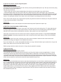
IN OUT
BYPASS VALVE
TO
DRAIN
DRAIN LINE
AIR GAP
ADAPTER
METER
AIR GAP
OR
TO
FLOOR
DRAIN
LOCATE WATER SOFTENER
AS CLOSE AS POSSIBLE
TO BRINE TANK.
BRINE TANK WATER SOFTENER
INLET
VALVE
OUTLET
VALVE
LOCATE WATER SOFTENER
CLOSE TO A DRAIN.
AVOID OVERHEAD DRAIN
LINES IF POSSIBLE.
READ INSTALLATION
INSTRUCTIONS.
READ INSTALLATION
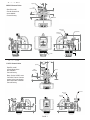
OVERFLOW GRAVITY DRAIN - ONLY USED IN CASE OF MALFUNCTION IN THE BRINE SHUTOFF.
DO NOT CONNECT TO CONTROL VALVE DRAIN LINE.
IF UNIT IS INSTALLED WHERE OVERFLOW COULD CAUSE WATER DAMAGE, CONNECT TUBING
AND RUN TO FLOOR DRAIN.
DO NOT RUN TUBING ABOVE OVERFLOW HEIGHT.
READ INSTALLATION INSTRUCTIONS.
INSTRUCTIONS.
SINGLE: ONE WATER SOFTENER WITH METER, ONE BRINE TANK.
REGENERATION INITIATION CHOICES: METER IMMEDIATE, METER DELAYED, METER DELAYED + IMMEDIATE,
DAYS OVERRIDE (1-28), AUXILIARY INPUT (SEE CUSTOM PROGRAMMING AND APPLICATION MANUAL).
READ
INSTALLATION
INSTRUCTIONS
REGARDING
METER
CONNECTION
FLEXIBLE CONNECTORS
ARE RECOMMENDED
BETWEEN
WATER SOFTENER
AND
SYSTEM HARD PIPING.
UNION TYPE CONNECTORS
ARE RECOMMENDED
ON THE INLET AND OUTLET
CONNECTIONS.
Click to buy NOW!
P
D
F
-
X
C
H
A
N
G
E
w
w
w
.
d
o
c
u
-
t
r
a
c
k
.
c
o
m
Click to buy NOW!
P
D
F
-
X
C
H
A
N
G
E
w
w
w
.
d
o
c
u
-
t
r
a
c
k
.
c
o
m
TOP VIEW
WITH OPTIONAL NO HARD
WATER BYPASS VALVE SHOWN
METER
OPTIONAL NO HARD WATER BYPASS VALVE (NHBP)
CAN BE INSTALLED BEFORE METER AS SHOWN OR
AFTER METER (SEE NEXT PAGE)

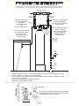
PAGE 9
IN
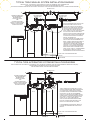
TYPICAL TWIN PARALLEL SYSTEM INSTALLATION DIAGRAM
TWIN PARALLEL: TWO IDENTICAL SOFTENERS, EACH WITH ITS OWN METER, ONLY ONE BRINE TANK.
METER DELAYED REGENERATION USED WITH OFFSET REGENERATION TIMES.
BOTH WATER SOFTENERS ARE ONLINE FOR DOUBLE THE SERVICE FLOW RATE AND EXCHANGE CAPACITY OF A SINGLE WATER SOFTENER.
OUT
BYPASS VALVE
OPTIONAL
NO HARD WATER
BYPASS VALVE
OPTIONAL
NO HARD WATER
BYPASS VALVE
METERMETER
FLOOR DRAIN
AIR GAP
DO NOT TEE TOGETHER DRAIN LINES
OPTIONAL NHBP:
ROUTE THE NHBP MOTOR CABLE TO THE
WATER SOFTENER CONTROL VALVE.
FACING THE CONTROL VALVE KEYPAD
AND DISPLAY, REMOVE THE COVER AND
LOCATE THE CIRCULAR KNOCKOUT ON
THE LOWER LEFT SIDE OF THE BACK-
PLATE. PUNCH OUT THE CIRCULAR KNOCK-
OUT PIECE WITH MILD FORCE USING A
PUNCH OR PHILLIPS-HEAD SCREW DRIVER.
REFER TO MAV INSTALLATION GUIDE FOR
UTILIZING STRAIN RELIEF ON THE BACK-
SIDE OF THE BACKPLATE.
IN
TYPICAL TWIN ALTERNATOR SYSTEM INSTALLATION DIAGRAM
TWIN ALTERNATING: TWO IDENTICAL SOFTENERS, ONLY ONE METER AND BRINE TANK, AND ONE MOTORIZED ALTERNATING VALVE (MAV).
METER IMMEDIATE REGENERATION WITH HARD WATER USED.
ONE SOFTENER ONLINE, ONE SOFTENER ON STANDBY.
OUT
BYPASS VALVE
FLOOR DRAIN
AIR GAP
DO NOT TEE TOGETHER DRAIN LINES
A B
C
METER
SYSTEMS ORDERED WITH NHBP OPTION
ARE FACTORY PRE-PROGRAMMED FOR
NHBP. CONNECT NHBP MOTOR CABLE TO
THE PC BOARD TWO PIN CONNECTOR
LABELED MAV MTR BEFORE PLUGGING IN
CONTROL VALVE. A NHBP PROGRAMMED
CONTROL VALVE MUST RECOGNIZE THE
NHBP CONNECTION OTHERWISE ERROR
CODE 106 WILL DISPLAY. IF PROGRAMMING
IS NECESSARY, REFER TO CUSTOM
PROGRAMMING AND APPLICATION MANUAL.
ALT A ALT B
"A"
PORT
"B"
PORT
"C"
PORT
MAV
MAV
MOTOR
CABLE
3-WIRE
INTER-
CONNECT
CABLE
METER
CABLE TWIN ALTERNATOR SYSTEMS ARE FACTORY
PRE-PROGRAMMED AND LABELED. MAKE SURE
ALL CABLES ARE CONNECTED TO PROPER
PC BOARD CONNECTIONS BEFORE PLUGGING
IN CONTROL VALVES. MAV PROGRAMMED
CONTROL VALVES MUST RECOGNIZE THE MAV
CONNECTIONS OTHERWISE ERROR CODE 106
WILL DISPLAY. REFER TO MAV INSTALLATION
GUIDE FOR 1.5" AND 2" SINGLE METER
APPLICATIONS REGARDING PROPER CABLE
IF PROGRAMMING IS NECESSARY, REFER TO
CUSTOM PROGRAMMING AND APPLICATION
MANUAL.
ROUTING, CONNECTIONS AND USE OF THE
BACKPLATE STRAIN RELIEF FOR CABLE.
FLEXIBLE CONNECTORS
ARE RECOMMENDED
BETWEEN EACH
WATER SOFTENER
AND
SYSTEM HARD PIPING
(REFER TO SINGLE SYSTEM
INSTALLATION DIAGRAM
ON PREVIOUS PAGE)
FLEXIBLE CONNECTORS
ARE RECOMMENDED
BETWEEN EACH
WATER SOFTENER
AND
SYSTEM HARD PIPING
(REFER TO SINGLE SYSTEM
INSTALLATION DIAGRAM
ON PREVIOUS PAGE)
Click to buy NOW!
P
D
F
-
X
C
H
A
N
G
E
w
w
w
.
d
o
c
u
-
t
r
a
c
k
.
c
o
m
Click to buy NOW!
P
D
F
-
X
C
H
A
N
G
E
w
w
w
.
d
o
c
u
-
t
r
a
c
k
.
c
o
m

PAGE 10
Do not add salt to the brine tank yet. Do not plug the transformer into the receptacle yet. Make sure inlet and outlet valves
are to their closed positions. If using optional bypass, open bypass valve. Turn on main water supply. Open a cold water
faucet. This will clear the line of any debris (solder, pipe dope, etc.) that may be in the line. Let water run at faucet for a
couple minutes, or until clear. Turn o faucet. Manually pour enough water into the brine tank to reach the top of the air
check valve located at the bottom of the brine valve assembly in the white brine well. Now plug the transformer into a 120
volt receptacle (be certain the receptacle is uninterrupted). Within 5 seconds the control display and buttons will illuminate
and the time of day screen will appear.
• Press and hold the REGEN button for approximately 5 seconds until the motor starts.
• Wait until display reads BACKWASH and numbers start counting down.
• Momentarily press REGEN again. Valve is now in the REGENERANT DRAW position.
• Momentarily press REGEN again. Valve is now in the second BACKWASH position.
SLOWLY open inlet valve to DIAGNOSTIC mode (See page 5) to allow water to slowly ll Softener and expel air.
CAUTION: If water ows too rapidly, there could be a loss of resin out of the drain.
When water is owing steadily to drain without the presence of air, momentarily press REGEN again. Display will read
RINSE. Close the bypass valve and open the outlet valve of the softener, for NORMAL OPERATION (see page 5). Allow
control to nish the RINSE cycle. It will then advance to the FILL position. The brine tank will now automatically ll with the
proper volume of water for the rst regeneration. Allow the control to automatically advance to the SOFTENING position.
Now load the brine tank with salt. Solar Salt is recommended. The brine tank salt level should be checked every couple of
weeks to determine salt usage. Keeping the brine tank salt level at least 1/2 full is recommended.
SANITIZING: Use 2 oz. of 5 ¼% unscented household chlorine bleach for each cubic foot of resin. Pour bleach directly
into the white brine well located inside the brine tank. Press and hold the REGEN for 5 - 6 seconds until the motor starts
running. Allow system to complete the regeneration automatically. Check for other local and state codes which may also
specify sanitation methods.
PLACING SOFTENER INTO SERVICE
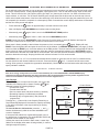
GENERAL OPERATION
User Displays
When the system is in normal service mode, one of up to ve
available User Displays will be shown. Pressing NEXT will
alternate between the following displays:
• Current time of day
• Treated water ow rate
• Service contact name and phone number (if entered)
• Remaining Capacity of treated water available
• Remaining days to regeneration (if Day Override is
programmed)
Pressing the button while in the Capacity Remaining or
Days Remaining displays will decrease the capacity remaining
in ten gallon increments or the days remaining in one day
increments.
To clear the Service Call reminder, press the and
buttons simultaneously while the number and banner text
screen is displayed.
If the system has called for a regeneration that will occur at
the preset time of regeneration, the words REGEN TODAY will
alternate with the header on the display.
Utilizing the control valve’s built-in water meter, a water drop
ashes on the display when water is being treated (i.e. water is
owing through the system).
Drop will ash while water
is being treated.
NEXT
NEXT
NEXT
Contact Screen
NEXT
Note: As an energy saving feature, the control will automatically turn o all SOLID BLUE or SOLID GREEN display
illumination and keypad illumination after about 5 minutes of the last keypad button push. Any further keypad touch will
cause the re-illumination of the display and keypad, and re-activate keypad control.

PAGE 11
Current time of day needs to be entered during initial installation, and adjusted when daylight saving time begins or ends.
If an extended power outage occurs and depletes the on-board non-rechargeable coin cell battery, when power resumes
the time of day should be reset and battery replaced.
STEP 1
STEP 2
STEP 3
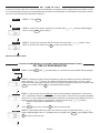
STEP 1 – Press CLOCK
STEP 2 - Current Time (hour): Set the hour of the day using or buttons. AM/PM toggles
after 12. Press NEXT to go to Step 3.
STEP 3 - Current Time (minutes): Set the minutes of the day using or buttons. Press
NEXT to exit Set Time of Day. Press REGEN to return to previous step.
RETURN TO NORMAL MODE
SET TIME OF DAY
ADJUST HARDNESS, DAYS BETWEEN REGENERATIONS,
OR TIME OF REGENERATION
STEP 1
STEP 2
STEP 4
STEP 1 - Press NEXT and simultaneously for 3 seconds to access Installer Display Settings.
STEP 2 – Hardness: Set the amount of hardness in grains of hardness as calcium carbonate per
gallon using the or buttons. The default is 20 with value ranges from 1 to 150 in 1 grain
increments. Note: The grains per gallon can be increased if soluble iron needs to be reduced. Press
NEXT to go to step 3. Press REGEN to exit Installer Display Settings.
STEP 3 – Day Override: Set the maximum number of days between regenerations. If value set to
“OFF”, regeneration initiation is based solely on volume used. If value is set as a number (allowable
range from 1 to 28) a regeneration initiation will be called for on that day even if sucient volume of
water were not used to call for a regeneration. Set Day Override using or buttons:
• number of days between regeneration (1 to 28); or
• “OFF”.
Press NEXT to go to step 4. Press REGEN to return to previous step.
STEP 4 – Next Regeneration Time (hour): Set the hour of day for regeneration using or
buttons. AM/PM toggles after 12. The default time is 2:00 AM. Press NEXT to go to Step 5. Press
REGEN to return to previous step.
STEP 3

PAGE 12
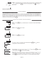
STEP 5 STEP 5 – Next Regeneration Time (minutes): Set the minutes of day for regeneration using
or buttons. Press NEXT to return to normal operation. Press REGEN to return to
previous step.
RETURN TO NORMAL MODE
CONTACT SCREEN PROGRAMMING
STEP 1 - Press NEXT and simultaneously for 3 seconds to access Installer Display
Settings.
STEP 2 - Press NEXT to go to step 3.
STEP 3 - Press NEXT to go to step 4.
From Step 4, while hour is ashing, press and hold both the CLOCK and button to
change phone number and banner text.
Phone Number - Set phone number using the or arrow. Press NEXT to forward
to the next digit. Press REGEN to return to previous digit.
Banner Text - Set the banner text up to a maximum of 44 characters. Use the or
to select letters of the alphabet, numbers, ampersand (&), or a space in the banner text.
Press NEXT to forward to the next character or to exit the Installer Display Settings.
STEP 1
STEP 2
STEP 3
STEP 4
A non-rechargeable coin cell battery is located on the circuit board, used only to maintain the time of day during power
outages (all other information will be stored in memory no matter how long the power outage). The screen displays LOW
BATTERY when the battery needs to be replaced. The screen will remain illuminated solid blue when LOW BATTERY is
displayed. Initially LOW BATTERY display will alternate with the User display, nally displaying only LOW BATTERY. User
displays are still accessible by pressing NEXT .
LOW BATTERY

PAGE 13
X FACTOR COMMERCIAL SERIES
GENERAL SPECIFICATIONS
Operating Pressure;
Min to Max (PSI) 20 to 125
CAUTION: the softener cannot be subject to a vacuum due to loss of pressure (such as a water main break or
submersible well pump check valve failure).
Water Operating Temp;
Min to Max (°F) 40 to 110
CAUTION: do not locate the softener where it or its connections (including the drain line and overow lines) will ever be
subject to room temperatures under 40°F
AC Adaptor Input;
Voltage - Hertz 120V AC - 60 Hz
AC Adaptor Output;
Voltage - Current 12V AC - 500 mA
3 Volt Lithium Coin Cell
Battery; type 2032
PC Board Relay
Terminal Block DC
Output; Voltage
12V DC **
** Relay Specications: 12V DC Relay with a coil resistance not less than 80 ohms. If mounting the relay under the con-
trol valve cover, check for proper mounting location dimensions on the backplate.
No user serviceable parts are on the PC board, motor, or the Power adapter. The means of disconnection from the main
power supply is by unplugging the Power adapter from the wall.
Control Valve;
Inlet/Outlet/ Drain Port NPT size See page 7
Meter Accuracy ± 5%
Meter Flow Range 1.5”: 0.5-75 gpm, 2”: 1.5-150 gpm
Compatible with the following
typical concentrations of regenerants Sodium chloride, potassium chloride
SPECIFIC MODEL # SPECIFICATIONS ARE AVAILABLE. PLEASE CONSULT FACTORY.
CONTROL VALVE
METER
TOP DIFFUSER
MINERAL TANK
RISER PIPE
ION EXCHANGE
RESIN
SUPPORT BED
#20 FLINT
BOTTOM
HUB & LATERAL
DISTRIBUTOR
NOTE-
14" AND 16" DIAMETER
MINERAL TANKS ARE
BOTTOM VORTECH
DISTRIBUTOR PLATE
DESIGN; NO SUPPORT
BED IS REQUIRED.
CONTROL VALVE, METER AND BRINE VALVE ASSEMBLY PARTS DIAGRAMS ON NEXT PAGES.
BRINE
POLYTUBING
BRINE TANK
WITH
COVER
2-PIECE
OVERFLOW
FITTING
BRINE WELL
BRINE WELL
CAP
BRINE VALVE ASSEMBLY
Click to buy NOW!
P
D
F
-
X
C
H
A
N
G
E
w
w
w
.
d
o
c
u
-
t
r
a
c
k
.
c
o
m
Click to buy NOW!
P
D
F
-
X
C
H
A
N
G
E
w
w
w
.
d
o
c
u
-
t
r
a
c
k
.
c
o
m

PAGE 14
1
3
4
2
Click to buy NOW!
P
D
F
-
X
C
H
A
N
G
E
w
w
w
.
d
o
c
u
-
t
r
a
c
k
.
c
o
m
Click to buy NOW!
P
D
F
-
X
C
H
A
N
G
E
w
w
w
.
d
o
c
u
-
t
r
a
c
k
.
c
o
m
FOR MODELS
LX15-90 thru LX15-300
LX2-120 thru LX2-300
LX2QC-120 thru LX2QC-300
Drawing No. Order No. Description Quantity
1 H4600 with H4650 Safety Brine Valve with
½” Elbow & Polytube Insert 1
2 10151 Pin 1
3 H4640-9.5 Float Assembly 1
4 H4500-48 Air Check Assembly (uncut
length) ½” x 48” 1
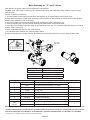
4740 BRINE VALVE ASSEMBLY
494 1” COMMERCIAL BRINE VALVE ASSEMBLY
494 1" Commercial
Brine Valve
U.S. and Foreign Patents Pending
Built from a revolutionary new design the 494 1" commercial brine valve
delivers on today’s demand for simplicity and higher brine draw and rell
rates. The 494's "top of brine tank" design allows for easy access and
serviceability as well as brine draw rates up to 20 gpm and rell rates up
to 10 gpm.
The patent pending design features an “over-center” check disc to
prevent prechecking during brine rell, when air in the brine line could
cause excessive ow rates.
The 494 brine valve also features a new adjustable oat design, which
allows the oat to be adjusted with a simple twist of the locking nut.
The 494 assembly (H4900) includes the brine valve, two brine
connection elbows, adjustable oat, air check assembly with 60" riser,
1" riser adapter and oat rod guide.
Maximum Operating Pressure: 125 psig (862 kPa) • Temperature Range: 40-110°F (4-43°C)
PRODUCT FEATURES
• High ow rates in both rell and draw position
• Plastic valve and air check
• Brine Valve molded from composite plastics to ensure strength
and durability
• Easily adjustable oat design with locking nut
• Easy access to check disk for serviceability
• Two Brine elbows included (1" PVC male and ¾" x 1" PVC solvent)
Order No. Description Qty/Ctn
H4900 494 1” BRINE VALVE, FLOAT ASSEMBLY, AIR CHECK
AND 60" RISER (AS SHOWN IN PICTURE)
1
H4940 494 1” BRINE VALVE AND FLOAT ASSEMBLY ONLY
(LESS RISER AND AIR CHECK)
1
H4950 494 1" AIR CHECK (LESS RISER) 1
H4950-48 494 1” AIR CHECK WITH RISER (48" LENGTH) 6
H4950-60 494 1” AIR CHECK WITH RISER (60" LENGTH) 6
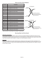
ORDER INFORMATION
Order No. H4900
Order No. H4915
Order No. H4916
Rell Flow Rate
Pressure Drop (psig)
Rell Flow Rate (gpm)
10
8
6
4
2
0
0 1 2 3 4 5
Brine Draw Rate
Vacuum (In. of Hg)
Brine Draw Rate (gpm)
20
15
10
5
0
0 5 10 15 20
FOR MODELS
LX2-450 thru LX2-1200
LX2QC-450 thru LX2QC-1200
Order No. Description Quantity
H4900 494 1” Brine Valve, Float Assembly,
Air Check, and 60” Riser 1
H4915 Fitting Kit 494 Brine Valve ½”
Polytube Connection 1
H4916 Fitting Kit 494 Brine Valve ⅝”
Polytube Connection 1
H4900 includes the brine valve, two brine connection elbows (1”
PVC male NPT and ¾ x 1” PVC solvent) adjustable oat, air check
assembly with 60” riser, 1” riser adapter and oat rod guide.

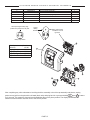
PAGE 15
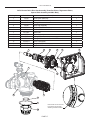
Drawing No. Order No. Description Quantity
1V3692-02LW LP Front Cover Assembly 1
2 V3107-01 Motor 1
3 V3106-01 Drive Bracket & Spring Clip 1
4 V3757LP-BOARD PC Board 1
5 V3110 Drive Gear 12x36 3
6 V3109 Drive Gear Cover 1
AC Adapter
Order No.
(Not shown)
V3186
Supply Voltage 120V AC
Supply Frequency 60 Hz
Output Voltage 12V AC
Output Current 500 mA
Battery Fully Seated
When replacing the battery, align
positives and push down to fully seat. Battery replacement is
3 volt lithium coin cell
type 2032.
Correct
Battery
Orientation
1
23
5
6
4
X-FACTOR FRONT COVER AND DRIVE ASSEMBLY
After completing any valve maintenance involving the drive assembly or the drive cap assembly and pistons, unplug
power source jack from the printed circuit board (black wire) and plug back in or press and hold NEXT and REGEN buttons
for 3 seconds. This resets the electronics and establishes the service piston position. The display should ash the
software version and then reset the valve to the service position.

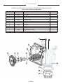
PAGE 16
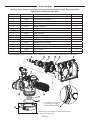
LXCV15 Control Valve Drive Cap Assembly, Downow Piston, Regenerant Piston,
Spacer Stack Assembly and Main Body
Drawing No. Order No. Description Quantity
1 V3004 Drive Cap Assembly 1
2 V3135 O-ring 228 1
3 V3407 Piston Downow Assembly 1
4 V3174 Regenerant Piston 1
5 V3423 Backplate Dowel 1
6 V3430 Spacer Stack Assembly 1
7 V3178LP Back Plate 1
8 V3419 O-ring 347 1
9 V3641 O-ring 225 for valve bodies with NPT threads 1
10 V3950-01 1.5 NPT Valve Body, Gen 2 1
11 V3468 Test Port Plug, 1/4” NPT 2
12 D1300 Top Bae Diuser, 1.5/50MM 1
LX15 SERIES
12
5
431
11
10
9
2
8
6
7

PAGE 17
LX2 SERIES
LXCV2 Control Valve Drive Cap Assembly, Downow Piston, Regenerant Piston,
Spacer Stack Assembly and Main Body
Drawing No. Order No. Description Quantity
1 V3726 Brine Piston Assembly 1
2 V3725 Piston Downow Assembly 1
3 V3452 O-ring 230 1
4 V3728 Drive Cap Assembly 1
5 V3724 Washer Flat SS 1/4 4
6 V3642 Bolt BHCS S/S 1/4-20X1.25 4
7 V3178LP Back Plate 1
8 V3729 Stack Assembly 1
9 V3419 O-ring 347 1
10 V3641 O-ring 225 for valve bodies with NPT threads 1
11 V3700-01 2 NPT Valve Body 1
12 V3468 Plug, 1/4” NPT 2
13 D1300 Top Bae Diuser, 1.5/50MM 1
A
A
1
13
9
10
11 8
7543
6
2
12
Drive bracket can be removed
by squeezing (2) lock tabs
& rotating counter clockwise.

PAGE 18
LX2QC SERIES
LXCV2QC Quick Connect Control Valve Drive Cap Assembly, Downow Piston, Regenerant Piston,
Spacer Stack Assembly and Main Body
Drawing No. Order No. Description Quantity
1 V3726 Brine Piston Assembly 1
2 V3725 Piston Downow Assembly 1
3 V3452 O-ring 230 1
4 V3728 Drive Cap Assembly 1
5 V3724 Washer Flat SS 1/4 4
6 V3642 Bolt BHCS S/S 1/4-20X1.25 4
7 V3178LP Back Plate 1
8 V3729 Stack Assembly 1
9 V3279 O-ring 346 1
10 V3280 O-ring 332 for valve bodies with NPT threads 1
11 V3737-01 2 NPT QC Valve Body 1
12 V3054* 4IN Base Clamp Assembly 1
13 V3276 Bolt Hex 5/16 - 18 x 1-3/4 1
14 V3269 Nut 5/16 - 18 SS Hex 1
15 V3468 Plug, 1/4” NPT 2
Not Shown D1300-01 Top Bae Diuser, 2/63MM 1
* V3054 4IN Base Clamp Asy includes a V3276 Bolt Hex 5/16 - 18 X 1-3/4 and V3269 Nut 5/16 - 18 SS Hex
A
Drive bracket can be removed
by squeezing (2) lock tabs
& rotating counter clockwise.
Install D1300-01 upper diuser (not shown) when using the
4” Quick Disconnect (V3064).
1
9
10
11 8
7543
6
2
15
12
14
13

PAGE 19
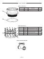
LX2QC SERIES
V3064 4 Inch Base Asy
Drawing No. Order No. Description Quantity
1 V3202-01 Base 1
2 V3281 O-Ring 348 1
V3055 Flange Base Asy
Drawing No. Order No. Description Quantity
1 V3444 Screw Hexcap 5/16-18 x 2 SS 12
2 V3293 Washer SS 5/16 Flat 24
3 V3445 Washer Split Lock 5/16 SS 12
4 V3447 Nut Hex 5/16-18 Full SS 12
5 COR60FL O Ring 6 Flange Adapter (Park) 1
6 V3261-01 Flange Base 1
V3260-02 Side Mount Base NPT
2
1
3
6
5
1
2
4

PAGE 20
LX15 SERIES
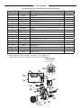
LXCV15 Injector Valve Body, Rell Flow Control and Injector
Drawing No. Order No. Description Quantity
1 V3967 Injector Body, Welded Assembly 1
2 V3441 O-ring -226 1
3 V3968*** Injector Feed Tube 1
4 V3177-01 Injector Screen 1
5 V3969**** Injector Draw Tube 1
6 V4349 Injector Cap (V3176 on valves prior to 4./5/2020) 1
7 V3152 O-ring -135 1
8 See page 22 Injector 1
9 V3498** Rell Flow Control, 1/2” 1
10 V3428** Rell Retainer Assembly (0.5 GPM) 1
11 V3163 O-ring, -019 1
12 H4612 Regenerant Elbow w/Flow Control 1
13 JCPG-8PBLK Nut, Compression, 1/2” Black 1
14 JCP-P-8 Insert, Polytube 1/2” 1
15 V3182 Rell Flow Control (0.5 GPM) 1
16 H4615 Retaining Clip 1
17 V3724 Washer, Flat Stainless Steel 4
18 V3642 Bolt, BHCS Stainless Steel 1/4-20x 1 1/4 4
19 V3195-01 Rell Port Plug 1
** Contains a V3182 0.5 gpm ow control
*** V3968 contains one D1240 O-RING 111 and two V3155 O-RING 112
**** V3969 contains one V3638 O-RING 113 and two V3157 O-RING 115
3
5
4
2
18
6
71
8
16
12
19
17
9
14
13
10
11
15
Proper RFC orientation
directs rell water ow
toward the washer face
with radius and text
Page is loading ...
Page is loading ...
Page is loading ...
Page is loading ...
Page is loading ...
Page is loading ...
Page is loading ...
Page is loading ...
Page is loading ...
Page is loading ...
Page is loading ...
Page is loading ...
Page is loading ...
Page is loading ...
Page is loading ...
Page is loading ...
-
 1
1
-
 2
2
-
 3
3
-
 4
4
-
 5
5
-
 6
6
-
 7
7
-
 8
8
-
 9
9
-
 10
10
-
 11
11
-
 12
12
-
 13
13
-
 14
14
-
 15
15
-
 16
16
-
 17
17
-
 18
18
-
 19
19
-
 20
20
-
 21
21
-
 22
22
-
 23
23
-
 24
24
-
 25
25
-
 26
26
-
 27
27
-
 28
28
-
 29
29
-
 30
30
-
 31
31
-
 32
32
-
 33
33
-
 34
34
-
 35
35
-
 36
36


Lancaster LX15 Series Installation, Operating And Service Manual
- Type
- Installation, Operating And Service Manual
- This manual is also suitable for
Ask a question and I''ll find the answer in the document
Finding information in a document is now easier with AI
Related papers


Other documents
-
 Excalibur Water Systems CHLOROSOFT SERIES Installation guide
-
 Tahoe T../MA-BTB series Installer Manual
-
Culligan ISP2-1044 Owner's manual
-
 GUTHRIE & FREY GF40 Installation, Operation and Maintenance Manual
-
Watts PWSRTA Installation guide
-
 NOVO NovoSoft 165 Series Operating instructions
-
 ProFlow Fleck ProFloSE DF Owner's manual
-
Hydrotech Fleck FAF 2750 Owner's manual
-
CMP Del Ozone Spa Check Valve Owner's manual
-
 Water Right Sanitizer Plus ASP2-1044 Installation Instructions & Owner's Manual


