77-3118-R3 (9/2018) 1 / 8 www.carlisleft.com
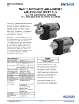
SPECIFICATIONS
Maximum air inlet pressure: 7 bar [105 psi]
Air requirements (operating pressure): 4.8-6.9 bar [70-100 psi]
Air inlet ports (1x per valve): 1/8" NPT (f)
Maximum fluid pressure: 20.7 bar [300 psi]
Fluid inlet ports (2x per valve): 1/4" NPT (f)
Fluid outlet connection: 1/4" NPT (f)
Fluid flow capacity: 3800 cc/min @ 47 psi pressure drop
(paint viscosity = 700 centipoise)
Varies according to material pressure and viscosity.
Valve actuation speed (ON/OFF cycles): 55 cycles/min
Maximum number of colors: 30
Wetted parts: 300 series Stainless Steel, PTFE
EN
SERVICE MANUAL
240-5100 COLOR CHANGE VALVE STACKS
LOW PRESSURE

EN
77-3118-R3 (9/2018)2 / 8www.carlisleft.com
DE-ENERGIZE, DEPRESSURIZE, DISCONNECT AND LOCK
OUT ALL POWER SOURCES DURING MAINTENANCE
Failure to De-energize, disconnect and lock out all power supplies
before performing equipment maintenance could cause serious
injury or death.
OPERATOR TRAINING
All personnel must be trained before operating finishing
equipment.
EQUIPMENT MISUSE HAZARD
Equipment misuse can cause the equipment to rupture,
malfunction, or start unexpectedly and result in serious injury.
PROJECTILE HAZARD
You may be injured by venting liquids or gases that are released
under pressure, or flying debris.
PINCH POINT HAZARD
Moving parts can crush and cut. Pinch points are basically any
areas where there are moving parts.
INSPECT THE EQUIPMENT DAILY
Inspect the equipment for worn or broken parts on a daily basis.
Do not operate the equipment if you are uncertain about its
condition.
In this part sheet, the words WARNING, CAUTION and NOTE are used to
emphasize important safety information as follows:
Hazards or unsafe practices which
could result in minor personal injury,
product or property damage.
!
CAUTION
Hazards or unsafe practices which
could result in severe personal
injury, death or substantial property
damage.
!
WARNING
Important installation, operation or
maintenance information.
NOTE
Read the following warnings before using this equipment.
READ THE MANUAL
Before operating finishing equipment, read and understand all
safety, operation and maintenance information provided in the
operation manual.
WEAR SAFETY GLASSES
Failure to wear safety glasses with side shields could result in
serious eye injury or blindness.
NEVER MODIFY THE EQUIPMENT
Do not modify the equipment unless the manufacturer provides
written approval.
IT IS THE RESPONSIBILITY OF THE EMPLOYER TO PROVIDE THIS INFORMATION TO THE OPERATOR OF THE EQUIPMENT.
FOR FURTHER SAFETY INFORMATION REGARDING THIS EQUIPMENT, SEE THE GENERAL EQUIPMENT SAFETY BOOKLET (77-5300).
KNOW WHERE AND HOW TO SHUT OFF THE EQUIPMENT
IN CASE OF AN EMERGENCY
HIGH PRESSURE CONSIDERATION
High pressure can cause serious injury. Relieve all pressure before
servicing. Spray from the spray gun, hose leaks, or ruptured
components can inject fluid into your body and cause extremely
serious injury.
NOISE HAZARD
You may be injured by loud noise. Hearing protection may be
required when using this equipment.
STATIC CHARGE
Fluid may develop a static charge that must be dissipated through
proper grounding of the equipment, objects to be sprayed and all
other electrically conductive objects in the dispensing area. Improper
grounding or sparks can cause a hazardous condition and result in
fire, explosion or electric shock and other serious injury.
KEEP EQUIPMENT GUARDS IN PLACE
Do not operate the equipment if the safety devices have been
removed.
!
WARNING
PACEMAKER WARNING
You are in the presence of magnetic fields which may interfere
with the operation of certain pacemakers.
PRESSURE RELIEF PROCEDURE
Always follow the pressure relief procedure in the equipment
instruction manual.
EU Declaration of Conformity
We: Finishing Brands declare that the above product conforms with the Provisions of Machinery Directive 2006/42/
EC and the ATEX Directive 94/9/EC by complying with the following statutory documents and harmonized standards:
Machinery Safety Standards EN ISO 12100
Explosion Prevention Potentially Explosive Atmospheres EN 1127-1
Non-electrical Equipment for Potentially Explosive Atmospheres BS EN 13463-1
Providing all conditions of safe use stated within the product manuals have been complied with and that the
final equipment into which this product is installed has been re-assessed as required, in accordance with essential
health and safety requirements of the above standards, directives and statutory instruments and also installed in
accordance with any applicable local codes of practice.
Chuck McCulloch, Manager – Fluid Handling Research & Development
May 01, 2015
Note: Read and follow all instructions and safety precautions before using this
equipment.
Product Descriptions
240-51xx Color Change Valve Stacks
This product is designed for use with Solvent based and Waterborne materials.
Suitable for use in Zone 1 and 2, Protection Level: II 2 G X
Manufacturer: Finishing Brands
Toledo, OH 43612
AUTOMATIC EQUIPMENT
Automatic equipment may start suddenly without warning.

EN
77-3118-R3 (9/2018) 3 / 8 www.carlisleft.com
240-5100 INSTALLATION
VERTICAL DIMENSION
240-5101
104.8mm [4.125in]240-5102
240-5103
240-5104 139.8mm [5.501in]
240-5105
240-5106 174.7mm [6.877in]
240-5107
240-5108 209.6mm [8.253in]
240-5109
240-5110 244.6mm [9.629in]
240-5111
240-5112 279.5mm [11.005in]
240-5113
240-5114 314.5mm [12.381in]
240-5115
240-5116 349.4mm [13.757in]
240-5117
240-5118 384.4mm [15.133in]
240-5119
240-5120 419.3mm [16.509in]
240-5121
240-5122 454.3mm [17.885in]
240-5123
240-5124 489.2mm [19.261in]
240-5125
240-5126 524.2mm [20.637in]
240-5127
240-5128 559.1mm [22.013in]
240-5129
240-5130 594.1mm [23.389in]
240-5131
SEE
CHART
33mm
1.312in
7mm
.266in
213mm
8.376in
70mm
2.750in
240-5108 SHOWN
Fluid Outlet port:
1/4" NPT (f)
Fluid Inlet port:
1/4" NPT (f)
Air Inlet port:
1/8" NPT (f)

EN
77-3118-R3 (9/2018)4 / 8www.carlisleft.com
240-5100 COLOR CHANGE STACK ASSEMBLIES
1
13
9
3
12
11
8
7
6
5 10
4
2
3
1
1
240-5108
8 VALVE ASSEMBLY SHOWN
ITEMS 1, 5, 6, & 9 QUANTITIES WILL VARY.
SEE PARTS LIST AT RIGHT.

EN
77-3118-R3 (9/2018) 5 / 8 www.carlisleft.com
240-5100 COLOR CHANGE VALVE STACKS
Item
No. Part No. Description
240-5101
240-5102
240-5103
240-5104
240-5105
240-5106
240-5107
240-5108
240-5109
240-5110
240-5111
240-5112
240-5113
240-5114
240-5115
240-5116
240-5117
240-5118
240-5119
240-5120
240-5121
240-5122
240-5123
240-5124
240-5125
240-5126
240-5127
240-5128
240-5129
240-5130
240-5131
1 CCV-503-SS COLOR CHANGE VALVE ASSEMBLY 1 2 3 4 5 6 7 8 9 10 11 12 13 14 15 16 17 18 19 20 21 22 23 24 25 26 27 28 28 30 31
2 77578-16C BUTTON HEAD CAP SCREW, 1/4"-20
X 1/2" 4444444444444444444444444444444
3 CCV-37 BRACKET 2222222222222222222222222222222
4 CCV-17-SS MANIFOLD BLOCK, INLET 1 1 1 1 1 1 1 1 1 1 1 1 1 1 1 1 1 1 1 1 1 1 1 1 1 1 1 1 1 1 1
5 23165-430-K5 O-RING (SOLD AS 5 PACK) 1 1 1 2 2 3 3 4 4 5 5 6 6 7 7 8 8 9 9 10 10 11 11 12 12 13 13 14 14 15 15
6 CCV-16-SS MANIFOLD BLOCK - - - 1 1 2 2 3 3 4 4 5 5 6 6 7 7 8 8 9 9 10 10 11 11 12 12 13 13 14 14
7 CCV-18-SS MANIFOLD BLOCK, OUTLET 1 1 1 1 1 1 1 1 1 1 1 1 1 1 1 1 1 1 1 1 1 1 1 1 1 1 1 1 1 1 1
8 20-6970 ADAPTER 1111111111111111111111111111111
9 KK-4370 PLUG KIT 2 1 - 1 - 1 - 1 - 1 - 1 - 1 - 1 - 1 - 1 - 1 - 1 - 1 - 1 - 1 -
10 1/4"-20 S.S. THREADED ROD
(4 PIECES, CUT LENGTH AT RIGHT) 3" 4 3/8" 5 3/4" 7 1/8" 8 1/2" 9 7/8" 11 1/4" 12 5/8" 14" 15 3/8" 16 3/4" 18 1/8" 19 1/2" 20 7/8" 22 1/4"
11 1/4" LOCKWASHER 4 4 4 4 4 4 4 4 4 4 4 4 4 4 4 4 4 4 4 4 4 4 4 4 4 4 4 4 4 4 4
12 1/4"-20 HEX NUT 4444444444444444444444444444444
13 CCV-7 VALVE TOOL 1111111111111111111111111111111
Recommended grease:
AGMD-010 Silicone free grease 50g [2oz] tube

EN
77-3118-R3 (9/2018)6 / 8www.carlisleft.com
240-5100 DISASSEMBLY
#
Nm [in-lb or ft-lb]
#
PG
(Reverse for assembly)
12-15 N-m
[110-130 in-lbs]
15-18 N-m
[132-156 in-lbs]
1
2 2
3

EN
77-3118-R3 (9/2018) 7 / 8 www.carlisleft.com
CCV-7 VALVE TOOL
How to remove Color Change Valve (CCV) using the CCV-7 Valve Tool:
ACCESSORIES
HOW TO INSTALL COLOR CHANGE VALVE (CCV) USING THE CCV-7 VALVE TOOL:
14.9-17.6 N-m
[132-156 in-lbs]
MAX.
HOW TO INSTALL COLOR CHANGE VALVE (CCV) USING THE CCV-7 VALVE TOOL:
14.9-17.6 N-m
[132-156 in-lbs]
MAX.
77-3117 & 77-3118 updates
CS-15-10 update:
When installing the CCV valve assembly into a manifold
block, DO NOT use pipe sealant or PTFE tape.
The CCV valve must be supported while tightening the
tube fittings to prevent damage to the valve seats,
if installed in a manifold. Or you may remove the valve
before tightening the fluid inlet fittings.
1 2
43
240-5004 Air Push Regulator Kit
Item
No. Part No. Description Qty.
1 A10857-00 AIR REGULATOR 1
2 SSP-1421 PIPE PLUG 1
3 GA-338 BACK MOUNT GAUGE (0-160 PSI), 1½" DIA 1
4 SSV-809 CHECK VALVE 1
IMAGE SHOWS LEFT SIDE CONFIGURATION.
REVERSE ITEMS 2 & 3 FOR RIGHT SIDE.

EN
77-3118-R3 (9/2018)8 / 8www.carlisleft.com
WARRANTY POLICY
This product is covered by Carlisle Fluid Technologies’ materials and workmanship limited warranty.
The use of any parts or accessories, from a source other than Carlisle Fluid Technologies,
will void all warranties. Failure to reasonably follow any maintenance guidance provided
may invalidate any warranty.
For specic warranty information please contact Carlisle Fluid Technologies.
For technical assistance or to locate an authorized distributor,
contact one of our international sales and customer support locations.
Region Industrial/Automotive Automotive Renishing
Americas Tel: 1-800-992-4657 Tel: 1-800-445-3988
Fax: 1-888-246-5732 Fax: 1-800-445-6643
Europe, Africa,
Middle East, India
Tel: +44 (0)1202 571 111
Fax: +44 (0)1202 573 488
China Tel: +8621-3373 0108
Fax: +8621-3373 0308
Japan Tel: +81 45 785 6421
Fax: +81 45 785 6517
Australia Tel: +61 (0) 2 8525 7555
Fax: +61 (0) 2 8525 7575
Carlisle Fluid Technologies is a global leader in innovative nishing technologies.
Carlisle Fluid Technologies reserves the right to modify equipment specications without prior notice.
DeVilbiss®, Ransburg®, ms®, BGK®, and Binks®
are registered trademarks of Carlisle Fluid Technologies, Inc.
©2018 Carlisle Fluid Technologies, Inc.
All rights reserved.
For the latest information about our products, visit www.carlisleft.com
/


