Page is loading ...

MARK ECOFAN P140
06 60 550_R02
Technical manual
Technisch boek
EN
NL

2
Warning
Incorrect installation, adjustment, alteration, repair or maintenance work may lead to
material damage or injury. All work must be carried out by certied, qualied professionals.
If the appliance is not positioned in accordance with the instructions, the warranty shall be
rendered void. This appliance is not intended for use by children or persons with a physical,
sensory or mental handicap, or who lack the required experience or expertise, unless they
are supervised or have been instructed in the use of the appliance by somebody who is
responsible for their safety. Children must be supervised to ensure that they do not play
with the appliance.
All rights reserved
The manufacturer has a policy of continuous product improvement and reserves the right to
make changes to the specications without prior notice. The technical details are considered
correct but do not form the basis for a contract or warranty. All orders are accepted subject
to the standard terms and conditions of sale and delivery (which will be sent to you at your
request). The information in this document is subject to change without notice. The most
recent version of this manual is always available at www.markclimate.com/downloads.
General warnings
Installation must comply with the relevant local and/or national regulations. You must
therefore have the Ecofan P140 installed by a professionally qualied installer in accordance
with all applicable national and international regulations. Faulty installation, adjustment,
alteration, maintenance activity or repair shall render the warranty void.
The Ecofan P140 is supplied with 2 downrod lengths:
- 400 mm tted, giving 610mm overall height (from ceiling to base of motor body)
- 150mm downrod supplied seperately, giving 360mm overall height (from ceiling to base of
motor body).
1.0 General
1.1 This appliance must be earthed.
1.2 Check that the voltage and frequency on both the fan motor and controller (if tted)
rating labels correspond with your electrical supply.
1.3 The installation must be provided with a double pole isolator switch having a contact
separation of not less than 3mm and protected with a 5 Amp fuse.
1.4 Ensure that the safety wire is connected to the J-hook bracket before operating the fan.
Read this document before
installing the appliance

3
EN
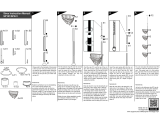
2.0 Installation
Ensure that the mains supply is isolated before proceeding
2.1 Decide on the position the fan is to be
sited; it must be a minimum of 2.3m from
the oor to the lowest point on the fan. (A
shorter 150mm long downrod is supplied
with the fan if required. Refer to the
section on installing the shorter downrod).
2.2 Stick a vibration damper on the
bracket of the J-hook. Fix the ceiling
J-hook (supplied) rmly to a timber joist or
concrete ceiling with the screws supplied
(or similar). Ensure that the xing bracket
in the ceiling is able to support a hanging
weight of 15kg minimum. (Fig A)
2.3 Fit the three blades to the fan body.
(Fig B)
2.4 Hang the fan on the hook with the
safety wire, then hook up the fan on the
black rubber roller making sure that all
wires are clear.
2.5 Connect supply wires to the fan
using the terminal block at the top of the
downrod. (Fig C, next page)
2.6. Secure upper canopy with screws tted to cover the wiring connections.
2.7 Tighten all screws including the earth connections.
2.8 Switch on supply and check fan function.
CEILING JOIST MUST
BE ABLE TO
SUPPORT A
MINIMUM OF 15kg
THE SURFACE MUST
BE HORIZONTAL
RUBBER ROLLER
UPPER CANOPY
SCREWS
DOWN ROD
SAFETY
WIRE
J-HOOK
(SHOWN BROKEN)
Fig. A
FAN BLADE
FAN BLADE
MOUNTING SCREWS
SPRING WASHERS
FAN BLADE
MOUNTING GASKET
FAN MOTOR BODY
Fig. B

4
CEILING FAN
STANDARD ROTATION
RUBBER ROLLER
(DOWNWARD AIRFLOW)
LF LR N
L
N
1 PHASE SUPPLY
(220-240 V 50 Hz)
CEILING FAN
REVERSE ROTATION
RUBBER ROLLER
LF LR N
L
N
1 PHASE SUPPLY
(220-240 V 50 Hz)
CEILING FAN
LF LR N
L
N
1 PHASE SUPPLY
(220-240 V 50 Hz)
LF
L
LR
SPEED
CONTROLLER
Fig. C
(DOWNWARD AIRFLOW)

5
EN
3.0 Instructions for changing to shorter 150mm downrod
Ensure that the mains supply is isolated before proceeding
3.1 Loosen the lower canopy screws and slide the canopy up the downrod.
3.2 Disconnect the Brown (LF), Red (LR) and Blue (N) wires, which run up the downrod
from the lower terminal block located just above fan motor body.
3.3 Disconnect the Earth (Green/
Yellow) wire from the lower
mounting bracket which also runs up
inside the downrod.
3.4 Carefully remove the split pin and
the downrod securing bolt.
3.5 Loosen the upper canopy screws
and slide canopy down the downrod.
3.6 Carefully remove the split pin
and downrod securing bolt and then
disconnect the Earth wire.
3.7 Carefully remove the existing
downrod passing the disconnected
feed wires through the rod along with
the safety wire.
3.8 Replace with the 150mm long
downrod supplied.
3.9 Pass the feed wires through the
new Rod along with the safety wire.
3.10 Replace the upper and lower
downrod securing bolts and split pins.
3.11 The feed wires will need to be
cut and stripped to suit the shorter
rod and then re-connected to the
lower terminal block Brown (LF), Red
(LR) and Blue (N).
3.12 Re-connect all Earth (Green/
Yellow) wires.
3.13 Because the shorter downrod
has been required for our particular
installation, it is recommended that the safety wire is reduced in length to protrude 75mm
above the height of the 150mm downrod. The loop for the safety wire will need re-making by
using a wire rope grip or crimp (Supplied by others). It is essential that the new safety wire
loop will withstand the weight of the fan in the event of it falling.
Important
All xings must be tight before operating the fan. It is advisable to check/inspect all the xings
annually, and re-tighten as nexessary. This fan is guaranteed for one year from the date of
purchase against faulty material or workmanship. In the event that any part is found to be
defective please contact your local supplier stating the nature of the fault and providing
evidence of the date and source of purchase.

14
Waarschuwing!
Een foutief uitgevoerde installatie, afregeling, wijziging, reparatie of onderhoudsbeurt
kan leiden tot materiële schade of verwondingen. Alle werkzaamheden moeten door
erkende, gekwaliceerde vakmensen worden uitgevoerd. Indien het toestel niet volgens
voorschrift wordt geplaatst, vervalt de garantie. Dit apparaat is niet bedoeld voor gebruik
door personen (inclusief kinderen) met verminderde lichamelijke, zintuiglijke of geestelijke
vermogens, of gebrek aan ervaring en kennis, tenzij zij onder toezicht staan of worden
geïnstrueerd over het gebruik van het apparaat door een persoon die verantwoordelijk is
voor hun veiligheid. Kinderen moeten gecontroleerd worden om ervoor te zorgen dat ze
niet met het apparaat spelen.
Wijzigingen voorbehouden
De fabrikant streeft continu naar verbetering van haar producten, en behoudt zich het recht
voor om zonder voorafgaande kennisgeving veranderingen in de specicaties aan te brengen.
De technische details worden als correct verondersteld maar vormen geen basis voor een
contract of garantie. Alle orders worden geaccepteerd onder de standaard condities van onze
algemene verkoop- en leveringsvoorwaarden (op aanvraag leverbaar).
De informatie in dit document kan zonder voorafgaande kennisgeving worden gewijzigd. De
meest recente versie van deze handleiding is altijd beschikbaar op www.mark.nl/downloads.
Algemene waarschuwingen
De installatie moet voldoen aan de geldende plaatselijke en/of landelijke voorschriften. Laat
daarom de Ecofan door een vakbekwaam en gekwaliceerd installateur installeren met
inachtneming van de nationale en internationale regelgeving. Bij een foutieve installatie,
afregeling, wijziging, onderhoudsafhandeling of herstelling vervalt de garantie.
De Ecofan P140 wordt geleverd met 2 stangen met lengtes van:
- 400 mm gemonteerd, met een totale hoogte van 610 mm (van plafond tot basis van het
motorhuis);
- 150 mm stang los geleverd, met een totale hoogte van 360 mm (van plafond tot basis van het
motorhuis).
1.0 Algemeen
1.1 Dit apparaat moet worden geaard.
1.2 Controleer of de spanning en frequentie op zowel de ventilatormotor als de
controlelabels (indien aanwezig) overeenkomen met uw elektrische voeding.
1.3 De installatie moet worden voorzien van een tweepolige werkschakelaar met een
contactscheiding van minimaal 3 mm en beveiligd met een zekering van 5 Amp.
1.4 Zorg ervoor dat de veiligheidsdraad is aangesloten op de beugel van de J-haak voordat u
de ventilator bedient.
Lees dit document door voordat u begint
met de installatie en ingebruikname

15
NL
2.0 Installatie
Zorg ervoor dat de netvoeding is geïsoleerd voordat u verdergaat
2.1 Bepaal de positie waar de ventilator
moet worden geplaatst; deze moet
minimaal 2,3 m van de vloer tot het laagste
punt op de ventilator zijn. (Indien nodig is
er een kortere 150 mm lange stang bij de
ventilator geleverd. Raadpleeg hiervoor
hoofdstuk 3).
2.2 Plak een trillingsdemper op de beugel
van de J-haak. Bevestig de J-haak van het
plafond (meegeleverd) stevig aan een
houten balk of betonnen plafond met de
meegeleverde schroeven (of vergelijkbaar).
Zorg ervoor dat de bevestigingsbeugel
in het plafond een hangend gewicht van
minimaal 15 kg kan dragen. (Fig A)
2.3 Plaats de drie bladen op het
ventilatorhuis. (Fig B)
2.4 Hang de ventilator aan de haak met
het veiligheidsdraad en sluit vervolgens de
ventilator op de zwarte rubberen rol aan
en zorg ervoor dat alle draden vrij zijn.
2.5 Sluit de voedingsdraden aan op de ventilator met behulp van het klemmenblok bovenaan
de stang. (Fig C, volgende pagina)
2.6. Zet de bovenste kap vast met schroeven om de bedradingsverbindingen te bedekken.
2.7 Draai alle schroeven vast, inclusief de aardverbindingen.
2.8 Schakel de voeding in en controleer de ventilatorfunctie.
PLAFOND MOET
MINIMAAL 15kg
KUNNEN DRAGEN
HET OPPERVLAK MOET
HORIZONTAAL ZIJN
RUBBEREN ROLLER
BOVENSTE KAP
SCHROEVEN
STANG
VEILIGHEIDS-
DRAAD
J-HAAK
Fig. A
VENTILATORBLAD
VENTILATORBLAD
MONTAGE SCHROEVEN
TANDVERING
VENTILATORBLAD
MONTAGE PAKKING
VENTILATORHUIS
Fig. B

16
PLAFONDVENT.
STANDAARD ROTATIE
RUBBEREN ROLLER
(NEERWAARTSTE
LUCHTSTROOM)
LF LR N
L
N
1 FASE VOEDING
(220-240 V 50 Hz)
PLAFONDVENT.
OMGEKEERDE ROTATIE
RUBBEREN ROLLER
LF LR N
L
N
1 FASE VOEDING
(220-240 V 50 Hz)
PLAFONDVENT.
LF LR N
L
N
1 FASE VOEDING
(220-240 V 50 Hz)
LF
L
LR
TOEREN-
REGELAAR
Fig. C
(NEERWAARTSTE
LUCHTSTROOM)

17
NL
3.0 Instructies voor het omschakelen naar 150 mm stang
Zorg ervoor dat de netvoeding is geïsoleerd voordat u verdergaat
3.1 Draai de onderste schroeven van de kap los en schuif de kap op de stang.
3.2 Ontkoppel de bruine (OF), rode (LR) en blauwe (N) draden, die langs de stang omhoog
lopen vanaf het onderste aansluitblok dat zich net boven het ventilatormotorlichaam bevindt.
3.3 Koppel de aardedraad (groen / geel)
los van de onderste montagebeugel die ook
omhoog loopt in de stang.
3.4 Verwijder voorzichtig de splitpen en de
borgbout van de stang.
3.5 Draai de bovenste kapschroeven los en
schuif de kap naar beneden over de stang.
3.6 Verwijder voorzichtig de splitpen en
de borgstang van de stang en ontkoppel
vervolgens de aarddraad.
3.7 Verwijder voorzichtig de bestaande
stang die de losgekoppelde invoerdraden
samen met het veiligheidsdraad door de
stang voert.
3.8 Vervang door de meegeleverde 150 mm
lange stang.
3.9 Leid de voedingsdraden samen met de
veiligheidsdraad door de nieuwe stang.
3.10 Vervang de bovenste en onderste
stangbevestigingsbouten en splitpennen.
3.11 De voedingsdraden moeten worden
gesneden en gestript om te passen bij de
kortere stang en vervolgens opnieuw worden
aangesloten op het onderste aansluitblok
Bruin (LF), Rood (LR) en Blauw (N).
3.12 Sluit alle aardedraden (groen / geel)
opnieuw aan.
3.13 Omdat de kortere stang is vereist voor onze specieke installatie, wordt aanbevolen om
het veiligheidsdraad in lengte te verkleinen om 75 mm boven de hoogte van de stang van 150
mm uit te steken. De lus voor de veiligheidsdraad moet opnieuw worden gemaakt met behulp
van een draadgreep of krimp (geleverd door anderen). Het is van essentieel belang dat de
nieuwe veiligheidsdraadlus bestand is tegen het gewicht van de ventilator in het geval dat deze
valt.
Belangrijk
Alle bevestigingen moeten strak zijn voordat de ventilator wordt gebruikt. Het is raadzaam om
alle bevestigingen jaarlijks te controleren / inspecteren en zo nodig opnieuw vast te draaien.
Deze ventilator heeft een garantie van één jaar vanaf de datum van aankoop tegen defect
materiaal of vakmanschap. In het geval dat een onderdeel defect blijkt te zijn, neem dan contact
op met uw lokale leverancier met vermelding van de aard van de fout en bewijs van de datum
en de bron van aankoop.


MARK BV
BENEDEN VERLAAT 87-89
VEENDAM (NEDERLAND)
POSTBUS 13, 9640 AA VEENDAM
TELEFOON +31(0)598 656600
FAX +31 (0)598 624584
www.mark.nl
MARK EIRE BV
COOLEA, MACROOM
CO. CORK
P12 W660 (IRELAND)
PHONE +353 (0)26 45334
FAX +353 (0)26 45383
www.markeire.com
MARK BELGIUM b.v.b.a.
ENERGIELAAN 12
2950 KAPELLEN
(BELGIË/BELGIQUE)
TELEFOON +32 (0)3 6669254
www.markbelgium.be
MARK DEUTSCHLAND GmbH
MAX-PLANCK-STRASSE 16
46446 EMMERICH AM RHEIN
(DEUTSCHLAND)
TELEFON +49 (0)2822 97728-0
TELEFAX +49 (0)2822 97728-10
www.mark.de
MARK POLSKA Sp. z o.o
UL. JASNOGÓRSKA 27
42-202 CZĘSTOCHOWA ( P O L S K A )
PHONE +48 34 3683443
FAX +48 34 3683553
www.markpolska.pl
S.C. MARK ROMANIA S.R.L.
STR. KOS KAROLY NR. 1 A
540297 TARGU MURES
(ROMANIA)
TEL/FAX +40 (0)265-266.332
www.markromania.ro
CERTIFICATION N°: 17.07.011
AIRSTREAM
CERTIFICATION N°: 17.07.011
AIRSTREAM
CERTIFICATION N°: 17.07.011
AIRSTREAM
CERTIFICATION N°: 17.07.011
AIRSTREAM
/