Page is loading ...

Page 1

Page 2
table of CONTENTS
The packaging of your Airtronics SD-10G 2.4GHz FHSS-3 radio control system has been specially designed for the safe
transportation and storage of the radio control system's components.
. Save the packaging materials for future use if you ever need to send your radio control system to us
for service, or to store your radio control system if you don't plan on using it for an extended period of time.
IMPORTANT When you receive your SD-10G 2.4GHz FHSS-3 radio control system, the transmitter battery may be
unplugged. Before attempting to charge the transmitter battery, open the battery cover by rst pushing the two latches inward,
then by pulling up on the bottom of the battery cover. Carefully plug the connector from the battery into the matching slot in the
transmitter case. The battery connector is polarized and can therefore be plugged in only one way.

Page 3
INTRODUCTION
We appreciate your purchase of the new Airtronics SD-10G 2.4GHz FHSS-3 radio control system. This Operating Manual
is intended to acquaint you with the many unique features of your new state of the art SD-10G 2.4GHz FHSS-3 radio control
system. In designing the SD-10G 2.4GHz FHSS-3 radio control system, our engineers listened to input from our test-pilots and
feedback from our users to design a radio control system that will allow you to extract the maximum performance from your
model, while at the same time making the programming process as easy as possible to accomplish.
Because the SD-10G 2.4GHz FHSS-3 radio control system is highly advanced and is packed with many features for different
model types, this Operating Manual is quite long. Don't be intimidated! This Operating Manual is laid out in such a way as to make
it as easy as possible to nd, understand, and learn to use the features you require. Please read this Operating Manual carefully
so that you may obtain maximum success and enjoyment from the operation of your new SD-10G 2.4GHz FHSS-3 radio control
system. The SD-10G 2.4GHz FHSS-3 radio control system has been designed for the utmost in comfort and precise control of
all types of models. We wish you the best of success and fun with your new purchase.
An index is provided in the back of this Operating Manual to make it easy to nd the information that you're looking for.
Keep this Operating Manual in a safe place with your SD-10G transmitter so that you can use it as a reference book
for any questions you might have regarding your SD-10G 2.4GHz FHSS-3 radio control system.
This equipment has been tested and found to comply with the limits for a Class B digital device, pursuant to Part 15 of the FCC
Rules. These limits are designed to provide reasonable protection against harmful interference in a residential installation. This
equipment generates, uses, and can radiate radio frequency energy and, if not installed and used in accordance with the operating
instructions, may cause harmful interference to radio communications, however, there is no guarantee that interference will not
occur in a particular installation.
If this equipment does cause harmful interference to radio or television reception, which can be determined by turning the
equipment off and on, the user is encouraged to try to correct the interference by one or more of the following measures:
l
Reorient or relocate the receiving antenna.
l
Increase the separation between the equipment and the receiver.
l
Connect the equipment into an outlet on a circuit different from that to which the receiver is connected.
l
Consult the dealer or an experienced technician for help.
This device complies with Part 15 of the FCC Rules and with RSS-210 of Industry Canada. Operation is subject to the following
two conditions:
1) This device may not cause harmful interference, and....
2) This device must accept any interference received, including interference that may cause undesired operation.
WARNING: Changes or modications made to this equipment not expressly approved by Airtronics may void the FCC authorization
to operate this equipment.
RF Exposure Statement
The SD-10G transmitter has been tested and meets the FCC RF exposure guidelines when used with the Airtronics accessories
supplied or designated for this product, and provided at least 20 cm separation between the antenna the user's body is
maintained. Use of other accessories may not ensure compliance with FCC RF exposure guidelines.
This is a high-output full-range radio control system that should well exceed the range needed for any model. For safety, the user
should perform a range check at the area of operation to ensure that the radio control system has complete control of the model
a the farthest reaches of the operational area. A range check can be accomplished using Low Power Mode. For more information,
see page 25 or 36.
Additional 2.4GHz receivers can be purchased and paired with the SD-10G transmitter through the Binding operation. Please
note that due to differences in the implementation of 2.4GHz technology among different manufacturers, only Airtronics brand
2.4GHz FHSS-3 and FHSS-1 aircraft receivers are compatible with your radio control system.
Current compatible receivers include the 92104 10-Channel 2.4GHz FHSS-3 receiver and the 92824 8-Channel, 92674
7-Channel, 92224 6-Channel Mini, 92664 6-Channel Park Flyer, and 92124 5-Channel Mini 2.4GHz FHSS-1 aircraft receivers.
GENERAL

Page 4
l
Be certain to read this Operating Manual in its entirety.
l
'Safety First' for yourself, for others, and for your equipment.
l
Observe all the rules of the ying site or anywhere you
operate your radio control equipment.
l
If at any time during the operation of your model should
you feel or observe erratic operation or abnormality, end
your operation as quickly and safely as possible. DO NOT
operate your model again until you are certain the problem
has been corrected. TAKE NO CHANCES.
l
Your model can cause serious damage or injury, so please
use caution and courtesy at all times.
l
Do not expose the radio control system to water or excessive
moisture.
l
Please waterproof the receiver and servos by placing them
in a water-tight radio box when operating model boats.
l
If you have little to no experience operating models, we
strongly recommend you seek the assistance of experienced
modelers or your local hobby shop for guidance.
l
The low voltage alarm will sound when the transmitter
battery voltage drops to 6.7 volts. If this occurs, stop
using the transmitter as soon as possible, then recharge
the transmitter battery. For more information, see page 19.
This radio control system operates on the 2.4GHz frequency band. The 2.4GHz connection is determined by the transmitter
and receiver pair. Unlike ordinary crystal-based systems, your model can be used without frequency control.
In addition to the FCC Compliance section on the previous page, please observe the following safety and usage precautions
when installing and using your new Airtronics SD-10G 2.4GHz FHSS-3 radio control system.
l
The 2.4GHz frequency band may be used by other devices, or other devices in the immediate area may cause interference on
the same frequency band. Always before use, conduct a bench test to ensure that the servos operate properly. Also, conduct a
range check at the area of operation to ensure that the radio control system has complete control of the model at the farthest
reaches of the operational area.
l
The response speed of the receiver can be affected if used where multiple 2.4GHz radio control systems are being used,
therefore, carefully check the area before use. Also, if response seems slow during use, discontinue use as quickly as possible.
l
If the 2.4GHz frequency band is saturated (too many radio controllers on at once), as a safety precaution, the radio control
system may not bind. This ensures that your radio control system does not get hit by interference. Once the frequencies have
been cleared, or the saturation level has dropped, your radio control system should be able to bind without any problems.
l
Observe any applicable laws and regulations in place at your ying site when using the 2.4GHz radio control system.
l
Unlike frequency bands used with earlier radio control systems, reception with this 2.4GHz radio control system can be
adversely affected by large obstructions and concrete or steel structures between your model and the transmitter. Also, wire
mesh and similar barriers can adversely affect operation. Keep this mind to ensure the safety of your model.
safety and usage precautions
l
Turn the transmitter ON rst and then turn the receiver ON. After using your model, turn the receiver
OFF rst, then turn the transmitter OFF. It can be dangerous if you activate the components in reverse
order as the servos may start up inadvertently.
l
Before use, double-check that the transmitter and receiver batteries are sufciently charged.
l
Never touch the transmitter antenna during use. Doing so may cause loss of transmitter output, making
it impossible to control your model.
l
Before use, the transmitter antenna should be rotated and angled so that the
antenna is as close to perpendicular to the ground as possible during use. After
use, to prevent any chance of damaging the antenna, the antenna should be
rotated and moved into the horizontal stowed position.
l
Do not expose the transmitter to water or
excessive moisture.
l
Do not expose the transmitter to excessive heat or direct sunlight.
Leaving the transmitter out in direct sunlight can damage the
LCD Display.
ON
OFF
Keep Antenna
Perpendicular
to Ground
Do Not Expose to Moisture
or Direct Sunlight

Page 5
Academy of Model Aeronautics
5151 East Memorial Drive
Muncie, IN 47302
Phone (800) 435-9262
Fax (765) 741-0057
www.modelaircraft.org
l
The receiver antenna wires consist of two coaxial cables and two reception wires (the thin tip at the end of the coaxial cables).
When you mount the receiver antenna wires, do not bend the reception wires. Reception performance decreases if the reception
wires are bent.
l
The receiver antenna wires are delicate, therefore, handle with care. Do not pull on the receiver
antenna wires with force. Do not cut or extend the receiver antenna wires.
l
The coaxial cables can be bent into gentle curves, however, do not bend the coaxial cables acutely, or
repeatedly bend them, or the antenna cores can be damaged.
l
When installed in an electric-powered model, keep the receiver antenna wires as far away as possible
from the motor, battery, and electronic speed control (ESC).
l
There is a danger of runaway operation if connectors shake loose during use. Make sure that the receiver, servo(s), and switch
harness connectors are securely tted.
l
The receiver is susceptible to vibration and moisture. Take appropriate measures to
protect against vibration and moisture. The receiver should be wrapped in foam and the
foam should be secured around the receiver to hold it in place. The foam should not be
secured too tightly or the vibration dampening quality will be reduced. Failure to take
appropriate measures could result in damage to the receiver.
l
When installing the receiver, the antenna reception wires (the thin tip at the end of the coaxial cables) should not come into
contact with any carbon or metal components (conductive components). Aircraft fuselages and helicopter frames may contain
conductive components. If mounting the receiver surrounded by conductive materials (for example, a carbon ber fuselage),
mount the receiver so that the antenna reception wires can be extended outside of the model. Reception can be blocked if the
antenna reception wires are shielded inside a carbon ber fuselage.
l
The manufacturer disclaims all responsibility for damages resulting from use of components other than genuine Airtronics
components.
safety and usage precautions
The Academy of Model Aeronautics (AMA) is a national organization representing modelers in the United States. We urge you
to examine the benets of membership, including liability protection in the event of certain injuries. The Academy has adopted
simple and sane rules which are especially pertinent for radio controlled ight as the Ofcial AMA National Model Aircraft Safety
Code, which we have partially reprinted below:
l
I will not y my model aircraft in sanctioned events, airshows or model ying demonstrations until it has been proven to be
airworthy by having been previously, successfully ight tested.
l
I will not y my model higher than approximately 400 feet within 3 miles of an airport without notifying the airport operator.
I will give the right-of-way and avoid ying in the proximity of full-scale aircraft. Where necessary, an observer shall be
utilized to supervise ying to avoid having models y in the proximity of full-scale aircraft. Where established, I will abide by
the safety rules for the ying site I use, and I will not willfully and deliberately y my models in a careless, reckless and/or
dangerous manner.
l
I will have completed a successful radio equipment ground range check before the rst ight of a new or repaired model.
l
I will not y my model aircraft in the presence of spectators until I become a qualied yer, unless assisted by an experienced
helper.
l
I will perform my initial turn after takeoff away from the pit or spectator areas, unless beyond my control.
It is extremely important to install the receiver and route the receiver antenna wires correctly in your model. This will ensure
that your model receives control signals no matter what its posture, attitude, or heading. For more information, see page 24.
Wrap Receiver
in Foam to Protect From
Vibration and Damage
GENERAL

Page 6
FEATURES AND SPECIFICATIONS
l
10-Channel Digital Proportional Computer Radio with Advanced Programming for Competition Aircraft, Helicopters, and Sailplanes
l
New 2.4GHz FHSS-3 Technology
l
Full-Range 92104 10-Channel 2.4GHz FHSS-3 Receiver
l
Compatible with Airtronics 2.4GHz FHSS-1 Aircraft Receivers
l
6 Cell 1500mAH Rechargeable Ni-MH Transmitter Battery
l
Direct Model Select
l
Safety Link Model / Receiver Binding (FHSS-3 Receivers Only)
l
Programmable Custom Menu
l
Easy-to-Read LCD Display
l
Simple Wing and Model Templates
l
Servo Reversing, Centering, End Point Adjustments, and Limits
l
Six Digital Trim Switches
l
LCD-Only Display Switch
l
3-Axis Triple Rates and Bi-Directional Exponential
l
3-Position Programmable Switches
l
2 Programmable Side Levers and Programmable Dial Knob
l
Servo Monitor
l
Stick Monitor
l
A/E/R Triple Rates
l
A/E/R Bi-Directional Exponential
l
9-Point Throttle Curve
l
Throttle Hold
l
Throttle Cut
l
Optional 'Stiff' Control Springs to Fine-Tune Gimbals
l
Optional Throttle Stick Stops
l
User Naming, Model Naming and Model Select
l
FHSS-1, FHSS-3, and PPM-8 Modulation Selection
l
Low-Power Range Check Mode
l
10-Channel Programmable Fail Safe
l
Adjustable Receiver Battery Fail Safe Voltage
l
Trainer System
l
User-Selectable Modes
l
Programmable Channel Assignments
l
Stick Switch Functions
l
Stop Watch, Rhythm, System, and Integral Timers
l
Data Copy, Reset, and Transfer
l
20 Model Memory
l
Add-On Memory Expansion Card and PC Connectivity
l
Cross-Trim
l
2 Programmable Snap Rolls
l
10 Programmable Mixes
l
5 C-Mixes with 9-Point Curves
l
Variable Resistance Lever Assign
l
5 Flight Modes
l
Flight Mode Copy, Delay, and Naming
l
Idle Down
l
Aileron Differential
l
A/E/R Offset
l
Channel Delay
l
Trim
l
Trim Step Resolution
l
Trim Authority
l
Trim Authority
l
Cross-Trim
l
11 Programmable Mixes
l
5 C-Mixes with 9-Point Curves
l
Variable Resistance Lever Assign
l
5 Flight Modes
l
Flight Mode Copy, Delay, and Naming
l
Six Servo Wing Capability
l
Landing Override Mode
l
Servo Monitor
l
Stick Monitor
l
A/E/R Triple Rates
l
A/E/R Bi-Directional Exponential
l
Aileron Differential
l
Landing Differential
l
Landing Flap Freeze Point
l
Landing Crow
l
Camber and Camber Point
l
Channel Delay
l
Trim
l
Trim Step Resolution
l
3 Gyro Gains
l
3 Governors
l
3 Programmable Mixes Plus Revo Mixing
l
5 C-Mixes with 9-Point Curves
l
Variable Resistance Lever Assign
l
5 Flight Modes
l
Flight Mode Copy, Delay, and Naming
l
Advanced Swashplate Control
l
Servo Monitor
l
Stick Monitor
l
A/E/R Triple Rates
l
A/E/R Bi-Directional Exponential
l
9-Point Throttle and Pitch Curves
l
Throttle Cut
l
7-Point Hovering Throttle
l
7-Point Hovering Pitch
l
A/E/R Offset
l
Channel Delay
l
Trim
l
Trim Step Resolution
l
Trim Authority

Page 7
Transmitter
Model: SD-10G (90100)
Output Power: 100mW
Operating Voltage: 6.7v~10.2v
Power Supply: 7.2v 1500mAH Ni-MH (NH6N-1500S)
Current Drain: 240mA
Temperature Range: 32ºF~122ºF (0ºC~50ºC)
Pulse Width: 0.9msec~2.1msec
Weight with Battery: 32.8oz (930gr)
Frequency: 2.4GHz FHSS-3/FHSS-1 Selectable
Model Memory: 20
Memory Expansion Card: Proprietary, 20 Models
Receiver
Model: 92104
Frequency: 2.4GHz FHSS-3
Input Voltage: 4.8v~6.0v
Weight: 0.52oz (15gr)
Dimensions: 1.94 x 1.05 x 0.61in (49.5 x 26.8 x 15.5mm)
Battery Fail Safe Limit: 3.8v~4.6v Adjustable
Connector Type: Universal 'Z'
978411 Aluminum Carrying Case
99103 Adjustable Neck Strap
FEATURES AND SPECIFICATIONS
96750 Stick Tip Extensions
97107 Trainer Cable
Due to the extremely high frame rate that the 92104 10-Channel receiver included with your SD-10G 2.4GHz FHSS-3 radio
control system operates at, we strongly recommend the use of digital servos. If you use analog servos and experience
problems, you will need to either upgrade to digital servos or use one of the available Airtronics 2.4GHz FHSS-1 aircraft receivers.
Airtronics FHSS-1 aircraft receivers operate at a lower frame rate, therefore, analog servos can be used with them without issue.
We recommend using Airtronics brand servos with your SD-10G 2.4GHz FHSS-3 radio control system. See your local Airtronics
dealer for more information and availability.
Torque: 361oz/in (26.0kg/cm @ 4.8v)
423oz/in (30.5kg/cm @ 6.0v)
Speed: 0.19 sec/60º @ 4.8v
0.15 sec/60º @ 6.0v
Dimensions: 1.60 x 0.83 x 1.50in
(40.6 x 21.0 x 38.1mm)
Weight: 2.33oz (66gr)
94780M Digital High-Torque Metal Gear Ball Bearing Servo
Torque: 55oz/in (4.0kg/cm @ 4.8v)
66oz/in (4.8kg/cm @ 6.0v)
Speed: 0.15 sec/60º @ 4.8v
0.12 sec/60º @ 6.0v
Dimensions: 1.06 x 0.47 x 1.18in
(26.9 x 11.9 x 29.9mm)
Weight: 0.80oz (23gr)
94761Z Digital Micro High-Torque High-Speed Ball Bearing Servo
Torque: 92oz/in (6.6kg/cm @ 4.8v)
114oz/in (8.2kg/cm @ 6.0v)
Speed: 0.13 sec/60º @ 4.8v
0.10 sec/60º @ 6.0v
Dimensions: 1.54 x 0.79 x 1.47in
(39.1 x 20.1 x 37.3mm)
Weight: 1.98oz (56gr)
94774M Digital High-Speed Metal Gear Ball Bearing Servo
96817 Memory Expansion Card
97025 USB Adapter Cable
Torque: 42oz/in (3.0kg/cm @ 4.8v)
53oz/in (3.8kg/cm @ 6.0v)
Speed: 0.20 sec/60º @ 4.8v
0.16 sec/60º @ 6.0v
Dimensions: 1.54 x 0.79 x 1.42in
(39.1 x 20.1 x 36.0mm)
Weight: 1.59oz (45gr)
94702Z Digital Standard Servo
Torque: 124oz/in (8.9kg/cm @ 4.8v)
151oz/in (10.8kg/cm @ 6.0v)
Speed: 0.17 sec/60º @ 4.8v
0.13 sec/60º @ 6.0v
Dimensions: 1.54 x 0.79 x 1.47in
(39.1 x 20.1 x 37.3mm)
Weight: 1.98oz (56gr)
94775M Digital High-Power Metal Gear Ball Bearing Servo
Torque: 80oz/in (5.1kg/cm @ 4.8v)
89oz/in (6.4kg/cm @ 6.0v)
Speed: 0.10 sec/60º @ 4.8v
0.08 sec/60º @ 6.0v
Dimensions: 1.59 x 0.83 x 1.04in
(40.3 x 21.0 x 26.4mm)
Weight: 1.77oz (50gr)
94746M Digital Low-Prole Metal Gear Ball Bearing Servo
GENERAL
The nominal input voltage of the 92104 receiver is 4.8v
to 6.0v. A 4 cell Ni-MH or Ni-Cd battery pack is 4.8v and
a 5 cell Ni-MH or Ni-Cd battery pack is 6.0v. If you use a 2 cell
Li-Po battery pack, you MUST use a voltage regulator. For more
information, see page 20.

Page 8
basic model setup order
The information on this page describes the Basic Model Setup Order that you can use to setup a new model. Regardless of the
model you are ying, using the basic functions of the SD-10G transmitter for most applications is easy and will get your model
setup quickly. It's a simple 5-step process.
1) Bind the Receiver to the Transmitter and Position the Receiver Antennas:
l
Turn the transmitter ON and navigate to the SYSTEM>MODULATION menu.
l
Hold down the Bind Button on the receiver. While holding down the Bind Button on the receiver, turn the receiver ON.
l
Release the Bind Button on the receiver. The Bind LED will slowly blink.
l
Scroll down to TRANSMIT BIND CODE and press the YES/+ key. The Bind LED will blink rapidly.
l
After the Bind LED stops blinking rapidly, press the END key. The Bind LED will turn solid.
l
Install the receiver in your model, making sure that the two receiver antenna wires are mounted 90º to each other.
l
Rotate the transmitter antenna so that it is positioned at a 45º angle toward you.
2) Choose a Model Type:
l
Navigate to the SYSTEM>TYPE menu. Press the YES/+ or NO/- keys to select the Model Type that matches your
model, either AERO (Powered Aircraft), GLID (Sailplane), or HELI (Helicopter).
3) Make Model Type Selections:
l
Scroll down to choose the various options related to the Model Type you've chosen.
AERO - Select what type of wing (Normal or Delta), the number of aileron servos (1 or 2), the number of ap servos (1 or 2),
the type of tail (Normal, V-Tail, or Dual Elevator Servos), and how many engines (1 or 2) your model features.
GLID - Select what type of wing (Normal or Delta), the number of aileron servos (2 or 4), the number of ap servos (1, 2,
or 4), and the type of tail (Normal or V-Tail) your model features.
HELI - Select the type of swashplate your model features. Each Swashplate Type features a diagram showing where the
servos are positioned on the swashplate. Choose the Swashplate Type that matches your model.
l
After making your selections, press the ENTER key, then the YES/+ key. The pre-programmed model template will be
loaded into the transmitter.
4) Name Your Model:
l
Navigate to the SYSTEM>MODEL NAME menu and input a name for your model. This will allow you to easily choose this
model again for later use. The Model Name will be displayed on the Top menu so that you know which model is currently
in use.
5) Plug In Servos and Setup Control Surfaces:
l
Navigate to the Surface menu (it's directly below SYSTEM on the Top menu). The upper portion of the Surface menu
displays which servos plug into which channel slots in the receiver. Use this information to plug your servos into the
receiver in the correct order.
l
Use the Surface menu to adjust direction of travel (NOR/REV), centering (CENT) and maximum travel (EPA) in both
directions for each of your servos. Adjust the settings for each servo separately to ensure that the movements are correct
and that the swashplate, dual ailerons, dual elevators, etc, are moving the same amount.
MODULATION
6
6
TYPE
MODEL NAME
6
SURFACE
6
TRANSMIT BIND CODE
AERO, GLID, OR HELI
6
6
REV, CENT, EPA, LIMT
6
SYSTEM

Page 9
tips and suggestions
l
To view our expanding library of specic transmitter setup sheets, visit the SD-10G section of our website at http://www.airtronics.net.
Available transmitter setup sheets are saved in PDF format and bundled in a .zip le.
l
When you see in the lower right corner of a page, this indicates that the current section is continued at the top of the
next page.
l
A voltage regulator is required if your receiver battery voltage output is higher than 6.0 volts.
l
An after-market peak-detection charger and/or cycler can be used to charge the Ni-MH transmitter battery, however, the
battery must rst be removed from the transmitter to be charged. The circuitry within the transmitter will interfere with the
peak-detection charger's normal operation, resulting in over-charging and damaging the battery and possibly the transmitter itself.
l
Up to 10 servos can be plugged into the receiver separately. To utilize the Channel 9/BATT or the Channel 10/BATT slots along
with a battery, you must plug a Y-Harness into the channel slot, then plug the servo into one side of the Y-Harness and the
battery switch harness into the other side of the Y-Harness.
l
It is extremely important that the receiver antenna wires be mounted as described. This will ensure that your model receives
control signals no matter what its posture, altitude, or heading.
l
All receiver channel assignments can be programmed to suit the user. For example, in the default conguration, receiver
channel slot 1 controls Elevator, however, this channel slot can be programmed to control Aileron or control Rudder, etc.
This allows the utmost control for nearly any custom conguration you may require.
l
All switches (right- and left-hand switch arrays), auxiliary levers, auxiliary push-buttons, and the Auxiliary Dial Knob can be
programmed to perform different functions depending on the user's preference. Some of these switches and buttons are
pre-programmed with specic functions based on the Model Type. For default function assignments, please see those specic
sections of this Operating Manual.
l
The radio control system is range checked using the Low Power Mode function. Do not attempt to y with the transmitter in
Low Power Mode. You will be unable to control your model once it is a certain distance away from you.
l
The SD-10G transmitter features a Type function which allows you to quickly set up the transmitter's low-level mixing based
on the type of model you're ying. Common templates for AERO, GLIDER, and HELI model types are provided. For example,
if your model features two aileron servos, two ap servos, and dual elevator servos, choosing these options will automatically
change the transmitter's programming to accommodate this setup. This takes the guess-work out of setting up more complex
models.
Model Type selection is used when setting up a new model and should be done prior to making any programming
changes to your model. When the Model Type selection is changed for the currently selected model, all programming
(including custom programming) for that model will be reset.
l
The SD-10G transmitter features several different safety features that will sound an audible alarm when triggered. If you turn
your SD-10G transmitter ON and it beeps, this is more than likely a safety alarm.
l
The Display Key activates the transmitter's LCD Display without actually turning the transmitter ON. This allows you to
check and/or change programming settings without actually turning the transmitter ON. To turn only the LCD Display ON,
press and hold the DISPLAY Key for ~2 seconds. To turn the LCD Display OFF, press the DISPLAY Key once.
l
The SD-10G transmitter is compatible with FHSS-3 and FHSS-1 Airtronics 2.4GHz aircraft receivers. To bind the transmitter to
an FHSS-1 receiver, the transmitter modulation must rst be changed to FH1.
l
Pressing the YES/+ key when a System menu or an F-Mode menu selection is highlighted will add that selection to the Custom
menu. Selections added to the Custom menu are denoted by a .
l
Models stored on the Memory Expansion Card (if installed), are denoted with an 'M' (i.e. M21:SANWA-04).
l
In the default conguration, the Model Select List contains 10 AERO model types and 10 HELI model types. The Model Type for
any of the 20 models in the Model Select List can be changed using the Type menu.
l
The Direct Model Select function allows you to select one of three of your most-used models from memory without going
through the Model Select menu. This makes it much quicker and easier to load the programming for your three favorite models.
Many of the Tips and Suggestions on the following pages can be found throughout this Operating Manual, however, we have
listed the most important ones here for your convenience.
GENERAL

Page 10
tips and suggestions
l
Pressing both the YES/+ and NO/-keys together will Reset the highlighted programming selection to the Factory Default Setting.
l
When the Top menu is displayed, pressing both the YES/+ and NO/- keys together will Reset the Timer display.
l
You can assign multiple functions to one switch by assigning the same Switch Position Number for each function. For example,
you could assign Elevator Dual Rate 2, Aileron Dual Rate 2, and Rudder Dual Rate 2 on one switch so that all three Dual
Rate functions can be changed at once.
l
Like many SD-10G programming features, Switch Assignments are model-specic. If you would like to keep the same Switch
Assignments from model-to-model for continuity, use the Data Copy function to save the time and effort necessary to re-program
the Switch Assignments for each model.
l
When you use the Data Reset function, ALL model-specic Flight Mode data, Surface Menu data, and model-specic
System programming, such as Switch Assignments, Model Name, Fail Safe settings, and Stick Switches will be Reset to the
factory default settings. Model Type and Modulation settings will NOT be Reset.
l
Increasing LCD Display Contrast can drain the battery more quickly than using a decreased (lower) setting.
l
Unless otherwise noted, all programming changes take effect immediately.
l
When the Memory Expansion Card is installed and Initialized, it is treated as an extension of the SD-10G transmitter's internal
model memory, therefore, model-specic programming data can be created, copied, deleted, etc., directly through the various
System menu selections. You do not need to enter the Memory Pack menu to make changes to models stored on the Memory
Expansion Card.
l
An audible tone is heard when the trim switches reach the center position. This allows you to know when the trim switches
reach the center position without the need to look at the Trim Indicators on the Top menu.
l
The SD-10G transmitter features Digital Trim Memory. Any amount of trim that you set during ight, using either the trim
switches or the YES/+ and NO/- keys from within the Trim menu, is automatically stored in memory for that specic channel
and model, and for that specic Flight Mode (if enabled). The Trim percentage values for each model will automatically be
loaded when the transmitter is turned ON and your model is selected.
l
There is always one Flight Mode Active at all times. In the default conguration, F-MODE N (Normal) is Active. When GLID
Model Type is selected, F-MODE 4 (Land) will be Active when the ap control stick is pulled all the way back.
l
The F-MODE key is used to facilitate programming the individual Flight Modes only and does not turn the Flight Modes ON
or OFF.
l
Prior to takeoff, check the position of the Dual Rate switches to ensure that they are in the positions you want. We recommend
programming maximum control throw when the three-position dual rate switches are either all the way forward or all the way
back, whichever you prefer.
l
The channels displayed in the Surface menu will vary based on Model Type and Model Type selection options selected in the
SYSTEM>MODEL TYPE menu. For example, if your model features dual elevator servos, LE (Left Elevator) and RE (Right
Elevator) will be displayed.
l
End Point Adjustment is not the same as Limits and should not be used in the same manner as Limits. Whereas Limits will
Limit the maximum servo travel in either direction, End Point Adjustment does not. End Point Adjustment is designed to balance
the control throw on both sides of servo travel and can be overridden by other settings, such as Dual Rate. For example, if
you have your End Point Adjustment set to 100%, and you set your Dual Rate to 150%, the servo will travel more than 100%
when Dual Rate is ON, however, if you have your Limits set to 100%, the servo will travel only 100%, regardless of the End
Point Adjustment setting or the Dual Rate setting.
l
Many F-Mode menu functions feature Common or Separate choices. When set to COM (Common), the function settings will be
the same regardless of which Flight Mode the transmitter is operating in. When set to SEP (Separate), you can program different
function settings separately for each Flight Mode.
l
The Delay function does not affect when the servo starts to respond to control stick movement. The Delay affects only the
transit time of the servo.

Page 11
features familiarization
Antenna
Use the diagrams below to familiarize yourself with the different control features of your new SD-10G transmitter. Descriptions of
these features can be found on pages 12 through 13.
FRONT
The features referenced below are general in nature. Features specic to the Model Type (aircraft, helicopter, or sailplane)
can be found in those specic sections of this Operating Manual.
BACK
Throttle/Rudder
Control Stick (Mode 2)
Left-Hand
Switch Array
Right-Hand
Switch Array
Power Switch
Display Key
Direct Model Select Keys
LCD Display
Charging Jack
Aileron/Elevator
Control Stick (Mode 2)
Trim Switch (T2)
Trim Switch (T1)
Trim Switch (T5)
Auxiliary Dial Knob (VR7)
RF Output
Indicators
Trim Switch (T4)
Trim Switch (T3)
Trim Switch (T6)
Navigation Pad
Flight Mode Key
Programming Keys
Auxiliary Lever (VR5)
Auxiliary Lever (VR6)
DIN
Connector
Push-Button
Switch
Push-Button Switch
Left-Hand
Switch Array
Charging
Jack
All switches (right- and left-hand switch arrays),
auxiliary levers, auxiliary push-buttons, and
the Auxiliary Dial Knob can be programmed to
perform different functions depending on the user's
preference. Some of these switches and buttons
are pre-programmed with specic functions based
on the Model Type. For default function assignments,
please see those specic sections of this Operating
Manual.
In the default conguration, the control sticks
are set to Mode 2 as shown above. The
transmitter can be set to Mode 1, Mode 3, or Mode 4.
For more information, see page 41.
Battery
Compartment
Memory Expansion Card Slot
(Inside Battery Compartment)
GENERAL

Page 12
Aileron/Elevator Control Stick: Controls the Aileron and Elevator axes in the default Mode 2 conguration. For information on
changing transmitter modes, see page 41.
Antenna: Transmits the signal from the transmitter to the receiver in the model. The Antenna should be pivoted into the vertical
position during use. When not in use, the Antenna should be pushed down and collapsed into the horizontal position to prevent
damage during handling and transport.
Antenna Reception Wires: The portion of each of the receiver antenna wires that actually receives the transmitter signal.
The Antenna Reception Wires should never be bent or they could be damaged and limit the range of the receiver.
Auxiliary Dial Knob: The Auxiliary Dial Knob is programmable and will perform a different function depending on what function
is assigned to it. For example, the Auxiliary Dial Knob can be programmed to remotely adjust your engine's carburetor mixture.
Auxiliary Lever: Two Auxiliary Levers are featured, one on each side of the transmitter. Each Auxiliary Lever is programmable
and will perform a different function depending on what function is assigned to it. For example, an Auxiliary Lever can be
programmed to control the tow hook release on a glider.
Battery Compartment: Houses the 6 cell 1500mAH Ni-MH battery that powers the transmitter. The transmitter uses a 6 cell battery
for lighter weight and better feel, while still providing long usage time.
Bind Button and Bind LED: Used in the process of Binding the transmitter and receiver. For information on Binding the transmitter
and receiver, see page 23 or 35.
Charging Jack: Used for onboard charging of the 6 cell 1500mAH Ni-MH battery. For information on charging the transmitter
battery, see page 19.
features familiarization
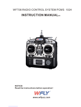
Use the diagram below to familiarize yourself with the 92104 10-Channel receiver included with your new SD-10G 2.4GHz FHSS-3
radio control system. Descriptions of these features can be found below.
All receiver channel assignments can be
programmed to suit the user. For example,
in the default conguration, receiver channel slot
1 controls Elevator, however, this channel slot can
be programmed to control Aileron or control
Rudder, etc. This allows the utmost control for
nearly any custom conguration you may require.
The default receiver channel slot congurations
are shown in the table below:
RECEIVER CHANNEL SLOT AERO GLIDER
HELI
Channel Slot 1
Channel Slot 2
Channel Slot 3
Channel Slot 4
Channel Slot 5
Channel Slot 6
Channel Slot 7
Channel Slot 8
Channel Slot 9/BATT**
Channel Slot 10/BATT**
Elevator
Aileron
Throttle
Rudder
Gear
Flaps
Auxiliary 4
Auxiliary 3
Auxiliary 2 and Battery
Auxiliary 1 and Battery
Elevator
Left Aileron
Motor
Rudder
Gear
Right Aileron
Flaps
Auxiliary 3
Auxiliary 2 and Battery
Auxiliary 1 and Battery
Elevator (Fore/Aft Cyclic)
Aileron (Left/Right Cyclic)
Throttle
Rudder (Tail Rotor)
Gyro
Pitch (Collective)
Governor
Auxiliary 3
Auxiliary 2 and Battery
Auxiliary 1 and Battery
Bind Button
Bind LEDCoaxial Cables
Antenna
Reception
Wires
Data Port*
*Data Port for
Sanwa/Airtronics Software
** To utilize this channel slot along with the battery, you must plug a Y-Harness into the channel slot, then plug the servo into one
side of the Y-Harness and the battery switch harness into the other side of the Y-Harness. For more information, see page 20.

Page 13
The 92104 10-Channel receiver included with your new SD-10G 2.4GHz FHSS-3 radio control system uses universal Airtronics
'Z' connectors which are electronically compatible with the servos of other radio control system manufacturers. The connectors
are rugged, but should be handled with care.
features familiarization
Coaxial Cables: The portion of each antenna wire that extends the Antenna Reception Wires. The Coaxial Cables can be bent
into gentle curves, however, do not bend the Coaxial Cables acutely, or repeatedly bend them, or the antenna wire's cores can
be damaged. For information on mounting the receiver and orientating the receiver antenna wires, see page 24.
DIN Connector: The DIN Connector is where the trainer cable (available separately) is plugged into. It is also used to plug the
Airtronics USB data cable (available separately) between the transmitter and your computer. An adapter to use the transmitter
with a ight simulator can also be plugged into the DIN Connector.
Direct Model Select Keys: The Direct Model Select Keys allow you to select one of three of your most-used models from
memory without going through the Model Select menu. For information on using the Direct Model Select Function, see page 31.
Display Key: Activates the transmitter's LCD Display without actually turning the transmitter ON. This allows you to check
and/or change programming settings without actually turning the transmitter ON. To turn only the LCD Display ON, press and
hold the DISPLAY Key for ~2 seconds. To turn the LCD Display OFF, press the DISPLAY Key once.
Flight Mode Key: Allows you to cycle through the ve different Flight Modes while in the Flight Mode Programming menu.
LCD Display: The heart of the programming and display features of the transmitter. All programming and transmitter display
functions are shown on the LCD Display. The Navigation Pad, the three Programming Keys, and the F-MODE Key to the right of
the LCD Display facilitate transmitter programming. The contrast of the LCD Display can be customized by the user to make it
easily readable in multiple lighting conditions.
Left-Hand Switch Array: The switches grouped on the left side of the transmitter are programmable and each will perform a
different function depending on what function is assigned to it. Each switch has a molded reference number next to it that
corresponds to the programming function in the Switch Assignment menu (the printed label corresponds to the two switches on
the front of the transmitter). Each of the ve switches is a three-position toggle switch except for the switch labeled 19/20/21
which is a spring-loaded switch.
Memory Expansion Card Slot: Holds the Memory Expansion Card (available separately). For information on installing the
Memory Expansion Card, see page 59.
Navigation Pad: The Navigation Pad is used in conjunction with the Programming Keys and the F-MODE Key to facilitate
transmitter programming. The Navigation Pad allows you to quickly and easily move the Programming Cursor up and down, and
right and left. The ENTER Key in the center of the Navigation Pad is used to open the selected menu or programming option.
Power Switch: Turns the transmitter ON and OFF.
Programming Keys: The Programming Keys are used in conjunction with the Navigation Pad and the F-MODE Key to facilitate
transmitter programming. The three Programming Keys consist of the YES/+ (Increase) Key, the NO/- (Decrease) Key, and the
END Key.
Push-Button Switch: Two Push-Button Switches are featured. Each Push-Button Switch is programmable and will perform a
different function depending on what function is assigned to it. For example, a Push-Button Switch can be programmed to control
the Stopwatch function.
RF Output Indicators: Both indicators illuminate when the transmitter is turned ON and transmitting a signal. If one or both of
the RF Output Indicators fails to illuminate, RF output is limited or non-existent. In this case, you should not y.
Right-Hand Switch Array: The switches grouped on the right side of the transmitter are programmable and each will perform
a different function depending on what function is assigned to it. Each switch has a molded reference number next to it that
corresponds to the programming function in the Switch Assignment menu (the printed label corresponds to the two switches on
the front of the transmitter). Each of the four switches is a three-position switch.
Throttle/Rudder Control Stick: Controls the Throttle and Rudder axes in the default Mode 2 conguration. For information on
changing transmitter modes, see page 41.
Trim Switch: Six separate Trim Switches (T 1, T 2, T 3, T 4, T 5, and T 6) are featured. Each Trim Switch will control a different
trim axis depending on which Model Type is selected.
- = Negative (Black)
+ = Positive (Red)
S = Signal (Blue)
When unplugging the servo connectors, it's best not to pull on the servo wire itself. This could result in damage to the servo
wire pins in the plastic plug.
GENERAL

Page 14
Low Voltage Alarm
Throttle High Warning Alarm
Flight Mode Warning Alarm
Trainer Mode Warning Alarm
Power Switch Warning Alarm
transmitter alarms
The SD-10G transmitter is equipped with a Low Voltage Alarm that will sound when the transmitter battery reaches 6.7 volts. If
the Low Voltage Alarm sounds while you are ying, you should land immediately, then recharge the transmitter battery.
If the Low Voltage Alarm sounds even after the transmitter battery has been fully charged it indicates that there is a problem
with either the transmitter or the transmitter battery. If this occurs, please contact Airtronics Customer Service.
The SD-10G transmitter is equipped with a safety feature that will not allow you to use the transmitter if the throttle control stick is not
in the lowest position when you turn the transmitter ON. If the throttle control stick is not in the lowest position when you turn the
transmitter ON, the Throttle High Warning alarm will sound continuously, the red RF Output Indicator will blink, and the LCD Display
will read TH-STICK Hi !! To clear the Throttle High Warning, pull the throttle control stick down to the lowest position. The LCD Display
will read normally, the Throttle High Warning alarm will cease, and both the red and green RF Output Indicators will be illuminated.
The SD-10G transmitter is equipped with a safety feature that will not allow you to use the transmitter if the Flight Mode is not set
to 'N' (Normal) when you turn the transmitter ON. If the Flight Mode is not set to 'N' when you turn the transmitter ON, the Flight
Mode Warning alarm will sound continuously, the red RF Output Indicator will blink, and the LCD Display will read F-MODE
NOT 'N' !! To clear the Flight Mode Warning, set the Flight Mode to 'N' using the Flight Mode Switch (this is different from the
F-MODE Key). The LCD Display will read normally, the Flight Mode Warning alarm will cease, and both the red and green RF
Output Indicators will be illuminated.
The SD-10G transmitter is equipped with a safety feature that will warn you when the transmitter is set to Trainer - Master or
Trainer - Slave when the transmitter is turned ON. If the transmitter is set to Trainer - Master when you turn the transmitter ON,
the Trainer Mode Warning alarm will sound continuously, the red RF Output Indicator will blink, and the LCD Display will read
TRAINER MODE MASTER !! If the transmitter is set to Trainer - Slave when you turn the transmitter ON, the Trainer Mode
Warning alarm will sound continuously, the red RF Output Indicator will blink, and the LCD Display will read TRAINER MODE
SLAVE !! To clear either of the Trainer Mode Warnings, press any of the three Programming Keys, the F-MODE Key, or the
ENTER Key. The LCD Display will read normally, the Trainer Mode Warning alarm will cease, and both the red and green RF
Output Indicators will be illuminated (if set to Slave, only the green RF Output Indicator will blink).
Clearing the Trainer Mode Warning does not change the Trainer setting of the transmitter. When the Trainer Mode Warning
is cleared, the transmitter will still be in Trainer Mode - either set to Master or set to Slave.
The SD-10G transmitter is equipped with a Power Switch Warning alarm that will warn you when the transmitter is turned ON and
there has been no movement of the control sticks or switches for 15 minutes. If the transmitter is left on for 15 minutes or longer
without any input the Power Switch Warning alarm will sound continuously and the LCD Display will read POWER SW ON !! To
clear the Power Switch Warning, either turn the transmitter OFF or press any of the three Programming Keys, the F-MODE Key,
or the ENTER Key.
The SD-10G transmitter features several different safety features that will sound an audible alarm when triggered.
Safety features vary depending on the Model Type selected. Default conguration shown in parenthesis.
ALARM DISPLAY AERO GLIDER
HELI
ALWAYS ACTIVE
ACT/INH (ACTIVE)
ACT/INH (ACTIVE)
ALWAYS ACTIVE
ACT/INH (ACTIVE)
ALWAYS ACTIVE
N/A
ACT/INH (INHIBITED)
ALWAYS ACTIVE
ACT/INH (ACTIVE)
ALWAYS ACTIVE
ACT/INH (ACTIVE)
ACT/INH (ACTIVE)
ALWAYS ACTIVE
ACT/INH (ACTIVE)
In the default AERO conguration, Flight Mode N (Normal) is switch position 10. In the default HELI conguration, Flight
Mode N (Normal) is switch position 22. In the default GLID conguration, the Flight Mode Warning alarm is INHIBITED.

Page 15
custom transmitter ADJUSTMENTS
Every effort has been made to engineer the optimum transmitter weight, balance, and feel in the design of your SD-10G 2.4GHz
FHSS-3 radio control system. For example, the transmitter control sticks are ball bearing-supported for smooth control and use
springs that result in superior feel for most pilots. Some aspects of the transmitter are customizable though, to suit the user's
particular taste.
The length of the control sticks can be adjusted to best suit the way you hold them. In general, pilots who place their thumbs on
top of the control sticks prefer the control sticks to be shorter, and pilots who grasp the control sticks prefer the control sticks to
be longer.
3) Once your are satised with the length of the control stick, thread the bottom half of
the control stick up and tighten it gently against the top half of the control stick.
In the default conguration, the control sticks are adjusted to the shortest length.
1) While holding the base of the control stick, turn the top half of the control stick
counter-clockwise to loosen it.
When lengthening the control sticks, we strongly suggest that you leave at least
four threads inside the top half of each control stick. This will ensure that the
control sticks maintain optimum mechanical security. If you thread the control sticks out
too far, the control sticks might come loose during use.
2) To lengthen the control stick, turn the top half of the control stick counter-clockwise.
The spring tension of the control sticks can be adjusted to suit your preference. Increasing the spring tension makes the control
stick's movement rmer. Decreasing the spring tension makes the control stick's movement softer. The throttle control stick ratchet
can also be adjusted. Loosening the throttle control stick ratchet will make the throttle detents less noticeable. Tightening the
throttle control stick ratchet will make the throttle detents rmer. The throttle detents can even be eliminated for those helicopter
pilots who prefer to have no throttle ratchet.
B
AA
B
B
B
1) Open the battery cover by rst pushing the two latches (A) inward,
then by pulling up on the bottom of the battery cover.
2) Unplug the battery from the transmitter and remove it. Set the battery
aside for now.
3) Remove the four Phillips head screws (B) from the back of the
transmitter, then very carefully pull the back half of the transmitter off.
There are no wires attached between the back half of the transmitter
and the circuit boards inside the transmitter. When the back half of
the transmitter is removed, it can be safely set aside.
Pull the back half of the transmitter straight off to avoid bending or
damaging the battery pins.
GENERAL
Your transmitter includes a set of 'stiff' control stick springs that can be installed in place
of the stock control springs. Install these control stick springs if you prefer an even stiffer
control stick feel than provided after tightening the control stick spring tension as described in
this section. For more information about installing the springs, refer to the spring-specic details
in the Changing Throttle Ratchets and Spring for Mode 1 and Mode 3 on pages 41 and 42.

Page 16
4) To increase the spring tension of the control sticks, tighten
(turn clockwise) the three socket-cap screws (C), using a
1.5mm hex wrench. To decrease the spring tension of the
control sticks, loosen (turn counter-clockwise) the three
socket-cap screws (C), using a 1.5mm hex wrench.
5) To make the throttle control stick detents less noticeable,
loosen the socket-cap screw on the outer ratchet plate (D),
using a 1.5mm hex wrench. To make the throttle control stick
detents rmer, tighten the socket-cap screw on the outer
ratchet plate (D), using a 1.5mm socket-cap wrench.
6) Some helicopter pilots prefer to eliminate the throttle ratchet
completely. To do this, loosen the socket-cap screw on the
outer ratchet plate (D), using a 1.5mm hex wrench until the
throttle detents can't be felt anymore. Next, tighten the socket-cap
screw on the inner throttle plate (E), until you're satised with
the throttle control stick resistance.
custom transmitter ADJUSTMENTS
Any modications made to the transmitter other than adjusting the control stick tension and changing Operating Modes
(see below) will void any and all warranties covered by Airtronics, Inc.
C
C
D
When reinstalling the back half of the transmitter, be very careful that you don't bend or otherwise damage the battery pins (F).
These long battery pins should be carefully slid through the matching holes in the back half of the transmitter before pushing
it down into place.
F
7) When satised with the results carefully reinstall the back half of the transmitter, then reinstall the transmitter battery and plug
it back in. The battery connector is polarized and can therefore be plugged in only one way.
The SD-10G transmitter has the ability to operate in four different Modes as shown in the table below. Changing Operating Modes
can be done by the user and requires changing the Mode Setting in the System menu, then swapping the throttle ratchets and
spring on the control sticks. For information on changing Operating Modes, see page 41.
Left-Side Control Stick
Right-Side Control Stick
CONTROL STICK MODE 1 MODE 2
MODE 3
Rudder/Elevator
Throttle/Aileron
Throttle/Rudder
Elevator/Aileron
Elevator/Aileron
Throttle/Rudder
In the default conguration, the transmitter is set to Mode 2, which is most commonly used in North America.
MODE 4
Throttle/Aileron
Elevator/Rudder
E
The SD-10G transmitter features a Trainer System that allows you to connect two SD-10G transmitters together for the purpose
of training a new pilot or for training a more experienced pilot on a new model. For information on connecting two SD-10G
transmitters together, and programming and using the Trainer System, see page 39.
The Trainer System is compatible ONLY with another SD-10G transmitter. You MUST use the SD-10G Trainer Cable. See
your local Airtronics dealer for more information and availability.
C
Spring
Adjuster
The Memory Expansion Card allows you to store up to 40 models (20 in the SD-10G transmitter and 20 on the Memory Expansion
Card). The Memory Expansion Card can be removed and installed into a different SD-10G transmitter, so that model-specic
programming data can be shared with fellow SD-10G transmitter owners in the eld. When the Memory Expansion Card is installed
and Initialized, it is treated as an extension of the SD-10G transmitter's internal model memory, therefore, model-specic programming
data can be created, copied, deleted, etc., directly through the various System menu selections. There is no need to access the
Memory Expansion Card separately. For more information on installing and initializing the Memory Expansion Card, see page 59.
The Memory Expansion Card is proprietary and can be used only with SD-10G transmitters. See your local Airtronics
dealer for more information and availability.

Page 17
custom transmitter ADJUSTMENTS
The SD-10G 2.4GHz FHSS-3 radio control system includes two throttle stick stops which can be installed to limit the physical
travel of the throttle control stick. In the default conguration, both control sticks move up and down the same amount. Some users,
particularly helictopter pilots, prefer it when the physical travel of the throttle control stick is less than that of the other control stick.
B
AA
B
B
B
1) Open the battery cover by rst pushing the two latches (A) inward,
then by pulling up on the bottom of the battery cover.
2) Unplug the battery from the transmitter and remove it. Set the battery
aside for now.
3) Remove the four Phillips head screws (B) from the back of the
transmitter, then very carefully pull the back half of the transmitter off.
There are no wires attached between the back half of the transmitter
and the circuit boards inside the transmitter. When the back half of
the transmitter is removed, it can be safely set aside.
Pull the back half of the transmitter straight off to avoid bending or
damaging the battery pins.
4) Install the throttle stick stops, using the self-tapping screws provided. You can install both
throttle stick stops to limit both high and low throttle control stick travel, or you can install only
one of the two throttle stick stops to limit either high OR low throttle control stick travel.
5) When satised with the results carefully reinstall the back half of the transmitter, then reinstall
the transmitter battery and plug it back in. The battery connector is polarized and can
therefore be plugged in only one way.
It's important that after you install the throttle stick stops that you recalibrate the control
sticks, following the information in the Control Stick Calibration - User Option section on
page 43. This will ensure that the throttle control stick commands maximum servo travel and
correct End Points even though the physical travel of the throttle control stick is limited.
The amount that transmitter Auxiliary Levers (VR6 and VR7) physically travel can be adjusted to
suit your preference. For example, some users prefer less overall movement and other users
prefer more overall movement. The amount that each Auxiliary Level travels can be adjusted from
15º to 30º in each direction (or 30º and 60º of movement overall).
B
AA
B
B
B
1) Open the battery cover by rst pushing the two latches (A) inward,
then by pulling up on the bottom of the battery cover.
2) Unplug the battery from the transmitter and remove it. Set the battery
aside for now.
3) Remove the four Phillips head screws (B) from the back of the
transmitter, then very carefully pull the back half of the transmitter off.
There are no wires attached between the back half of the transmitter
and the circuit boards inside the transmitter. When the back half of
the transmitter is removed, it can be safely set aside.
Pull the back half of the transmitter straight off to avoid bending or
damaging the battery pins.
When reinstalling the back half of the transmitter, be very careful that you don't bend
or otherwise damage the battery pins. These long battery pins should be carefully slid
through the matching holes in the back half of the transmitter before pushing it down into place.
GENERAL
Changing how much each Auxiliary Lever physically travels does
not change the overall control travel of the servos.

Page 18
custom transmitter ADJUSTMENTS
5) While holding the Auxiliary Lever mounting tabs (C) rmly between your thumb and
index nger, grasp and gently pull the lever off of the mount.
4) Working with one Auxiliary Lever at a time, carefully pull it up
and out of the transmitter case, being careful not to damage
the connected wiring.
6) Reinstall the lever, making sure that the small tab is aligned with the corresponding tick mark that
provides the travel distance and lever position desired.
Notice on the lever a small tab (A) and notice on the mount several molded tick marks
and a hash mark (B).
7) Reinstall the Auxiliary Lever by pushing the mounting tab down into the case, being careful not to damage the connected wiring.
8) Repeat the previous procedures to change the amount of travel and lever position of the second Auxiliary Lever.
9) When satised with the results carefully reinstall the back half of the transmitter, then reinstall the transmitter battery and plug
it back in. The battery connector is polarized and can therefore be plugged in only one way.
A
B
THIS SPACE INTENTIONALLY LEFT BLANK
C
C
When reinstalling the back half of the transmitter, be very careful that you don't bend or otherwise damage the battery pins.
These long battery pins should be carefully slid through the matching holes in the back half of the transmitter before
pushing it down into place.

Page 19
Charging the battery
The SD-10G 2.4GHz FHSS-3 transmitter features a 6 cell 7.2v 1500mAH Ni-MH battery for lighter weight and longer battery life.
The battery is charged directly through the SD-10G transmitter, using the charging jack located in the left side of the SD-10G
transmitter. Please observe the Safety Precautions and Charging Warnings below when charging the transmitter battery.
l
Always follow the charging procedures described below to ensure safe and correct use of your Ni-MH battery.
l
The Ni-MH battery is not fully charged when purchased. It is necessary to charge the Ni-MH battery before operation.
l
Before charging the Ni-MH battery, double-check that the transmitter power switch is in the OFF position.
l
Do not plug the charger into anything other than an AC 110v power outlet. Plugging the charger into anything other than
AC 110v outlet may result in smoking, sparks, or re.
l
Do not throw the Ni-MH battery or abuse it in any manner. Do not dispose of the Ni-MH battery in the re or allow it to overheat.
l
Do not short-circuit the Ni-MH battery terminals with wire or any other object.
An after-market Li-Po battery can be used in place of the stock 6 cell 7.2v 1500mAH Ni-MH transmitter battery. If you decide to
replace the stock battery with a Li-Po battery, please observe the following:
l
Use ONLY a 2 Cell 7.4v Li-Po battery of desired capacity. DO NOT USE A 3 CELL 11.1v LI-PO BATTERY.
l
You MUST remove the battery from the transmitter to charge the battery.
l
When you change the connector on your Li-Po battery, please observe correct polarity. See servo plug diagram above.
WARNING An after-market peak-detection charger and/or cycler can be used to charge the Ni-MH transmitter battery,
however, the battery must rst be removed from the transmitter to be charged. The circuitry within the transmitter will
interfere with the peak-detection charger's normal operation, resulting in over-charging and damaging the battery and possibly
the transmitter itself. Damage caused by charging the battery through the transmitter using anything other than the charger
included with the SD-10G transmitter will not be covered under warranty.
2) Plug the round connector from the charger into the charging jack in the right
side of the transmitter. The charger LED will illuminate red, indicating that the
charger is charging.
3) Transmitter charger output is 150mAH, therefore, it will take approximately 10
hours to recharge a fully-discharged battery. We suggest leaving the charger
on overnight. Once fully-charged, the charger LED will once again illuminate
green. See IMPORTANT note above regarding the rst 5 charges.
110v Wall
Outlet
Charger
To
Charging
Jack
Model: OE-156C
Input Voltage: 110v
Tx Output Voltage: 8.5v@150mA
When you receive your SD-10G 2.4GHz FHSS-3 radio control system, the transmitter battery may be
unplugged. Before attempting to charge the transmitter battery, open the battery cover by rst pushing
the two latches inward, then by pulling up on the bottom of the battery cover. Carefully plug the connector
from the battery into the matching slot in the transmitter case. The battery connector is polarized and
can therefore be plugged in only one way.
- = Negative (Black)
+ = Positive (Red)
- = Negative (Black)
IMPORTANT The battery charger included with your SD-10G transmitter is a capacity-sensing charger. During the
charging process, the charger will sense the battery's maximum capacity, then switch to a 20mAH trickle charge, which
can be left on the transmitter for up to 72 hours after the charging light turns green.
To ensure maximum battery capacity and transmitter usage time, we suggest that the rst 5 charges are 24 hour-total
charges, regardless of when the charging light turns green. For the rst 5 times that you charge the battery, charge for a 24 hour
period, then discharge the battery under normal use until the low voltage alarm sounds. After charging the battery for the rst 5
times using this method, you can subsequently charge the battery for the standard amount of time (until the charging light turns green).
1) Plug the supplied charger into a 110v AC wall socket. The charger LED will illuminate green, indicating that the charger is
plugged in.
GENERAL

Page 20
airborne system connections
Use the diagram below to familiarize yourself with how to connect the switch harness, servos, and receiver battery to your 92104
10-Channel receiver.
An after-market Li-Po battery can be used to power the receiver instead of the standard Ni-Cd or Ni-MH battery. If you decide to
use a Li-Po battery to power the receiver, please observe the following:
l
Use ONLY a 2 Cell 7.4v Li-Po battery of desired capacity with a voltage
regulator. SEE WARNING ABOVE.
l
When you change the connector on your Li-Po battery, please observe correct polarity.
WARNING The receiver can use a battery pack rated from 4.8v to 6.0v. A 2 cell Li-Po battery pack is 7.4v. Because of
the higher voltage, you MUST use a voltage regulator* plugged in between the switch harness and the Li-Po battery to
drop the Li-Po battery voltage to 6.0 volts. If you do not use a voltage regulator, damage to the receiver will result.
- = Negative (Black)
+ = Positive (Red)
S = Signal (Blue)
A receiver battery is not included. The receiver can be powered by a 4.8v (4 cell Ni-MH or Ni-Cd) or a 6.0v (5 cell Ni-MH
or Ni-Cd) battery pack of desired capacity.
Up to 10 servos can be plugged into the receiver separately. To utilize the Channel 9/BATT or the Channel 10/BATT slots
along with a battery, you must plug a Y-Harness into the channel slot, then plug the servo into one side of the Y-Harness
and the battery switch harness into the other side of the Y-Harness.
WARNING Some high-capacity Ni-MH batteries can put out more than 6.0 volts when fully charged. If the battery that you're
using is puts out more than 6.0 volts, a voltage regulator, plugged in between the switch harness and the battery should
be used to drop the battery voltage to 6.0 volts. If you do not use a voltage regulator, damage to the receiver may result.
A vOLTAgE rEguLATOr IS rEquIrEd IF YOur
rECEIvEr BATTErY vOLTAgE OuTPuT IS HIgHEr
THAN 6.0 vOLTS. WE rECOmmENd A SWITCHINg
TYPE rEguLATOr ANd IT muST BE ABLE TO HANdLE
THE AmPErAgE dEmANdS OF THE SErvOS uSEd IN
YOur mOdEL.
The battery can be plugged into any of the channel slots and still power the receiver.
/