Harbor Freight Tools 93359 User manual
- Category
- Power drills
- Type
- User manual

SKU 93359
For technical questions, please call 1-800-444-3353
Page 1
Electric Paint Roller Kit
ASSEMBLY AND OPERATING INSTRUCTIONS
3491 Mission Oaks Blvd., Camarillo, CA 93011
Visit our Web site at http://www.harborfreight.com
Copyright
©
2005 by Harbor Freight Tools
®
. All rights reserved.
No portion of this manual or any artwork contained herein may be reproduced in any shape or form without
the express written consent of Harbor Freight Tools.
For technical questions and replacement parts, please call 1-800-444-3353
93359
Due to continuing improvements, actual product may differ slightly from the product described herein.

SKU 93359
For technical questions, please call 1-800-444-3353
Page 2
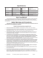
Specifications
Save This Manual
You will need the manual for the safety warnings and precautions, assembly instructions, operating
and maintenance procedures, parts list and diagram. Keep your invoice with this manual. Write the
invoice number on the inside of the front cover. Keep the manual and invoice in a safe and dry place for
future reference.
Safety Warnings and Precautions
WARNING: When using tool, basic safety precautions should always be followed to reduce the
risk of personal injury and damage to equipment.
Read all instructions before using this tool!
1. Keep your work area clean and well lit. Cluttered benches and dark areas invite accidents.
2. Do not operate power tools in explosive atmospheres, such as in the presence of flammable
liquids, gases, or dust. Power tools create sparks which may ignite the dust or fumes.
3. Keep bystanders, children, and visitors away while operating a power tool. Distractions can
cause you to lose control. Protect others in the work area from debris such as chips and sparks.
Provide barriers or shields as needed.
4. Grounded tools must be plugged into an outlet properly installed and grounded in accor-
dance with all codes and ordinances. Never remove the grounding prong or modify the plug
in any way. Do not use any adapter plugs. Check with a qualified electrician if you are in
doubt whether the outlet is properly grounded. If the tool should electrically malfunction or break
down, grounding provides a low resistance path to carry electricity away from the user.
5. Double insulated tools are equipped with a polarized plug (one blade is wider than the other).
This plug will fit in a polarized outlet only one way. If the plug does not fit fully in the outlet,
reverse the plug. If it still does not fit, contact a qualified electrician to install a polarized
outlet. Do not change the plug in any way. Double insulation eliminates the need for the three wire
grounded power cord and grounded power supply system.
6. Avoid body contact with grounded surfaces such as pipes, radiators, ranges, and refrigera-
tors. There is an increased risk of electric shock if your body is grounded.
7. Do not expose power tools to rain or wet conditions. Water entering a power tool will increase
the risk of electric shock.
8. Do not abuse the Power Cord. Never use the Power Cord to carry the tool or pull the Plug
from an outlet. Keep the Power Cord away from heat, oil, sharp edges, or moving parts.
Replace damaged Power Cords immediately. Damaged Power Cords increase the risk of electric shock.
:noitcurtsnoC
gnisuoHenylehteyloP
ebuTnoisnetxEmunimulA
relloRtniaPelbaecalpeR
:ylppuSrewoP
zH06,CAV021
spmA5.0
drocgnorp-3C3XGWA81
:yticapaCtniaPnollaG1:ebuTpUkciPL"91x.D.O"¾x.D.I"½
:eldnaHrelloR
nopanshtiw"9dtS
dle
ihsrettaps
:ebuTtuptuO
kciuqhtiwgnoL.tF01
lortnocdnawdnatcennocsid
:snoisnemiDH"¼7xL"01x.aiD"8:thgieWteNytpm
E.sbL04.5

SKU 93359
For technical questions, please call 1-800-444-3353
Page 3
9. When operating a power tool outside, use an outdoor extension cord marked “W-A” or “W”.
These extension cords are rated for outdoor use, and reduce the risk of electric shock.
Personal Safety
10. Stay alert. Watch what you are doing, and use common sense when operating a power tool.
Do not use a power tool while tired or under the influence of drugs, alcohol, or medication. A
moment of inattention while operating power tools may result in serious personal injury.
11. Dress properly. Do not wear loose clothing or jewelry. Contain long hair. Keep your hair,
clothing, and gloves away from moving parts. Loose clothes, jewelry, or long hair can be caught
in moving parts.
12. Avoid accidental starting. Be sure the Power Switch is off before plugging in. Carrying power
tools with the Power Switch on, or plugging in power tools with the Power Switch on, invites accidents.
13. Remove adjusting keys or wrenches before turning the power tool on. A wrench or a key that is
left attached to a rotating part of the power tool may result in personal injury.
14. Do not overreach. Keep proper footing and balance at all times. Proper footing and balance
enables better control of the power tool in unexpected situations.
15. Use safety equipment. Always wear eye protection. Dust mask, nonskid safety shoes, hard hat,
or hearing protection must be used for appropriate conditions.
Tool Use and Care
16. Use clamps (not included) or other practical ways to secure and support the workpiece to a
stable platform. Holding the work by hand or against your body is unstable and may lead to loss of
control.
17. Do not force the tool. Use the correct tool for your application. The correct tool will do the job
better and safer at the rate for which it is designed.
18. Do not use the power tool if the Power Switch does not turn it on or off. Any tool that cannot be
controlled with the Power Switch is dangerous and must be replaced.
19. Disconnect the Power Cord Plug from the power source before making any adjustments,
changing accessories, or storing the tool. Such preventive safety measures reduce the risk of
starting the tool accidentally.
20. Store idle tools out of reach of children and other untrained persons. Tools are dangerous in
the hands of untrained users.
21. Maintain tools with care. Keep tools maintained and clean. Properly maintained tools are less
likely to bind and are easier to control. Do not use a damaged tool. Tag damaged tools “Do not use”
until repaired.
22. Check for misalignment or binding of moving parts, breakage of parts, and any other condi-
tion that may affect the tool’s operation. If damaged, have the tool serviced before using.
Many accidents are caused by poorly maintained tools.
23. Use only accessories that are recommended by the manufacturer for your model. Accessories
that may be suitable for one tool may become hazardous when used on another tool.

SKU 93359
For technical questions, please call 1-800-444-3353
Page 4
Service
24. Tool service must be performed only by qualified repair personnel. Service or maintenance
performed by unqualified personnel could result in a risk of injury.
25. When servicing a tool, use only identical replacement parts. Use of unauthorized parts or failure
to follow maintenance instructions may create a risk of electric shock or injury.
Specific Safety Rules
1. Maintain labels and nameplates on the tool. These carry important information. If unreadable or
missing, contact Harbor Freight Tools for a replacement.
2. Always wear ANSI approved safety impact eye goggles and heavy work gloves when using the
tool. Using personal safety devices reduce the risk for injury. Safety impact eye goggles and heavy
work gloves are available from Harbor Freight Tools.
3. Maintain a safe working environment. Keep the work area well lit. Make sure there is adequate
surrounding workspace. Always keep the work area free of obstructions, grease, oil, trash, and other
debris. Do not use a power tool in areas near flammable chemicals, dusts, and vapors. Do not use
this product in a damp or wet location.
4. Make sure to read and understand all instructions and safety precautions as outlined in the
manufacturer’s manual.
5. When starting a hand-held power tool, always maintain a firm grip on the tool with both hands
to resist starting torque.
6. Always keep the extension cord away from moving parts on the tool.
7. Avoid unintentional starting. Make sure you are prepared to begin work before turning on the tool.
8. Do not force the tool. This tool will do the work better and safer at the speed and capacity for which
it was designed.
9. Never lay the tool down until the motor has come to a complete stop. The tool may create
unforeseen risk while the motor cycles down.
10. Never leave the tool unattended when it is plugged into an electrical outlet. Turn off the tool,
and unplug it from its electrical outlet before leaving.
11. Always unplug the tool from its electrical outlet before performing and inspection, mainte-
nance, or cleaning procedures.
12. WARNING! Some dust created by power sanding, sawing, grinding, drilling, and other construction
activities, contain chemicals known (to the State of California) to cause cancer, birth defects or other
reproductive harm. Some examples of these chemicals are: lead from lead-based paints, crystalline
silica from bricks and cement or other masonry products, arsenic and chromium from chemically
treated lumber. Your risk from these exposures varies, depending on how often you do this type of
work. To reduce your exposure to these chemicals: work in a well ventilated area, and work with
approved safety equipment, such as those dust masks that are specially designed to filter out micro-
scopic particles.
(California Health & Safety Code 25249.5, et seq.)

SKU 93359
For technical questions, please call 1-800-444-3353
Page 5
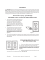
GROUNDING
WARNING! Improperly connecting the grounding wire can result in the risk of electric shock. Check
with a qualified electrician if you are in doubt as to whether the outlet is properly grounded. Do not modify
the power cord plug provided with the tool. Never remove the grounding prong from the plug. Do not use
the tool if the power cord or plug is damaged. If damaged, have it repaired by a service facility before use.
If the plug will not fit the outlet, have a proper outlet installed by a qualified electrician.
This tool has a 3-prong, grounded plug
GROUNDED TOOLS: TOOLS WITH THREE PRONG PLUGS
1. Tools marked with “Grounding Required” have a
three wire cord and three prong grounding plug.
The plug must be connected to a properly
grounded outlet. If the tool should electrically
malfunction or break down, grounding provides a
low resistance path to carry electricity away from
the user, reducing the risk of electric shock. (See
Figure A.)
2. The grounding prong in the plug is connected
through the green wire inside the cord to the
grounding system in the tool. The green wire in
the cord must be the only wire connected to the
tool’s grounding system and must never be
attached to an electrically “live” terminal. (See
Figure A.)
3. Your tool must be plugged into an appropriate outlet, properly installed and grounded in accordance
with all codes and ordinances. The plug and outlet should look like those in the following illustration.
(See Figure A.)
DOUBLE INSULATED TOOLS: TOOLS
WITH TWO PRONG PLUGS
4. Tools marked “Double Insulated” do not require ground-
ing. They have a special double insulation system which
satisfies OSHA requirements and complies with the applicable
standards of Underwriters Laboratories, Inc., the Canadian
Standard Association, and the National Electrical Code. (See
Figure B.)
5. Double insulated tools may be used in either of the 120
volt outlets shown in the following illustration. (See Figure B.)
Figure A
Figure B

SKU 93359
For technical questions, please call 1-800-444-3353
Page 6
detalusnIelbuoD
noitaicossAsdradnatSnaidanaC
.cnI,seirotarobaLsretirwrednU
tnerruCgnitanretlAstloV
serepmA
.nimrepxxxxdaolonetuniMrepsnoituloveRdaoLoN
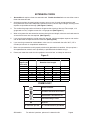
EXTENSION CORDS
1.
Grounded
tools require a three wire extension cord.
Double Insulated
tools can use either a two or
three wire extension cord.
2. As the distance from the supply outlet increases, you must use a heavier gauge extension cord.
Using extension cords with inadequately sized wire causes a serious drop in voltage, resulting in loss
of power and possible tool damage. (See Figure C, below.)
3. The smaller the gauge number of the wire, the greater the capacity of the cord. For example, a 14
gauge cord can carry a higher current than a 16 gauge cord. (See Figure C.)
4. When using more than one extension cord to make up the total length, makesure each cord contains
at least the minimum wire size required. (See Figure C.)
5. If you are using one extension cord for more than one tool, add the nameplate amperes and use the
sum to determine the required minimum cord size. (See Figure C.)
6. If you are using an extension cord outdoors, make sure it is marked with the suffix “W-A” (“W” in
Canada) to indicate it is acceptable for outdoor use.
7. Make sure your extension cord is properly wired and in good electrical condition. Always replace a
damaged extension cord or have it repaired by a qualified electrician before using it.
8. Protect your extension cords from sharp objects, excessive heat, and damp or wet areas.
Figure C.
SYMBOLOGY
V ~
A
Recommended Minimum Wire Gauge for 120 Volt Extension Cords*
Nameplate
Amperes
(
At
Full Load)
Extension Cord Length
25 Feet 50 Feet 75 Feet 100 Feet 150 Feet
0 - 2.0
18 18 18 18 16
2.1 - 3.4
18 18 18 16 14
3.5 - 5.0
18 18 16 14 12
6.1 - 7.0
18 16 14 12 12
7.1 - 12.0
16 14 12 10 X
12.1 - 16.0
14 12 10 X X
16.1 - 20.0
12 10 X X X

SKU 93359
For technical questions, please call 1-800-444-3353
Page 7
Unpacking
When unpacking, check to make sure that all accessories listed below are included, and that the product
is intact and undamaged.
Self Contained Electric Painting Unit with Lid, Paint Can Holder and Paint Feed Hose
Paint Roller Handle with Roller and Snap-on spatter shield
Aluminum Extension Tube with Quick Disconnects
If any parts are missing or broken, please call Harbor Freight Tools at the number on the cover of
this manual.
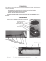
Components
These are the main components of your Electric Paint Roller Kit.
Paint Can Lid (13)
Suction Tube (14)
Pump Assembly (15)
Tension Band (10)
Latch (06)
Handle Assembly (41)
Handle Button (24)
Extension Tube (34)
Roller Arm Coupling (35)
Roller Arm (39)
Paint Roller (43)
Spatter Shield (46)
Locking Tab (38)
Roller Bushing (42)

SKU 93359
For technical questions, please call 1-800-444-3353
Page 8
Cleaning
Purging the Paint Roller
1. When you have completed painting, it is important to clean the Electric Paint Roller Kit. First remove
the Suction Tube (14) from the Paint Can (12) and place it into a can of paint cleaning solution, such
as water. NOTE: The cleaning solution will depend on the type of paint being used. See specific
cleaning instructions on page 9.
2. Remove the Spatter Shield (46) by pulling it off the Paint Roller assembly. Remove the Paint Roller
(43) and Roller Spindle (44) from the Roller Arm (39). To do this, press down the lever on the Locking
Tab (38), then pull the Paint Roller Assembly off the Roller Arm.
3. Further disassemble the Roller Assembly by placing your thumb into the opening in the Roller
Bushing (42), and pry it out of the Paint Roller (43). Place the Paint Roller components into a bucket
or sink prior to being washed.
4. Remove the Paint Can Lid (13) and place it in the bucket for cleaning.
5. Hold the Roller Arm (39) over the open Paint Can (12). With the Selector Switch turned to the “Paint”
setting, press the Handle Button (24) to pump paint remaining in the tool back into the Paint Can.
Stop pumping by releasing the Handle Button (24) when the paint has been pumped through and
cleaning fluid starts to come out of the Roller Arm (39).
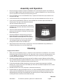
Assembly and Operation
1. Be sure your paint is properly stirred or mixed before use. Unstirred paint pigments at the bottom of
the Paint Can WILL clog this tool. Remove the lid from a 1 gallon standard paint can. Press the Paint
Can Lid (13) from this kit securely on the top of the paint can.
2. Place the lidded paint can on the Motor Base (01). Tighten the Tension Band (10) around the can
using the Latch (06).
3. Insert the Suction Tube (14) through the Paint Can Lid (13) and to the bottom of the Paint Can (12).
4. If you want to use the Extension Tube (34), insert the Roller Arm Connector (40) into the Roller Arm
Coupling (35). Then press the Extension Connector
(33) into the Handle Connector (27).
5. If you do not want to use the Extension, simply press
the Roller Arm Connector (40) directly into the Handle
Connector (27).
6. Attach the Spatter Shield (46) over the Roller (43) by
pressing it in place onto the Locking Tab (38) and the
Roller Bushing (42).
7. Observing workplace safety warnings, plug in the
Power Cord (16) to an appropriate power source.
Move the Selector Switch (02) to the “Paint” position.
8. Press the Handle Button (24), the Pump Assembly
(15) will begin to operate, causing paint to flow
through the handle into the Paint Roller (43).
9. Apply the paint to the work surface, by rolling it on. Press the Handle Button (24) periodically as
needed to reload the paint in the Paint Roller (43).
Selector Switch (02)
REV 02/07

SKU 93359
For technical questions, please call 1-800-444-3353
Page 9
Cleanup for Latex Paint
After purging the Paint Roller, use these steps for latex paints only.
1. Place a large empty bucket on a counter or shelf higher than the container of cleaning solution. Warm
soapy water is recommended for latex paints. Be sure the empty bucket has greater capacity than the
container of water.
2. Hang the Roller Arm (39) onto the empty container so that water pumped through it will flow into the container.
3. Move the Selector Switch to the “Clean” position. This will cause the Pump (15) to operate without
pressing the Handle Button (24).
4. While the unit is self-cleaning, HAND CLEAN the Paint Roller (43), Roller Core (45) and Spatter Shield (46).
5. When all the cleaning solution has been pumped through, elevate the Main Unit above the Handle Assem-
bly and continue to run the Pump Assembly (15) until all the cleaning solution has been purged from the
unit.
6. Move the Selector Switch to “Off” and unplug the unit.
NOTE: Some paint residue will remain in the tubes, but this will not harm the unit or impair future painting
performance.
7. If you are using the Extension, press the tabs on the Roller Arm Coupling (35) of the Extension Tube
(34) and pull out the Roller Arm (39). Press the tab on the Handle Connector (27) and remove the
Extension Tube (34).
8. If you are not using the Extension, press the tab on the Handle Connector (27) and remove the Roller Arm (39).
9. Clean the Handle unit with a damp cloth. CAUTION: DO NOT IMMERSE THE HANDLE UNIT, AS IT WILL
BE DAMAGED.
Cleanup for Oil Based Paint
After purging the Paint Roller, use these steps for oil based paints only.
1. Place the Roller Arm (39) and Suction Tube (14) in a bucket of mineral spirits or other appropriate paint
cleaner.
2. Move the Selector Switch to the “Clean” position. This will cause the Pump (15) to operate without
pressing the Handle Button (24).
3. While the unit is self-cleaning, HAND CLEAN the Paint Roller (43), Roller Core (45) and Spatter Shield (46).
4. After the unit has run for 10 or more minutes, and is clean, follow steps 1-3 for cleaning latex based
paint as listed above.
5. When all the cleaning solution has been pumped through, elevate the Main Unit above the Handle Assem-
bly and continue to run the Pump Assembly (15) until all the cleaning solution has been purged from the
unit.
6. Move the Selector Switch to “Off” and unplug the unit.
NOTE: Some paint residue will remain in the tubes, but this will not harm the unit or impair future painting
performance. CAUTION: When starting on a new paint project, first purge any solvents or paint
pigments in the tubes from the previous clean up.
7. If you are using the Extension, press the tabs on the Quick Release Unit (35) of the Extension Tube
(34) and pull out the Roller Arm (39). Press the tab on the Handle Connector (27) and remove the
Extension Tube (34).
8. If you are not using the Extension, press the tab on the Handle Connector (27) and remove the Roller Arm (39).
9. Clean the Handle unit with a damp cloth. CAUTION: DO NOT IMMERSE THE HANDLE UNIT, AS IT WILL
BE DAMAGED.
REV 02/07

SKU 93359
For technical questions, please call 1-800-444-3353
Page 10
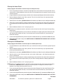
Proper Disposal of Paint and Materials
1. Unused paint and solvents must be disposed of properly. DO NOT simply dump them on the ground or
down a sink. Check with your local authority for appropriate disposal practices and sites in your area.
2. Do not allow children or unauthorized persons to have access to unused paints, solvents and related
materials. These may be harmful or poisonous, potentially causing serious personal injury. Always
keep such materials properly and safely stored.
3. Do not store oily rags in a closed container. WARNING: Oily rags in a closed container or confined
area may spontaneously combust. Such materials may start on fire on their own because of the
chemicals in the rags. Keep oily rags in a well ventilated area in an approved fire safe container, away
from other flammable materials, and dispose of as recommended by your local authority.
Maintenance
1. THOROUGHLY cleaning your Electric Paint Roller after each use is the BEST way to maintain it in
good working condition. It is far EASIER to clean the unit while the paint is still wet than after it has
dried.
2. CAUTION: Be careful not to immerse the Handle Unit and Handle Button. This is an electronic
switch which will be easily damaged by water or solvents. Wipe the Handle Unit clean with a damp
rag.
3. Be sure that your painting tool is empty of all fluids before storage. Drain the hoses and other parts,
and wipe off any excess liquids.
4. Protect your painting tool from rapid temperature changes. Allow it to come to room temperature
before using.
5. When storing the hoses, keep them in large loops, do not allow them to be kinked. Kinks may cause
damage to the hoses.
6. Before storage, carefully clean the connecting areas and quick release tabs of the Handle, Roller Arm
and Extension with a cleaning solution and a brush. Carefully clean and lubricate with petroleum jelly
the O Rings (32) and (65), End Cap Seal (37), and surfaces of the End Cap (36) and Locking Tab (38).
Troubleshooting
Pump won’t operate:
1. Check to be sure that the Power Cord is plugged in to a live outlet.
2. The “Paint” setting on the Selector Switch on the Pump Unit is a “demand” switch. The pump will
operate only if the Handle Button is also pressed. Be sure both switches are in the ON position. The
“Clean” setting on the Selector Switch will cause the Pump to operate continuously. Check for loose
connections or corrosion in both of these switches if the pump won’t operate.
3. Check to be sure the Pump is not clogged with dried paint.
Pump operates but paint won’t flow:
1. Check to be sure the paint is properly stirred and there are no obstructions in the Suction Tube.
2. Check for dried paint or other obstructions clogging the tubes or pump.
REV 02/07

SKU 93359
For technical questions, please call 1-800-444-3353
Page 11
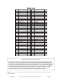
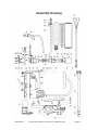
Parts List
NOTE: Some parts are listed and shown for illustration purposes only and are not available individually as
replacement parts.
PLEASE READ THE FOLLOWING CAREFULLY
THE MANUFACTURER AND/OR DISTRIBUTOR HAS PROVIDED THE PARTS DIAGRAM IN THIS MANUAL AS A REFER-
ENCE TOOL ONLY. NEITHER THE MANUFACTURER NOR DISTRIBUTOR MAKES ANY REPRESENTATION OR WAR-
RANTY OF ANY KIND TO THE BUYER THAT HE OR SHE IS QUALIFIED TO MAKE ANY REPAIRS TO THE PRODUCT OR
THAT HE OR SHE IS QUALIFIED TO REPLACE ANY PARTS OF THE PRODUCT. IN FACT, THE MANUFACTURER AND/
OR DISTRIBUTOR EXPRESSLY STATES THAT ALL REPAIRS AND PARTS REPLACEMENTS SHOULD BE UNDERTAKEN
BY CERTIFIED AND LICENSED TECHNICIANS AND NOT BY THE BUYER. THE BUYER ASSUMES ALL RISK AND
LIABILITY ARISING OUT OF HIS OR HER REPAIRS TO THE ORIGINAL PRODUCT OR REPLACEMENT PARTS
THERETO, OR ARISING OUT OF HIS OR HER INSTALLATION OF REPLACEMENT PARTS THERETO.
#traPnoitpircseD.YTQ#traPnoitpircseD.YTQ
10esaBrotoM153gnilpuoCmrArelloR1
20hctiwSrotceleS163paCdnE1
30AeriWgnitcennoC173la
eSpaCdnE1
40gniRgnitcennoC183baTgnikcoL1
50AniPgnitcennoC193mrArelloR1
60hctaL104rotcennoCmrArelloR1
70BniPgnitcennoC114ylbme
ssAeldnaH1
80gnirpSnoisneT124gnihsuBrelloR1
90CniPgnitcennoC134relloRtniaP1
01dnaBnoisneT144eldnipSrelloR1
11AwercSgnippaT
fleS754eroC1
21)dedulcnItoN(naCtniaP064dleihSrettapS1
31diLnaCtniaP174revoCrotoM1
41ebuTnoitcuS184revoCreppUpmuP1
51ylbmessAp
muP194DwercSgnippaTfleS7
61droCrewoP105revoCreppUpmuP1
71tenibaCrotoM115EwercSgnippaTfleS2
81BwercSgnippaTfleS225teksaG1
91pm
alCrotcetorPesoH135raeGtenalP9
02rotcetorPesoH145reirraCraeG2
12pmalCepiP155elxAraeG1
22BeriWgnitcennoC165xoBraeG1
32revoCrep
pUhctiwS175ydoBpmuP1
42nottuBeldnaH185rotoR1
52gnirpS195teksaG1
62hctiwSekatpU106FwercSgnippaTfleS1
72rotcennoCeldnaH116ebuTgnit
cennoC1
82pmalCepiP226pmalCepiP2
92esoHtniaP136gniRO2
03revoCrewoLhctiwS146rotcennoC1
13CwercSgnippaTfleS656gniRO2
23gniRO266leehWp
muP2
33rotcennoCnoisnetxE176elxAleehWpmuP1
43ebuTnoisnetxE186revoCrewoLpmuP1

SKU 93359
For technical questions, please call 1-800-444-3353
Page 12
Assembly Drawing
-
 1
1
-
 2
2
-
 3
3
-
 4
4
-
 5
5
-
 6
6
-
 7
7
-
 8
8
-
 9
9
-
 10
10
-
 11
11
-
 12
12


Harbor Freight Tools 93359 User manual
- Category
- Power drills
- Type
- User manual
Ask a question and I''ll find the answer in the document
Finding information in a document is now easier with AI
Related papers
-
Harbor Freight Tools 69297 User manual
-
-
-
Chicago Electric 55167 User manual
-
Harbor Freight Tools 98871 User manual
-
-
-
-
-
Other documents
-
WAGNER Power Roller Max User manual
-
Pittsburgh Automotive Item 95468 Owner's manual
-
WAGNER SMART Power Roller System User manual
-
Ryobi FPR200 User guide
-
-
-
-
HomeRight C800804 Owner's manual
-
One Stop Gardens 4831 Assembly And Operating Instructions Manual
-