Page is loading ...

Humidication and Evaporative Cooling
INSTALLATION MANUAL
Steam humidifier
Nortec RS
2582419-A EN | 06 AUG 2015

Thank you for choosing Nortec
Installation date (MM/DD/YYYY):
Commissioning date (MM/DD/YYYY):
Site:
Model:
Serial number:
Manufacturer
Nortec Humidity Ltd.
2740 Fenton Road, Ottawa, Ontario K1T3T7
TEL: 1.866.NORTEC1, FAX: 613.822.7964
EMAIL: nortec@humidity.com, WEBSITE: www.humidity.com
Proprietary Notice
This document and the information disclosed herein are proprietary data of Nortec Humidity Ltd. Neither this do-
cument, nor the information contained herein shall be reproduced, used, or disclosed to others without the written
authorization of Nortec Humidity Ltd., except to the extent required for installation or maintenance of recipient's
equipment.
Liability Notice
Nortec Humidity Ltd. does not accept any liability due to incorrect installation or operation of the equipment or due
to the use of parts/components/equipment that are not authorized by Nortec Humidity Ltd.
Copyright Notice
Copyright 2015, Nortec Humidity Ltd. All rights reserved.
Technical modications reserved

3Contents
Contents
1 Introduction 5
1.1 Before You Begin 5
1.2 Notes on the Installation Manual 5
2 For Your Safety 7
3 Product Overview 9
3.1 Models Overview 9
3.1.1 Units Small ("S") and Medium ("M") 9
3.1.2 Units Large ("L") 10
3.2 Identication of the Unit 11
3.3 Product Designation 12
3.4 Options 13
4 Receiving and Storage 15
4.1 Inspection 15
4.2 Storage and Transportation 15
5 Mounting and Installation Work 16
5.1 Safety Notes on Mounting and Installation Work 16
5.2 Installation Overviews 17
5.3 Mounting the Unit 19
5.3.1 Notes on Locating the Unit 19
5.3.2 Mounting the Humidier 21
5.3.2.1 Standard Mounting 21
5.3.2.2 Wall Support Mounting (option) 24
5.3.3 Inspecting the Installed Unit 26
5.4 Steam Line Installation 27
5.4.1 Overview Steam Line Installation for Duct Humidication 27
5.4.2 Installing the Steam Distributors 28
5.4.3 Positioning and Mounting the Blower Packs 29
5.4.4 Installing the Steam and Condensate Lines 30
5.4.5 Common Steam and Condensate Line Errors 35
5.5 Inspecting the Steam Installation 36
5.6 Water Installation 37
5.6.1 Overview Water Installation 37
5.6.2 Notes on Water Installation 38
5.6.3 Inspecting the Water Installation 39
5.7 Notes on Humidity Control Systems/Humidity Control 40
5.7.1 Control Device Locations 40
5.7.2 Admissible Control Signals 40
5.8 Electrical Installation 41
5.8.1 Notes on Electrical Installation 41
5.8.2 Wiring Diagram Nortec RS - Small and Medium Units 42
5.8.3 Wiring Diagram Nortec RS - Large Units 43
5.8.4 Installation Work – External Connections 44
5.8.4.1 Fuses "F3" Voltage Supply 48
5.8.5 Inspecting the Electrical Installation 49
6 Appendix 50
6.1 Unit Dimensions 50

4 Contents

5Introduction
1 Introduction
1.1 Before You Begin
Thank you for purchasing the Nortec RS steam humidier.
The Nortec RS steam humidier incorporates the latest technical ad van ces and meets all recognized
safety standards. Nevertheless, improper use of the Nortec RS steam humidier may result in danger
to the user or third parties and/or damage to property.
To ensure a safe, proper, and economical operation of the Nortec RS steam humidier, please observe
and comply with all information and safety instructions contained in the present documentation as well
as in the separate documentations of the components installed in the humidication system.
If you have questions after reading this documentation, please contact your Nortec representative. They
will be glad to assist you.
1.2 Notes on the Installation Manual
Limitation
The subject of this installation manual is the Nortec RS steam humidier in its different versions.
The various options and accessories are only described insofar as is necessary for proper operation
of the equipment. Further information on options and accessories can be obtained in their respective
instructions.
This installation manual is restricted to the installation of the Nortec RS steam humidier and is meant
for well trained personnel being sufciently qualied for their respective work.
This installation manual is supplemented by various separate items of documentation (operation manual,
spare parts list, etc.), which are included in the delivery as well. Where necessary, appropriate cross-
references are made to these publications in the installation manual.

6 Introduction
Symbols used in this manual
CAUTION!
The catchword "CAUTION" used in conjunction with the caution symbol in the circle designates notes
in this installation manual that, if neglected, may cause damage and/or malfunction of the unit or
damage to property.
WARNING!
The catchword "WARNING" used in conjunction with the general caution symbol designates safety
and danger notes in this installation manual that, if neglected, may cause injury to persons.
DANGER!
The catchword "DANGER" used in conjunction with the general caution symbol designates safety and
danger notes in this installation manual that, if neglected, may lead to severe injury or even death
of persons.
Safekeeping
Please safeguard this installation manual in a safe place, where it can be immediately accessed. If the
equipment changes hands, the documentation must be passed on to the new operator.
If the documentation gets misplaced, please contact your Nortec representative for replacement.

7For Your Safety
2 For Your Safety
General
Every person, who is in charge of the installation work on the Nortec RS must have read and understood
this installation manual and the Nortec RS operation manual before carrying out any work.
Knowing and understanding the contents of the installation manual and the operation manual is a basic
requirement for protecting personnel against any kind of danger, to prevent faulty operation, and to
operate the unit safely and correctly.
All icons, signs and markings applied to the Nortec RS must be observed and kept in readable state.
Qualication of personnel
All installation work described in this installation manual may only be carried out by specialists who
are well trained and adequately qualied and are authorised by the customer.
For safety and warranty reasons any action beyond the scope of this manual must be carried out only
by qualied personnel authorized by the Nortec.
It is assumed that all persons working with the Nortec RS are familiar and comply with the appropriate
regulations on work safety and the prevention of accidents.
Intended use
The Nortec RS steam humidier is intended exclusively for air humidication via a steam distributor or a
blower pack approved by Nortec within specied operating conditions (see Nortec RS operation manual).
Any other type of application, without the written consent of Nortec, is considered as not conforming
with the intended purpose and may lead to hazardous operation of the Nortec RS and will void warranty.
Operation of the equipment in the intended manner requires that all the information contained in this
installation manual are observed.
Danger that may arise from the Nortec RS:
DANGER!
Danger of electric shock!
The Nortec RS is mains powered. Live parts may be exposed when the unit is open. Touching
live parts may cause severe injury or danger to life.
Prevention: The Nortec RS must be connected to the mains only after all mounting and installation
work has been completed, all installations have been checked for correct workmanship and the unit
is closed and properly locked.

8 For Your Safety
Preventing unsafe operation
All persons working with the Nortec RS are obliged to report any alterations to the unit, modications, or
unsafe issues that may affect safety to the owner without delay and to secure the Nortec RS against
accidental power-up.
Prohibited modications to the unit
No modications must be undertaken on the Nortec RS without the express written consent of Nortec.
For the replacement of defective components use exclusively original accessories and spare parts
available from your Nortec representative.

9Product Overview
3 Product Overview
3.1 Models Overview
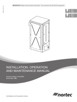
Nortec RS steam humidiers are available in different housing sizes (S, M and L) with different heating
voltages and steam capacities ranging from 10 lbs/hr up to a maximum of 180 lbs/hr (5 ... 80 kg/h).
3.1.1 Units Small ("S") and Medium ("M")
Housing
size
Nortec
RS
208 V/1~ 240 V/1~ 480 V/1~ 600 V/1~ 208 V/3~ 240 V/3~ 480 V/3~ 600 V/3~
lb/hr (kg/hr) lb/hr (kg/hr) lb/hr (kg/hr) lb/hr (kg/hr) lb/hr (kg/hr) lb/hr (kg/hr) lb/hr (kg/hr) lb/hr (kg/hr)
S
10 10.9 (4.9) 10.9 (4.9) 9.7 (4.4) 11.4 (5.2) 10.9 (4.9) 10.9 (4.9) 11.3 (5.1) 11.1 (5.0)
15 15.9 (7.2) 14.5 (6.6) 14.1 (6.4) 14.7 (6.7) 15.9 (7.2) 14.5 (6.6) 14.6 (6.6) 17.6 (8.0)
20 21.2 (9.6) 21.2 (9.6) 18.8 (8.5) 19.6 (8.9) 21.2 (9.6) 21.2 (9.6) 19.4 (8.8) 22.8 (10.3)
M
30 31.8 (14.4) 31.8 (14.4) 31.5 (14.3) 31.4 (14.2) 28.8 (13.1) 31.8 (14.4) 31.5 (14.3) 31.4 (14.2)
45 –– –– –– –– 47.7 (21.6) 47.9 (21.7) 45.2 (20.5) 47.1 (21.4)
65 –– –– –– –– 71.6 (32.5) 71.9 (32.6) 63.0 (28.6) 70.6 (32.0)
90 –– –– –– –– –– –– 94.6 (42.9) 94.3 (42.8)
Fig. 1: Overview units small ("S") and medium ("M")
S
M

10 Product Overview
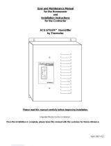
3.1.2 Units Large ("L")
Housing
size
Nortec
RS
208 V/1~ 240 V/1~ 480 V/1~ 600 V/1~ 208 V/3~ 240 V/3~ 480 V/3~ 600 V/3~
lb/hr (kg/hr) lb/hr (kg/hr) lb/hr (kg/hr) lb/hr (kg/hr) lb/hr (kg/hr) lb/hr (kg/hr) lb/hr (kg/hr) lb/hr (kg/hr)
L
90 –– –– –– –– 95.4 (43.3) 94.6 (42.9) –– ––
130 –– –– –– –– 143.2 (65.0) 141.8 (64.3) 126.0 (57.2) 141.2 (64.1)
180 –– –– –– –– –– –– 189.2 (85.8) 188.6 (85.5)
Fig. 2: Overview units large ("L")
L
Module
B
Module
A

11Product Overview
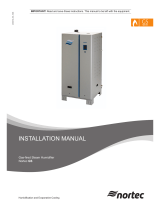
3.2 Identication of the Unit
The identication of the unit is found on the specication label.
Fig. 3: Specication label location and details (right side and underside of unit)
MODEL: SER:RS 010 XXXXXXX
VOLTS: PHASE: HZ:208 1 60
AMPS: 17.8
KW: 3.7
MAX: 25
Circuit Protection 11/14
Type designation
Serial number
Electrical supply requirements
Current draw
Power consumption
Max. external fuse
Month/Year

12 Product Overview
3.3 Product Designation
The product designation and the most important unit data are found on the specication label xed on
the right side of the Nortec RS.
Notes regarding the specication label can be found in the Nortec RS operation manual.
Key model designation
Example:
Nortec RS 65 480V/3~
Product designation
Unit model:
Heating voltage:
208V/1~/50...60Hz: 208V/1~
240V/1~/50...60Hz: 240V/1~
480V/1~/50...60Hz: 480V/1~
600V/1~/50...60Hz: 600V/1~
208V/3~/50...60Hz: 208V/3~
240V/3~/50...60Hz: 240V/3~
480V/3~/50...60Hz: 480V/3~
600V/3~/50...60Hz: 600V/3~

13Product Overview
3.4 Options
Nortec RS
10 15 20 30 45 65 90 130 180
Precision
Provides capability of humidier to achieve
± 1% humidity control*. Solid State Relays
allow for rapid response upon call for humid-
ity, adapting rapidly to humidity demand. This
allows for quick response and tight control of
humidity. Also supplied are two ll valves for
quicker response (turbo mode).
* Humidity control is dependent on a variety
of factors, including design of piping from hu-
midier to distributor, duct characteristics from
distributor to space, control devices and location.
In-eld results may vary. Relative humidity levels
in the supply duct will vary greater than in-space
tolerance levels.
1x P
Scale tank
Provides a separate reservoir underneath the
steam cylinder for scale collection. The addi-
tion of this option reduces maintenance time
signicantly. Minerals removed from the water
during steam production will collect in the scale
reservoir rather than in the tank. For the double
tank humidiers (RS 135 and 180), order two
for each humidier.
1x SC
(2x SC for RS 90 large unit)
2x SC
Built-on Blower Pack
For direct dispersion into a conditioned envi-
ronment.
1x BOBP
(N/A for RS 90 large units)
N/A
Remote operating and fault indication
PCB with relay contacts for the connection of
remote displays for "Operation", "Steam", "Fault"
and "Service".
1xRFI
Accessory Board
PCB with relay contacts for the connection of
remote fan enable (cylinder A/B) as well as
hygiene ush (cylinder A/B).
1x ACC
BACnet MSTP BTL
PCB to provide BTL certied BACnet MSTP.
This option also enables full Master functionality
when using BACnet MSTP.
1x BAC-BTL-MSTP
BACnet IP BTL
PCB to provide BTL certied BACnet IP.
1x BAC-BTL-IP
LonWorks board
Supplementary board to connect the Nortec RS
to a building management system via LonWorks.
1x LON
Mounting bar
Provides two mounting bars which t into each
other for wall mounting. One bar is fastened
to the humidier, the other bar is fastened to
the wall. The unit can then be "hung" onto
the wall by engaging the two mounting bars.
Note: without this option, the unit may still be
wall mounted using the keyhole cutouts on the
back of humidier housing.
1x MP-S
1x MP-M
(1xMP-L for RS 90 large unit)
1x MP-L
Mounting rack basic
Mounting rack for Nortec RS.
1x MR-B-S
1x MR-B-M
(1x MR-B-L for RS 90 large unit)
1x MR-B-L

14 Product Overview
Nortec RS
10 15 20 30 45 65 90 130 180
Height extension proles for
mounting rack basic **
Height extension proles for mounting rack.
1x MR-E
(N/A for RS 90 large unit)
N/A
Adjustable proles for
mounting rack basic **
Proles with screw feet for levelling the
mounting rack.
1x MR-A
(N/A for RS 90 large unit)
N/A
Pressure compensation kit
Provides extension for the ll cup to overcome
back pressure (including duct static pressure)
in excess of 5-1/2" water column. Longer
hoses included. Two required for double tank
humidiers.
1x OPS
(2x OPS for RS 90 large unit)
2x OPS
** Not available for units size "L" (large)

15Receiving and Storage
4 Receiving and Storage
4.1 Inspection
Upon receiving:
– Inspect shipping boxes for damage.
Any damages of the shipping boxes must be reported to the shipping company without delay.
– Check packing slip to ensure all parts have been delivered.
All material shortages are to be reported to your Nortec supplier within 48 hours after receipt of the
goods. Nortec Humidity Ltd. assumes no responsibility for any material shortages beyond this period.
The standard delivery includes the Nortec RS steam humidier with the options ordered (see Sec-
tion 3.4) packed in cardboard boxes along with the installation manual (this document), operation
manual and spare parts list.
– Unpack the parts/components and check for any damage.
If parts/components are damaged, notify the shipping company immediately.
– Check whether the components are suitable for installation on your site according to model key
shown on the specication label.
4.2 Storage and Transportation
Storing
Until installation store the Nortec RS in its original packaging in a protected area meeting the following
requirements:
– Room temperature: 41 ... 104 °F (5 ... 40 °C)
– Room humidity: 10 ... 75 %rh
Transportation
For optimum protection, always transport the unit and components in the original packaging and use
appropriate lifting/transporting devices.
WARNING!
It is the customer's responsibility to ensure that operators are trained in handling heavy goods and that
the operators comply with the appropriate regulations on work safety and the prevention of accidents.
Packaging
Keep the original packaging of the components for later use.
In case you wish to dispose of the packaging, observe the local regulations on waste disposal. Please
recycle packaging where possible.

16 Mounting and Installation Work
5 Mounting and Installation Work
5.1 Safety Notes on Mounting and Installation Work
Qualication of personnel
All mounting and installation work must be carried out only by well qualied personnel authorised by
the owner. It is the owner’s responsibility to verify proper qualication of the personnel.
General notes
Strictly observe and comply with all information given in the present installation manual regarding the
mounting of the unit and the installation of water, steam and electricity.
Observe and comply with all local regulations dealing with water, steam and electrical installations.
Safety
Some installation work requires removal of the unit covers. Please note the following:
DANGER!
Danger of electric shock!
The Nortec RS is mains powered. Live parts may be exposed when the unit is open. Touching
live parts may cause severe injury or danger to life.
Prevention: The Nortec RS must be connected to the mains only after all mounting and installation
work has been completed, all installations have been checked for correct workmanship and the unit
is closed and properly locked.
CAUTION!
The electronic components inside the humidier are very sensitive to electrostatic discharge.
Prevention: To protect these components against damage caused by electrostatic discharge (ESD
protection) appropriate measures must be taken when the unit is open for installation work. A wrist
strap should be worn to connect the maintenance specialist with a common ground point. For more
information, refer to ANSI/ESD-S20.20.

17Mounting and Installation Work
5.2 Installation Overviews
Typical installation for duct humidication
Humidity sensor or
humidity controller
Return duct
Supply duct
Steam line
– As short as possible
– Adequate upslope (min. 10°)/downslope (2.0°)
– No restrictions
– Condensate trap at the lowest point
– Hose or xed pipe
Condensate line
– Min. downslope 1.2°
– No restrictions
– Condensate trap ømin 8" (200 mm)
Water drain connector ø1.18" (ø30 mm)
Water supply connector 1/2" NPT
Water supply pipe
30...80 psi (2...5 bar)
33.8 ... 77.0 °F (1...25 °C)
Air proving switch
(external safety chain)
Electrical disconnect,
high voltage supply
Rmin: 12"
(300 mm)
ømin: 8" (200 mm)
ømin: 1.57" (40 mm)
Drain line:
– internal ø1.18" (ø30 mm)
– constant downslope (min 1.2°) to funnel
– if using DI or RO water, use stainless steel or plastic pipe able to
withstand max. temperature of 140 °F (60 °C)
– must not touch funnel
Open funnel with trap
ideally located 8" (20 cm) lateral off-set to the unit
Calculated absorption distance B
N
to any obstruction
or min. 7.87 ... 9.84 ft (2.4 ... 3 m) if B
N
is unknown
min. 9.84 ft (3 m)
High limit humidistat
(external safety chain)
Pmax 6.03" wc (1500 Pa)
Pmin -4.02" wc (-1000 Pa)
to drain
to cylinder
Filter valve or
Shut-off valve and 5 micron lter
(recommended)
Fig. 4: Typical installation for duct humidication
min. 12" (300 mm)
min. 12" (300 mm)

18 Mounting and Installation Work
Typical installation for room humidication
Fig. 5: Typical installation for room humidication
Steam line
– As short as possible
– Adequate upslope (min. 10°)/downslope (2.0°)
– No restrictions
– Condensate trap at the lowest point
– Hose or xed pipe
Blower Pack
(mounted separated from the steam humidier)
Condensate line
– Min. downslope 1.2°
– No restrictions
– Condensate trap ømin 8" (200 mm)
Filter valve or
Shut-off valve and 5 micron lter
(recommended)
Water drain connector ø1.18" (ø30 mm)
Water supply connector 1/2" NPT
Water supply pipe
30...80 psi (2...5 bar)
33.8 ... 77.0 °F (1...25 °C)
Electrical disconnect,
high voltage supply
ømin: 1.57" (40 mm)
Drain line:
– internal ø1.18" (ø30 mm)
– constant downslope (min 1.2°) to funnel
– if using DI or RO water, use stainless steel or plastic pipe able to
withstand max. temperature of 140 °F (60 °C)
– must not touch funnel
Open funnel with trap
ideally located 8" (20 cm) lateral off-set to the unit
to drain
to cylinder
ømin: 8" (200 mm)

19Mounting and Installation Work
5.3 Mounting the Unit
5.3.1 Notes on Locating the Unit
Fig. 6: Minimal clearances to be observed
Housing Small Medium Large
Housing dimensions
in inch (mm)
X 16.5" (420) 20.9" (530) 29.4" (1000)
Y 14.6" (370) 16" (406) 16" (406)
Z 26.4" (670) 30.7" (780) 30.7" (780)
Net weight in lb (kg) 60 (27.2) 89 (40.3) 179 (81.0)
Operating weight in lb (kg) 89 (40.2) 145 (65.8) 291 (132.0)
Y
X
Z
0"
(0 mm)
min. 36"
(min. 914 mm)
min. 15.75"
(min. 400 mm)
min. 23.62"
(min. 600 mm)
0"
(0 mm)

20 Mounting and Installation Work
The installation site of the Nortec RS depends largely on the location of the steam distributor (see Sec-
tion 5.4.2 and Section 5.4.3). To ensure proper functioning of the steam humidier and to obtain an
optimal efciency, the following points must be considered and observed when choosing the location
for the steam humidier:
– Install the steam humidier so that:
– the length of the steam line is kept as short as possible,
– the minimum bend radius for steam hoses (R= 12" / 300 mm) and of xed pipes (5 x internal
diameter) is maintained,
– the minimum upslope 10° and downslope 2° of the steam hose is maintained.
– For details of mounting the Nortec RS, refer to Section 5.3.2.
CAUTION!
Do not mount the steam humidier directly to the ventilation duct.
– The back panel of the Nortec RS retains heat during operation (max. surface temperature of the
metal housing approx. 140 - 158 °F / 60 - 70 °C). Make sure, therefore, that the construction (wall,
pillar, etc.) to which the unit is to be mounted, does not consist of heat-sensitive material.
– Install the Nortec RS in such a manner that it is freely accessible with sufcient space available
for maintenance purposes. The minimum distances shown in the adjacent illustration must be
maintained.
– The Nortec RS is protected according to IP21. As a safeguard, the humidier should be installed in
a drip-proof location. Admissible ambient conditions must be complied with.
– Do not mount the Nortec RS to hot or very cold walls or near vibrating components.
– The steam humidier Nortec RS must only be installed in rooms with a oor drain.
CAUTION!
If for some reason the Nortec RS must be installed in a location without oor drain, it is mandatory
to provide a leakage monitoring device to safely interrupt the water supply in case of leakage.
– When mounting the Nortec RS use only the mounting materials supplied with the unit. If mount-
ing with the materials supplied is not possible in your particular case, select a method of mounting
that is of similar stability.
– The Nortec RS is designed for installation and operation within buildings (admissible temperature
range 41... 104 °F / 5...40 °C). For outdoor operation the Nortec RS must be placed in a weather
protective housing. If ambient temperatures near or below the freezing point have to be expected,
the protective housing must be equipped with a thermostat controlled heating of sufcient capacity.
The water supply pipe must be equipped with heat-tracing and must be insulated up to the protec-
tive housing. For outdoor operation, the Keep Warm function must be enabled. The installation of
a normally open valve inside the building envelope that will drain water in case of power failure is
highly recommended.
/