Page is loading ...

ABOUT MANUAL
Before installing and using the camera, please read this manual carefully.
Be sure to keep it handy for future reference.
960H SNAP-IT
Outdoor Dome Camera
DWC-V4567WD
DWC-V4567WTIR
12132012

2
PRECAUTIONS
FCC COMPLIANCE
WARNING : Changes or modifications are not expressly approved by the manufacturer.
Do not open or modify.
Do not open the case except during maintenence and installation,
for it may be dangerous and can cause damages.
Do not put objects into the unit.
Keep metal objects and flammable substances from entering the camera.
It can cause fire, short-circuits, or other damages.
Be careful when handling the unit.
To prevent damages, do not drop the camera or subject it to shock or vibration.
Do not install near electric or magnetic fields.
Protect from humidity and dust.
Protect from high temperature.
Be careful when installing near the ceiling of a kitchen or a boiler room,
as the temperature may rise to high levels.
Cleaning :
To remove dirt from the case, moisten a soft cloth with a soft detergent solution and wipe.
Mounting Surface :
The material of the mounting surface must be strong enough to support the camera.
This equipment has been tested and found to comply with the limits for a Class B
digital device, pursuant to part 15 of the FCC rules. These limits are designed to
provide reasonable protection against harmful interference when the equipment is
operated in a residential environment. This equipment generates, uses, and radiates
radio frequency energy; and if it is not installed and used in accordance with the
instruction manual, it may cause harmful interference to radio communications.

3
Table of Contents
Introduction
Installation
Camera OSD Menu and Glossary
Troubleshooting
Warranty Information
Specifications
Features
Parts and Descriptions
Dimensions
Included Accessories
Easy Installation
Mounting Installation
UTP System
4
5
6
7
8
9-13
14
18-34
35
36-37
38-39
Connecting to Monitors
15
Adjusting the Camera
16
Adjusting the 3-Axis Gimbal
17

EATURES*
4
F
DWC-V4567WD/ DWC-V4567WTIR
1/3” 960H High Resolution CCD
700 TV Lines
3.3~12mm Varifocal Auto Iris Lens
70ft Range IR with Intelligent Camera Sync [V4567WTIR Only]
True Day and Night [V4567WTIR Only]
Star-Light (Super Low Light Technology)
EWDR (Electronic Wide Dynamic Range)
3D-DNR (3D Digital Noise Reduction)
HME (Highlight Masking Exposure)
AGC / SMART BLC / AWB
Night-Up
Negative Imaging
Mirror Image Control
UTP / RS485 Built-in
Programmable Privacy Zones (6) & Motion Detection
Easy Icon Driven OSD Menu with Built-In Joystick
Auto Sensing 12VDC or 24VAC with Line Lock
Secondary Video-BNC Output
IP68 Certified (Waterproof)

5
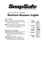
PART & DESCRIPTIONS*
1
3
Lens
2
Power Input Connector
DC 12V /AC 24V Voltage
UTP
4
RS 485
5
Primary Video-BNC Output Connector
6
Camera Control Board
7
Bubble Dome Cover
8
Upper Case
9
Flush Mount Case
10
Surface Mount Case
11
Assembly Screws
#8 - 32 x 0.75
12
Secondary Video-BNC Output Connector
13
Safety Wire
14
Mounting Screws
2
3
4
10
9
6
14
11
7
8
1
13
12
5
NO IR IR

6
DIMENSIONS IN MILLIMETERS (INCHES)*
Flush Mount
Top View
Surface Mount
137(5.39”)
101(3.97”)
17(0.66”)
28(1.10”)
54(2.12”)
98.8(3.88”)
139(5.47”)
139(5.47”)
118.8(4.67”)
36(1.41”)
29(1.14”)
53.8(2.11”)
121(4.76”)
121(4.76”)

7
INSTALLATION*
Included with Outdoor Dome Camera
1. User Manual
2. Mounting Template
3. Second Video Jack
4. Four (4) Screws and Four (4) Dry Wall Anchors
5. L-Wrench
6. TORX-T20 Bolt
7. DC Plug
8. TORX-T20 Wrench
1
2
3
4
5
6
7
8

8
EASY INSTALLATION*

9
9
SURFACE MOUNT INSTALLATION INSTRUCTIONS*
DC 12V
AC 24V
UTP
RS485
1. Use the camera’s mounting
template or your camera to
mark the holes as required.
2. Drill holes into the drywall and
insert the drywall mounts into
the holes.
3. Pull wires through and make
connections.
If you need to keep the wiring within the
within the camera
housing, refer to the diagram below.
4. Mount the surface mount
base (junction box) to the
wall.
5. Snap the camera module onto
the base by aligning the red
and black markings on the
base and the camera module.

10
6. Secure the three (3) assembly
screws.
7. Adjust the camera’s position
by using the 3-Axis Gimbal.
8. Tighten the three locking
screws with the L-Wrench
to secure the cover dome
over the camera.
Flush Mount Installation
For a flush mount housing, remove the surface mount base
(junction box). Cut a large hole on a flat surface for the top part
of the flush mount base. Use the three screws fixed to the base
to secure it to the surface of the wall or ceiling.
Follow steps 6 through 8 of the Surface Mount Installation
Instructions to complete the installation.
3
ST4X35

11
WALL MOUNT INSTALLATION INSTRUCTIONS*
1. Verify all parts are in the box.
2. Insert the wires from the
camera through the wall
mount housing.
3. Use the mounting template to
make pilot holes. Use the dry
wall anchors and woods screws
to attach the assembly.
4. Attach the camera’s surface
mount base (junction box) to
the wall mount.
5. Connect all cables and snap
the camera module onto the
base.
6. Adjust the camera and
secure the dome cover over
the camera module.

12
PENDANT MOUNT INSTALLATION INSTRUCTIONS*
1. Verify all parts are in the box.
2. Attach the top shield to the
pendant mount.
3. Run all necessary cables
from the ceiling to the mount.
4. Use the mounting template
to make pilot holes. Use the
dry wall anchors and wood
screws to attach the assembly
to the wall.
5. Connect all cables and verify
camera is operating properly.
6. Attach the camera to the
ceiling mount and secure the
dome cover properly.

13
CORNER MOUNT INSTALLATION INSTRUCTIONS*
1. Verify all parts are in the box.
2. Attach the two compression fittings to the
corner bracket.
3. Attach the wall mount bracket to the corner
mount using the machine screws.
4. Mount the camera assembly to the corner of
the wall, using wall mount anchors and
machine screws.

14
UTP SYSTEM*
Passive to Passive
Passive to Active
UTP Cable (Max.300ft)
Passive UTP
DVR(Digital Video Recorder)
DVR(Digital Video Recorder)
Monitor
Monitor
Including the passive UTP
UTP Cable (Max.3,000ft)
Including the passive UTP
Active UTP

15
CONNECTING TO MONITORS*
Power Connection - 12V DC / 24V AC Dual Voltage (Auto Polarity Detection and Protection)
All cameras are equipped with a second video output on the camera’s Control Board.
Follow the diagram below to make proper connections to a Monitor or CRT Monitor.
DC 12V / AC 24V
CCTV Monitor
Monitor
300.0
2nd Video Output
Up
Down
Left
Right
NO IRIR

16
ADJUSTING THE CAMERA*
Follow the instructions provided below to make any lens adjustments.
1
Loosen the Zoom & Focus Handles by rotating them counter-clockwise.
Adjust the Field of View by moving the handle to the RIGHT (Tele) to zoom in, or to
the LEFT (Wide) to zoom out.
Adjust the Focus the same way as described able AFTER the desired Zoom position
is established.
Once all desired adjustments have been made, please tighten the handles back by turning
them clockwise.
2
3
4
Zoom:
Focus:
Tele - Wide
Far - Near
Focus
Zoom
NO IRIR

Rotation 360
o
Panning 360
o
NO IR
IR
NO IR
IR
Tilting 90
o
NO IR
Tilting 75
o
IR
17
ADJUSTING 3-AXIS GIMBAL*
The Gimbal mechanism yields maximum rotation and placement as show below.

18
MODULE OSD MENU*
EXPOSURE COLOR DAY NIGHT
FUNCTION MOTION PRIVACY
SYNC SET-UP EXIT
LENS
Manual / DC (0~99)
E. SHUTTER
x256 ~ x2, 1/60, 1/100 FLC,
1/120 ~ 1/100000
BLC (Backlight Compensation)
OFF / ON
MAX-DR (Electronic Wide Dynamic Range)
OFF/ ON (0 ~ 20)
AGC
(Auto Gain Control)
OFF/ LOW / MIDDLE / HIGH
STARLIGHT
OFF, X2 ~ X256
EXIT JUMP
EXIT / SAVE & EXIT / FACTORY SET
WB MODE
AWC / ATW / MANUAL / PUSH
R-Y GAIN
0~255
B-Y GAIN
0~255
EXIT JUMP
EXIT / SAVE & EXIT / FACTORY SET
D&N MODE
AUTO / COLOR / B&W
C-SUP
0~100
A-SUP
0~100
EXIT JUMP
EXIT / SAVE & EXIT / FACTORY SET
MIRROR
OFF/ MIRROR
SHARPNESS
0~25
GAMMA
0.45~1.00 / USER
NEGA
OFF / ON
3D DNR (3D Digital Noise Reduction)
OFF / LOW / MIDDLE/ HIGH
HME
(Highlight Masking Exposure)
OFF / ON
EXIT JUMP
EXIT / SAVE & EXIT / FACTORY SET
MOTION
OFF / ON
SET WINDOW
ALL SET (Set the Entire Screen)
ALL CLEAR (Clear the Entire Screen)
SENSITI. (0~120)
SHOW INDI. (OFF / ICON / TRACE)
DELAY OUT (1~15)
(Motion Alarm Zoom-In Delay)
EXIT JUMP
EXIT / SAVE & EXIT / FACTORY SET
MASK1
OFF / ON
MASK2
OFF / ON
MASK3
OFF / ON
MASK4
OFF / ON
MASK5
OFF / ON
MASK6
OFF / ON
EXIT JUMP
EXIT / SAVE & EXIT / FACTORY SET
CAMERA ID
0~254 (RS485 ID)
TITLE
OFF / ON
DPC (Dead Pixel Cancellation)
OFF / AUTO
MONITOR
CRT / LCD
LANGUAGE
ENGLISH / CHINESE
BAUDRATE.
2400/ 4800/ 9600/ 14400/ 19200/ 38400
(Pelco-D fixed)
OMNI LENS
OFF / 0 (OMNI-Plus Camera only)
EXIT JUMP
EXIT / SAVE & EXIT / FACTORY SET
EXIT
SAVE & EXIT
FACTORY SET
SYNC MODE
INTER. / AUTO
V-PHASE
0~199
EXIT JUMP
EXIT / SAVE & EXIT / FACTORY SET

19
EXPOSURE
LENS
MANUAL
1/60 is the default shutter speed.
Select a shutter speed from X256
to 1/100000.
Select 1/100FLC for flickerless mode.
E. SHUTTER
DC
DC mode supports an
Auto-Iris Varifocal lens.
MANUAL mode supports
a Fixed Board lens
or a Manual Iris lens.
Select DC and control Joystick to
adjust the brightness level from
0~99..

20
Backlight compensation prevents subjects in
defined areas of the scene from appearing
too dark when backlighting is present.
BLC
When BLC is enabled, adjust the BLC Level in five areas in
the screen. Each level can be adjusted from 0 to 255. Move the
joystick controller LEFT and RIGHT to adjust the values in
each area. Move the joystick controller UP and DOWN to
switch between areas. When all adjustments have been
made press the joystick controller to return to the main menu.
Max Dymanic Range provides clear images
even when strong backlighing is present.
Select MAX-DR ON or OFF.
When MAX-DR is ON, BLC will be disabled.
MAX-DR
When ON selected, the Max-DR level
can be adjusted from 0 to 20.
EXPOSURE
1/40