Page is loading ...

M
M
M
7
7
7
V
V
V
I
I
I
P
P
P
i
FCC Statement and Copyright
This equipment has been tested and found to comply with the limits of a
Class B digital device, pursuant to Part 15 of the FCC Rules. These limits
are designed to provide reasonable protection against harmful interference
in a residential installation. This equipment generates, uses and can
radiate radio frequency energy and, if not installed and used in
accordance with the instructions, may cause harmful interference to radio
communications. There is no guarantee that interference will not occur in a
particular installation.
The vendor makes no representations or warranties with respect to the
contents here of and specially disclaims any implied warranties of
merchantability or fitness for any purpose. Further the vendor reserves the
right to revise this publication and to make changes to the contents here of
without obligation to notify any party beforehand.
Duplication of this publication, in part or in whole is not allowed without
first obtaining the vendor’s approval in writing.
The content of this user’s is subject to be changed without notice and we
will not be responsible for any mistakes found in this user’s manual. All the
brand and product names are trademarks of their respective companies.

C
C
C
o
o
o
n
n
n
t
t
t
e
e
e
n
n
n
t
t
t
s
s
s
ii
ENGLISH.............................................................................................1
M7VIP Features................................................................................................................................1
Package contents ...........................................................................................................................3
Layout of M7VIP (For Version 1.0)..............................................................................................4
Layout of M7VIP (For Version 1.1 and above).........................................................................5
CPU Installation...............................................................................................................................6
DDR DIMM Modules: D IMM 1-2-3.................................................................................................7
Jumpers, Headers, Connectors & Slots ...................................................................................9
ESPAÑOL..........................................................................................15
Características del M7VIP...........................................................................................................15
Contenido del Paqu ete................................................................................................................16
Disposición del M7VIP (Para Versión 1.0)..............................................................................17
Disposición del M7VIP (Para Versiones 1.1 en adelante) ..................................................18
Instalación de la CPU...................................................................................................................18
Instalación de la CPU...................................................................................................................19
Módulos DDR DIMM: DIMM1-2-3...............................................................................................20
Puentes, Cabezales, Conectores y Ranuras .........................................................................22
SERIAL ATA CHIP - FASTTRAK 376...................................................28
Step 1: Installing the Hard Drives.............................................................................................28
Step 2: Auto Setup FastBuild™ Configuration Utilit y.........................................................29
Step 3: Installing Software Drivers...........................................................................................35
Step 4: Install PAM Utility ...........................................................................................................42
Using FastBuild™ Configuration Utility.................................................................................48
WARPSPEEDER................................................................................57
Introduction....................................................................................................................................57
System Requirement ...................................................................................................................58
Installation ......................................................................................................................................58
Usage ...............................................................................................................................................59
TROUBLE SHOOTING .......................................................................68
SOLUCIÓN DE PROBLEMAS.............................................................31

M
M
M
o
o
o
t
t
t
h
h
h
e
e
e
r
r
r
b
b
b
o
o
o
a
a
a
r
r
r
d
d
d
D
D
D
e
e
e
s
s
s
c
c
c
r
r
r
i
i
i
p
p
p
t
t
t
i
i
i
o
o
o
n
n
n
1
English
M7VIP Features
Use VIA VT8367 (KT333) / VT8235 Chipset, Winbond W83697HF.
Contains on board I/O facilities, which include two serial ports, a parallel
port, a PS/2 mouse port, a PS/2 keyboard port, audio ports, USB ports and
a game port.
Supports Single Socket-A for an AMD Athlon/ Duron Family processor,
running at 200 or 266 MHz Front Side Bus frequency. (For Version 1.0)
Supports Single Socket-A for an AMD Athlon/ Duron Family processor,
running at 200, 266 or 333 MHz Front Side Bus frequency. (For Version 1.1
and above)
The AMD Athlon system bus supports the 200/266 MHz high-speed,
split-transaction AMD Athlon system bus interface. (For Version 1.0)
The AMD Athlon system bus supports the 200/266/333 MHz high-speed,
split-transaction AMD Athlon system bus interface. (For Version 1.1 and
above)
Supports Ultra DMA 33/66/100/133 Bus Master Modes, PIO Mode 4,
Master Mode, and high performance hard disk drives.
Supports USB2.0 High Speed Device, 2 ports in rear panel and 4 ports in
front panel.
The VT8367 (KT333) system controller is designed to support 200/266/333
MHz DDR SDRAM DIMMs.
Support a maximun memory size up tp 3GB.
Supports one CNR Slot (Type B only), one AGP Slot (AGP 4X), and five
32-bit PCI Bus slots.
Complies with PC ATX form factor specifications.
Supports popular operating systems such as Windows NT, Windows 98SE,
Windows 2000, Windows ME, Windows XP and LINUX.
CPU over temperature protection.

M
M
M
o
o
o
t
t
t
h
h
h
e
e
e
r
r
r
b
b
b
o
o
o
a
a
a
r
r
r
d
d
d
D
D
D
e
e
e
s
s
s
c
c
c
r
r
r
i
i
i
p
p
p
t
t
t
i
i
i
o
o
o
n
n
n
2
Intel® AC’97 2.2 compatible. High S/N ratio meets PC 99 requirements.
Line-in phonejack and Mic-in jack share with rear Audio out for 6 channels
Audio.
Support front audio pin head functions.
Support wake up from USB keyboard/ mouse.
Support 3 ports firewire 1394 function (Optional).
Support 2 serials and 1 parallel Serial ATA and Raid functions (Optional).
Support over speed/ voltage function (Optional).
1394 Features:
OHCI Compliant Programming Interface.
Compliant with 1394 Open HCI Specifications v1.0 and v1.1.
Descriptor based isochronous and asynchronous DMA channels for
receive/ transmit packets.
32-Bit Power-Managed PCI Bus Interface
Compliant with PCI specification v2.2.
Integrated 400 Mbit 3-Port PHY.
Supports provisions of IEEE 1394-1995 Standard.
Fully interoperable with IEEE Std 1394-1995 devices.
PDC20376 Serial ATA-Raid Features:
Single chip, high performance SATA-RAID implementation.
Built in 2 channels SATA PHY, which satisfy SATA 1.0 specification
and can transfer data with 1.5GHz speed.
Additional one parallel ATA interface which satisfy ATA 133
specification.
Bus mastering design takes full advantage of multi-tasking,
multi-threading operating systems and greatly improves
performance.
Provides advance chained packet commands for independent ATA
operations.

M
M
M
o
o
o
t
t
t
h
h
h
e
e
e
r
r
r
b
b
b
o
o
o
a
a
a
r
r
r
d
d
d
D
D
D
e
e
e
s
s
s
c
c
c
r
r
r
i
i
i
p
p
p
t
t
t
i
i
i
o
o
o
n
n
n
3
Compatible with the latest PCI IDE, ATA 7 and enhanced IDE
specifications.
Supports ATA proprosal PIO Mode 0, 1, 2, 3, 4, Ultra DMA Mode 0,
1, 2, 3, 4, 5, 6. The IDE drive transfer rate is capable of up to 150
MB/sec.
Automatically detects whether or not the cable is suitable for mode
3, 4, 5, 6 of Ultra DMA.
Compliance with the PC2000, WHQL hardware requirements.
Package contents
HDD Cable X 1, FDD Cable X 1, Fully Setup Driver CD X 1
Flash Memory Writer for BIOS update X 1
USB Cable X 2 (Optional)
Rear I/O Panel for ATX Case X 1 (Optional)

M
M
M
o
o
o
t
t
t
h
h
h
e
e
e
r
r
r
b
b
b
o
o
o
a
a
a
r
r
r
d
d
d
D
D
D
e
e
e
s
s
s
c
c
c
r
r
r
i
i
i
p
p
p
t
t
t
i
i
i
o
o
o
n
n
n
4
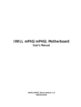
Layout of M7VIP (For Version 1.0)
CPU
BAT1
DIMM1
DIMM2
DIMM3
Socket A
VT8367
(
KT333
)
VT8235
BIOS
CMI9739
Winbo nd
I / O
JATXPWR1
JKBV1
1
JUSBV1
1
1
AGP SLOT
PCI1
PCI2
PCI SLOT
PCI SLOT
PCI3
PCI4
PCI5
PCI SLOT
PCI SLOT
PCI SLOT
CNR1
CNR SLOT
JAUDIO1
1
1
JPANEL1
12
JSFAN1
1
2324
JUSB2
1
2
9
10
JCMOS1
1
JUSBV2
1
JGAME1
GAME Port
SP-OU TM IC -IN LI NE -IN
1
1394
CHIP
J1394C1
RA ID 1
Serials
AT A
Controller
JSATA2JSATA1
JUSB1
1
2
9
10
1
JUSBV3
JDIMMVOLT1
1
2
7
8
IDE1 IDE2 FDD1
J1394B1
1
2
JWOL 1
1
1
2
9
10
J1394A1
9
10
1
2
9
10
1
JCODECSEL1
1

M
M
M
o
o
o
t
t
t
h
h
h
e
e
e
r
r
r
b
b
b
o
o
o
a
a
a
r
r
r
d
d
d
D
D
D
e
e
e
s
s
s
c
c
c
r
r
r
i
i
i
p
p
p
t
t
t
i
i
i
o
o
o
n
n
n
5
Layout of M7VIP (For Version 1.1 and
above)
CPU
BA T1
DIMM1
DIMM2
DIMM3
Socket A
VT8367
(
KT333
)
VT8235
BIOS
CMI9739
Winb ond
I/O
JATXPWR1
JKBV1
1
JUSBV1
1
1
AGP SLOT
PCI1
PCI2
PC I SLOT
PC I SLOT
PCI3
PCI4
PCI5
PC I SLOT
PC I SLOT
PC I SLOT
CNR1
CNR SLO T
JAUDIO1
1
1
JPANEL1
12
JSFAN1
1
2324
JUSB3
1
2
9
10
JCMOS1
1
JUSBV2
1
JGAME1
GA ME Po rt
SP- OUTMI C-I N LIN E-IN
1
1394
CHIP
J1394C1
RA ID 1
Se r i a l s
ATA
Co nt ro lle r
JSATA2J S AT A1
JUSB2
1
2
9
10
1
JUSBV3
JDIMMVOLT1
1
2
7
8
IDE1 IDE2 FDD1
J1394B1
1
2
JWOL1
1
1
2
9
10
J1394A1
9
10
1
2
9
10
JCODECSEL1
1
1 23
654

M
M
M
o
o
o
t
t
t
h
h
h
e
e
e
r
r
r
b
b
b
o
o
o
a
a
a
r
r
r
d
d
d
D
D
D
e
e
e
s
s
s
c
c
c
r
r
r
i
i
i
p
p
p
t
t
t
i
i
i
o
o
o
n
n
n
6
CPU Installation
1. Pull the lever sideways away from the socket then raise the lever up
to 90-degree angle.
2. Locate Pin A in the socket and lock for the white dot or cut edge in
the CPU. Match Pin A with the white dot/cut edge then insert the
CPU.
3. Press the lever down. Then Put the fan on the CPU and buckle it
and put the fan’s power port into the JCFAN1, then to complete the
installation.
CPU/ System Fan Headers: JCFAN1/ JSFAN1/ JNFAN1
C
P
U

M
M
M
o
o
o
t
t
t
h
h
h
e
e
e
r
r
r
b
b
b
o
o
o
a
a
a
r
r
r
d
d
d
D
D
D
e
e
e
s
s
s
c
c
c
r
r
r
i
i
i
p
p
p
t
t
t
i
i
i
o
o
o
n
n
n
7
Note: CPU Over Temperature Protection
When the CPU temperature is over 110°C (for .13µ CPU) or 120°C
(for .18µ CPU), the system will automatically shut-down. If this
situation occurs, please check if your CPU fan is working properly. If
not, change the CPU fan, and then restart the system.
DDR DIMM Modules: DIMM1-2-3
DRAM Access Time: 2.5V Unbuffered/ Registered DDR 1600/ 2100/
2700 Type required.
DRAM Type: 64MB/ 128MB/ 256MB/ 512MB/ 1GB DIMM Module (184
pin)
DIMM Socket
Location
DDR Module Total Memor
y
Size (MB)
DIMM 1 64MB/128MB/256MB/512MB/1GB
*1
DIMM 2 64MB/128MB/256MB/512MB/1GB
*1
DIMM3 64MB/128MB/256MB/512MB/1GB
*1
Max is
3GB
z The list shown above for DRAM configuration is only for reference.
*
If use FSB 333MHz CPU, the Memory run only at DDR333
(PC2700). (For Version 1.1 and above)

M
M
M
o
o
o
t
t
t
h
h
h
e
e
e
r
r
r
b
b
b
o
o
o
a
a
a
r
r
r
d
d
d
D
D
D
e
e
e
s
s
s
c
c
c
r
r
r
i
i
i
p
p
p
t
t
t
i
i
i
o
o
o
n
n
n
8
How to install a DIMM Module
1. The DIMM socket has a
“ Plastic Safety Tab”, and the
DIMM memory module has an
“Asymmetrical notch”, so the
DIMM memory module can only
fit into the slot in one direction.
2. Push the tabs out. Insert the
DIMM memory modules into the
socket at a 90-degree angle, then
push down vertically so that it will
fit into the place.
3. The Mounting Holes and plastic
tabs should fit over the edge and
hold the DIMM memory modules
in place.

M
M
M
o
o
o
t
t
t
h
h
h
e
e
e
r
r
r
b
b
b
o
o
o
a
a
a
r
r
r
d
d
d
D
D
D
e
e
e
s
s
s
c
c
c
r
r
r
i
i
i
p
p
p
t
t
t
i
i
i
o
o
o
n
n
n
9
Jumpers, Headers, Connectors & Slots
Hard Disk Connectors: IDE1/ IDE2
The motherboard has a 32-bit Enhanced PCI IDE Controller that
provides PIO Mode 0~4, Bus Master, and Ultra DMA 33/ 66/ 100/ 133
functionality. It has two HDD connectors IDE1 (primary) and IDE2
(secondary).
The IDE connectors can connect a master and a slave drive, so you can
connect up to four hard disk drives. The first hard drive should always be
connected to IDE1.
Floppy Disk Connector: FDD1
The motherboard provides a standard floppy disk connector that
supports 360K, 720K, 1.2M, 1.44M and 2.88M floppy disk types. This
connector supports the provided floppy drive ribbon cables.
Communication Network Riser S lot: CNR1
The CNR specification is an open Industry Standard Architecture, and it
defines a hardware scalable riser card interface, which supports audio,
and modem only.
Peripheral Component Interconnect Slots: PCI1-5
This motherboard is equipped with 5 standard PCI slots. PCI stands for
Peripheral Component Interconnect, and it is a bus standard for
expansion cards, which has, supplanted the older ISA bus standard in
most ports. This PCI slot is designated as 32 bits.
Accelerated Graphics Port Slot: AGP1
Your monitor will attach directly to that video card. This motherboard
supports video cards for PCI slots, but it is also equipped with an
Accelerated Graphics Port. An AGP card will take advantage of AGP
technology for improved video efficiency and performance, especially
with 3D graphics.
Serial ATA Connector: (JSATA1/ JSATA2) (Optional)
The motherboard has a PCI to SATA Controller with 2 channels SATA
interface, it satisfies the SATA 1.0 spec and can transfer data with
1.5GHz speed. For more details, please refer to page 21(FastTrak
376).

M
M
M
o
o
o
t
t
t
h
h
h
e
e
e
r
r
r
b
b
b
o
o
o
a
a
a
r
r
r
d
d
d
D
D
D
e
e
e
s
s
s
c
c
c
r
r
r
i
i
i
p
p
p
t
t
t
i
i
i
o
o
o
n
n
n
10
Raid Connector: RAID1 (Optional)
This connector supports RAID0 or RAID1 configuration through the
onboard Serial ATA (FastTrak 376) controller chip. Y ou can use the
IDE feature to set up a disk array configuration and to support additional
IDE devices. However, it can only support master mode IDE HDD.
Power Connectors: JATXPWR1
Wake On LAN Header: JWO L1
Front USB Header: JUSB1/ JUSB2/ JUSB3
WOL1
1
5V_SB Wake up
Ground
JATXPWR1
(ATX Main Power Conn.)
JATXPWR1
(
ATX Power Conn.
)
JUSB1/2
(For Version 1.0)
2
1
Pin1,2 ==> +5V
Pin3,4 ==> Data
(
-
)
Pin5,6 ==> Data
(
+
)
Pin7,8 ==> Ground
Pin9 ==> KEY
Pin10 ==> NA
JUSB2/3
(For Version 1.1
and above)
2
1
Pin1,2 ==> +5V
Pin3,4 ==> Data
(
-
)
Pin5,6 ==> Data
(
+
)
Pin7,8 ==> Ground
Pin9 ==> KEY
Pin10 ==> NA

M
M
M
o
o
o
t
t
t
h
h
h
e
e
e
r
r
r
b
b
b
o
o
o
a
a
a
r
r
r
d
d
d
D
D
D
e
e
e
s
s
s
c
c
c
r
r
r
i
i
i
p
p
p
t
t
t
i
i
i
o
o
o
n
n
n
11
5V/ 5VSB Selection for USB: JUSBV1/2/3
5V/ 5VSB Selection for KB: JKBV1
Front 1394 Header: J1394A1/ J1394B1/ J1394C1
(Optional)
Pin 1-2 on ==> 5V
Pin 2-3 on ==> 5V_SB
1
JUSBV1/2/3
1
JKBV1
Pin 1-2 on ==> 5V
Pin 2-3 on ==> 5V
_
SB
JUSB3/4
2
1
Pin1,2 ==> +5V
Pin3,4 ==> Dato(-)
Pin5,6 ==> Dato(+)
Pin7,8 ==> Tierra
Pin9 ==> KEY
Pin10 ==> NA
J1394A1/B1/C1
2
1
Pin1,2 ==> A+/A-
Pin3,4 ==> Ground
Pin5,6 ==> B+/ B-
Pin7,8 ==> +12V
Pin9 ==> KEY
Pin10 ==> NA

M
M
M
o
o
o
t
t
t
h
h
h
e
e
e
r
r
r
b
b
b
o
o
o
a
a
a
r
r
r
d
d
d
D
D
D
e
e
e
s
s
s
c
c
c
r
r
r
i
i
i
p
p
p
t
t
t
i
i
i
o
o
o
n
n
n
12
CPU Frequency Selection: JCLK1
DDR DIMM Voltage: JDIMMVOLT1
CNR Codec Primary/Secondary Selection:
JCODECS EL1
JDIMMVOLT1
1
2
1
2
Pin 1-2 on ==> 2.5V
Pin 3-4 on ==> 2.6V
Pin 5-6 on ==> 2.7V
Pin 7-8 on ==> 2.8V
(Default ==> 2.5V)
1
JCODECSEL1
Pin 1-2 ==> On-board Primary Codec
Pin 2-3 ==> CNR Primary Codec
1
JCLK1
(For Version 1.0)
Pin 1-2 ==> 100 Mhz
Pin 2-3 ==> 133 Mhz
(default)
JCLK1
(For Version 1.1 and above)
Pin 1-2, 5-6 ==> 100 Mhz
Pin 2-3, 5-6 ==> 133 Mhz
(
de faul t
)
Pin 2-3, 4-5 ==> 166Mhz
1
3
64

M
M
M
o
o
o
t
t
t
h
h
h
e
e
e
r
r
r
b
b
b
o
o
o
a
a
a
r
r
r
d
d
d
D
D
D
e
e
e
s
s
s
c
c
c
r
r
r
i
i
i
p
p
p
t
t
t
i
i
i
o
o
o
n
n
n
13
Front Panel Connector: JPANEL1
Audio Subsystem: JAUDIO1/ JCDIN1
1
2
JAUDIO1
(Front Audio Header)
1
JCDIN1
(
CD-ROM Audio-In Header
)
SPK
PWR_LED
HLED
SLP
RST
2
24
IR
123
IRON/OFF
SPK ==> Speaker Conn.
HLED ==> Hard Driver LED
RST ==> Reset Button
IR ==> Infrared Conn.
SLP ==> Sleep Button
PWR_LED ==> Power LED
ON/ OFF ==> Power-on Button
(+) (-)
(+) (-)(+)
1
2
Pin1 ==> Mic In Pin2 ==> Ground
Pin3 ==> Mic Power Pin4 ==> Audio Power
Pin5 ==> RT Line Out Pin6 ==> RT Line Out
Pin7 ==> Reserved Pin8 ==> KEY
Pin9 ==> LFT Line Out Pin10 ==> LFT Line Out
JAUDIO1

M
M
M
o
o
o
t
t
t
h
h
h
e
e
e
r
r
r
b
b
b
o
o
o
a
a
a
r
r
r
d
d
d
D
D
D
e
e
e
s
s
s
c
c
c
r
r
r
i
i
i
p
p
p
t
t
t
i
i
i
o
o
o
n
n
n
14
Clear CMOS Jumper: JCMOS1
Back Panel Connectors
1
JCMOS1
Pin 1-2 on ==> Normal O
p
eration
(default)
Pin 2-3 on ==> Clear CMOS Data
PS/2
Keyboard
PS/2
Mouse
COM1
Parallel
Game Port
JPRNT1
JGAME1
JKBMS1
USB
COM1
S
p
ea k er
Out
Line In
Mic
In
JUSB1
COM1
JCOM1
COM1 COM2
JCOM2
12
Front Panel Audio Connector/ Jumper Block
910
Audio line out si
g
nals are routed
to the back
p
anel audio line out connector.
Pin 5 and 6
==>
Pin 9 and 10
12
910
Audio line out and mic in signals are
available for front panel audio connectors.

M
M
M
o
o
o
t
t
t
h
h
h
e
e
e
r
r
r
b
b
b
o
o
o
a
a
a
r
r
r
d
d
d
D
D
D
e
e
e
s
s
s
c
c
c
r
r
r
i
i
i
p
p
p
t
t
t
i
i
i
o
o
o
n
n
n
15
Español
Características del M7VIP
Usa Chipsets VIA VT8367 (KT333)/ VT8235 y Winbond W83697HF.
Contiene facilidades I/O integrados en la placa madre en el que incluye
dos puertos en serie, un puerto paralelo, un puerto para el ratón PS/2, un
puerto para teclado PS/2, puertos de audio, puertos USB y puerto de
juego.
Soporta Single Socket-A para procesadores de la familia AMD Athlon/
Duron, corriendo a 200 o 266 MHz frecuencia Front Side Bus. (Para
Versión 1.0)
Soporta Single Socket-A para procesadores de la familia AMD Athlon/
Duron, corriendo a 200, 266 o 333MHz frecuencia Front Side Bus. (Para
Versiones 1.1 en adelante)
El sistema bus AMD Athlon soporta alta velocidad de 200/266 MHz,
sistema bus split-transaction AMD Athlon de interface. (Para Version 1.0)
El sistema bus AMD Athlon soporta alta velocidad de 200/266/333 MHz,
sistema bus split-transaction AMD Athlon de interface. (Para Versiones 1.1
en adelante)
Soporta Modos Ultra DMA 33/66/100/133 Bus Master, Modo 4 PIO, Modo
Master, y alta performancia del disco duro.
Soporta Dispositivo USB2.0 High Speed, 2 puertos en el panel trasero y 4
puertos en el panel frontal.
El sistema controlador VT8367 (KT333) está diseñado para soportar DDR
SDRAM DIMMs de 200/266/333 MHz.
Soporta una memoria máxima de hasta 3GB.
Soporta una ranura CNR (solamente de Tipo B), una ranura AGP (AGP
4X), y cinco ranuras de 32-bit PCI Bus.
Compatible con las especificaciones del factor de forma de tamaño de PC
ATX.
Soporta sistemas operativos populares tales como Windows NT, Windows

M
M
M
o
o
o
t
t
t
h
h
h
e
e
e
r
r
r
b
b
b
o
o
o
a
a
a
r
r
r
d
d
d
D
D
D
e
e
e
s
s
s
c
c
c
r
r
r
i
i
i
p
p
p
t
t
t
i
i
i
o
o
o
n
n
n
16
98SE, Windows 2000, Windows ME, Windows XP y LINUX.
Protección contra exceso de temperatura del CPU.
Compatible con Intel® AC’97 2.2. High S/N ratio reune los requisitos del
PC 99.
Entrada del Línea phonejack y Entrada del Micrófono jack compartido con
el rear Audio out para canales de 6 Audios.
Soporta funciones del cabezal del audio frontal.
Soporta función de reinicio desde el USB del teclado/ ratón.
Soporta 3 puertos de la función firewire 1394 (Opcional).
Soporta 2 en serie y 1 paralelo función Serial ATA y Raid (Opcional).
Soporta función over speed/ voltage (Opcional).
Contenido del Paquete
Cable HDD X 1, Cable FDD X 1, Configuración completa del Driver CD X 1
Flash Memory Writer para actualización del BIOS X 1
Cable USB X 2 (Opcional)
Panel trasero I/O para caja ATX X 1 (Opcional)

M
M
M
o
o
o
t
t
t
h
h
h
e
e
e
r
r
r
b
b
b
o
o
o
a
a
a
r
r
r
d
d
d
D
D
D
e
e
e
s
s
s
c
c
c
r
r
r
i
i
i
p
p
p
t
t
t
i
i
i
o
o
o
n
n
n
17
Disposición del M7VIP (Para Versión 1.0)
CPU
BAT1
DIMM1
DIMM2
DIMM3
Socket A
VT8367
(KT333)
VT8235
BIOS
CMI9739
Winbo nd
I / O
JATXPWR1
JKBV1
1
JUSBV1
1
1
Ranura AGP
PCI1
PCI2
Ranura PCI
Ranura PCI
PCI3
PCI4
PCI5
Ranura PCI
Ranura PCI
Ranura PCI
CNR1
JWOL 1
Ranura CNR
1
JAUDIO1
1
1
JPANEL1
12
JSFAN1
1
2324
JUSB2
1
2
9
10
JCMOS1
1
JUSBV2
1
JGAME1
Puerto de Juego
S alida del
Altavoz
En tr ada
del MIC
En tr ada
de Linea
1
1394
CHIP
J1394C1
1
2
9
10
J1394A1 J1394B1
RA ID 1
Controlador
Serial
AT A
JSATA2JSATA1
JUSB1
1
2
9
10
1
JUSBV3
JDIMMVOLT1
1
2
7
8
IDE1 IDE2 FDD1
1
2
9
10
1
2
9
10
1
JCODECSEL1
1

M
M
M
o
o
o
t
t
t
h
h
h
e
e
e
r
r
r
b
b
b
o
o
o
a
a
a
r
r
r
d
d
d
D
D
D
e
e
e
s
s
s
c
c
c
r
r
r
i
i
i
p
p
p
t
t
t
i
i
i
o
o
o
n
n
n
18
Disposición del M7VIP (Para Versiones 1.1
en adelante)
CPU
BAT1
DIMM1
DIMM2
DIMM3
Socket A
VT8367
(
KT333
)
VT8235
BIOS
CMI9739
Winbond
I/O
JATXPWR1
JKBV1
1
JUSBV1
1
1
Ranura AGP
PCI1
PCI2
Ranura PCI
Ranura PCI
PCI3
PCI4
PCI5
Ranura PCI
Ranura PCI
Ranura PCI
CNR1
JWOL1
Ran ur a C NR
1
JAUDIO1
1
1
JPANEL1
12
JSFAN1
1
2324
JUSB3
1
2
9
10
JCMOS1
1
JUSBV2
1
JGAME1
Pu ert o de Juego
Salida del
Altavoz
Entra da
del MIC
Entrada
de L in e a
1
1394
CHIP
J1394C1
1
2
9
10
J1394A1 J1394B1
RAID1
Controlador
Se r i a l
ATA
JSATA2JSATA1
JUSB2
1
2
9
10
1
JUSBV3
JDIMMVOLT1
1
2
7
8
IDE1 IDE2 FDD1
1
2
9
10
1
2
9
10
JCODECSEL1
1
1 23
654
/