Page is loading ...

Essentia
™
Six-Source, Six-Zone Audio Distribution System
NV-E6DMS/NV-E6DXS Owners Manual

ENGLISH
Danger
Exposure to extremely high noise levels may cause a permanent
hearing loss. Individuals vary considerably to noise induced hearing
loss but nearly everyone will lose some hearing if exposed to sufficiently
intense noise for a sufficient time. The U.S. Government's
Occupational Safety and Health Administration (OSHA) has specified
the following permissible noise level exposures:
According to OSHA, any exposure in the above permissible limits could
result in some hearing loss. Ear plugs or protectors in the ear canal or over
the ears must be worn when operating this amplification system in order to
prevent a permanent hearing loss. If exposure in excess of the limits as
put forth above, to insure against potentially harmful exposure to high
sound pressure levels, it is recommended that all persons exposed to
equipment capable of inducing high sound pressure levels, such as this
amplification system, be protected by hearing protectors while this unit is in
operation.
DURATION PER DAY (HOURS)86432 1
SOUND LEVEL (dB) 90 93 95 97 100 103
THIS SYMBOL IS INTENDED TO ALERT THE USER TO THE PRESENCE
OF NON-INSULATED "DANGEROUS VOLTAGE" WITHIN THE
PRODUCT'S ENCLOSURE THAT MAY BE OF SUFFICIENT MAGNITUDE
TO CONSTITUTE A RISK OF ELECTRIC SHOCK TO PERSONS.
THIS SYMBOL IS INTENDED TO ALERT THE USER TO THE PRESENCE
OF IMPORTANT OPERATING AND MAINTENANCE (SERVICING)
INSTRUCTIONS IN THE LITERATURE ACCOMPANYING THE UNIT.
1. Read all safety and operating instructions before using this
product.
2. All safety and operating instructions should be kept for future
reference.
3. Read and understand all warnings listed on the operating
instructions.
4. Follow all operating instructions to operate this product.
5. This product should not be used near water, i.e. Bathtub,
sink,swimming pool, wet basement, etc.
6. Only use dry cloth to clean this product.
7. Do not block any ventilation openings, It should not be placed flat
against a wall or placed in a built-in enclosure that will impede the
flow of cooling air.
8. Do not install this product near any heat sources ;such
as,radiators, heat registers, stove or other apparatus (including
heat producing amplifiers) that produce heat.
9. Do not defeat the safety purpose of the polarized or grounding-
type plug. A polarized plug has two blades with one wider than the
0ther.A grounding-type plug has two blades and a third grounding
prong. The wide blade or the third prong are provided for your
safety If the provided plug does not fit into your outlet, consult an
electrician for replacement of the obsolete outlet.
10. Protect the power cord being walked on or pinched, particularly at
Plugs, convenience receptacles and the point where they exit
from the apparatus. Do not break the ground pin of the power
supply cord.
11 . Only use attachments specified by the manufacturer.
12. Use only with the cart, stand, tripod, bracket, or table specified by
the manufacturer or sold with the apparatus. When a cart is used,
use caution when moving cart/apparatus combination to avoid
injury from tip-over.
13. Unplug this apparatus during lightning storms or when unused for
long periods of time.
14. Care should be taken so that objects do not fall and liquids are
not spilled into the unit through the ventilation ports or any other
openings.
15. Refer all servicing to qualified service personnel. Servicing is
required when the apparatus has been damaged in any way;
such as, power-supply cord or plug is damaged, liquid has been
spilled or objects have fallen into the apparatus, the apparatus
has been exposed to rain or moisture, does not operate normally
or has been dropped.
16. WARNING: To reduce the risk of fire or electric shock, do not
expose this apparatus to rain or moisture.
IMPORTANT SAFETY INSTRUCTIONS
RISK OF ELECTRIC SHOCK
DO NOT OPEN
CAUTION:
TO REDUCE THE RISK OF ELECTRIC SHOCK, DO
NOT REMOVE CHASSIS. NO USER-SERVICEABLE
PARTS INSIDE. REFER SERVICING TO QUALIFIED
SERVICE PERSONNEL.
AVIS: RISQUE DE CHOC ELECTRIQUE-NE PAS OUVRIR.
CAUTION
APPARATUS SHALL NOT BE EXPOSED TO DRIPPING OR SPLASHING
AND THAT NO OBJECTS FILLED WITH LIQUIDS, SUCH AS VASES,
SHALL BE PLACED ON THE APPARATUS.

4
Essentia
Six-Source, Six-Zone Audio Distribution System
NV-E6DMS/NV-E6DXS Owners Manual
Introduction
Congratulations on your purchase of the NuVo Essentia audio distribution system. Essentia offers the newest in
digital audio technology in an attractive, easy-to-install, and simple-to-use package. Generation D digital amplifi-
cation means that Essentia is able to create clear, precise sound without producing a large amount of heat.
Because digital amplification is far more efficient, Essentia draws only one third of the power of conventional
analogue amplifiers.
The Essentia system is designed for the homeowner. Its attractive backlit keypads are elegant, easy-to-operate,
and able to be customized for any installation. Included with each keypad are white, ivory, and almond cover
plates to best match your home’s décor. Also included with each keypad are twenty preprinted audio source but-
tons for customizing your system for your use.
Using the Essentia is as easy as the push of a button. Each listening zone can be turned on or off independently,
or all zones can be turned off simultaneously by using the "ALL OFF" button at any one of the keypads.
Individual volume control for each zone is also as easy as the push of a button.
The built-in IR receiver allows for direct access to all of your audio source equipment by utilizing the individual
audio component’s hand-held remote, or you can also enjoy the convenience of having all of the commands of
your audio source equipment in one universal learning remote. The RC2 remote control shipped with the
Essentia package is the perfect tool for teaching learning remotes functions of the Essentia keypads. This puts
complete control of your NuVo system in the palm of your hand.
The following pages of this manual provide step-by-step instructions for installing your Essentia System.
Reading and understanding this installation guide will insure a proper installation and years of audio enjoy-
ment.

CCC
C
C
C
C
C
C
C
C
C
C
C
C
C
C
C
C
C
C
C
C
C
C
C
C
C
C
C
C
C
C
C
C
C
C
C
C
C
C
C
C
C
C
C
C
C
C
C
C
C
C
C
C
C
C
C
C
C
C
C
C
C
C
C
C
C
C
C
C
C
C
C
C
C
C
C
C
C
C
C
C
C
C
C
C
Source 6
Sat.
Audio
Out
Source 1
Tuner 1
Audio
Out
Source 2
Tuner 2
Audio
Out
Source 5
CD 2
Audio
Out
Source 4
CD 1
Audio
Out
Source 3
Tuner 3
Audio
Out
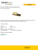
Essentia D
Wiring Diagram
Zone/Room 1 Zone/Room 2 Zone/Room 3 Zone/Room 4 Zone/Room 5 Zone/Room 6
Diagram shown with optional NuVo
NV-P2100 auxiliary amplifier powering
zone 6.
EZ Port Cat-5
connection
Single Network cable
connection to the
Essentia Amplifier
R
L
SENSITIVITY
OdBV = 1.0RMS
-12
+6
0
LEFT
+6
-12
RIGHT
0
AUDIO
INPUT
2
INPUT
OUTPUT
CONTROL
SPEAKER
MODELNV-P2100
HIGHEFFICIENCY 200 WATT
STEREOAMPLIFIER
NuVoTechnologies Cincinnati Ohio. USA
120V
60HZ
WATTS
250
UNIT
ON
+12VDC
100mA
VOLTAGE
TRIGGER
3-30 VOLTS
AC OR DC
ON/OFF SWITCH
AUDIO AC/DC
POWER
MODE
OUTPUT POWER
8 OHM: 70W X 2
4 OHM: 100W X 2
CONTROL
USE ONLYWITH 250V FUSE
USE ONLYWITH 250V FUSE
R
ZONE 6
SYSTEM
ZONE TRIGGEROUTPUTS
SOURCE LINK
SOURCE INPUTS
ZONE 1
NETWORK
EMITTER OUTPUTS
DIGITAL LINK
ZONE 3
ZONE 4
ZONE 5
ZONE 2
PROGRAM
RS-232
CONNECT TO
NV-I8X
USE NV-SLC1
CABLE
CONNECT TO
NV-I8EZP1
USE NV-NC1
CABLE
SYS ON
EXT. MUTE
SUM1
1
13
5
135
2
4
6
SUM2
5
24
6
CONNECT TO
NV-I8X
USE NV-SLC1
CABLE
12 34 5
6
12 34 5
6
OUTPUT POWER
OUTPUT POWER
OUTPUT POWER
OUTPUT POWER
OUTPUT POWER
OUTPUT POWER
20W/6OHM X2
20W/6OHM X2
20W/6OHM X2
20W/6OHM X2
20W/6OHM X2
20W/6OHM X2
VARIABLE
OUTPUT
VARIABLE
OUTPUT
VARIABLE
OUTPUT
VARIABLE
OUTPUT
VAR IABL E
OUTPUT
VAR IABLE
OUTPUT
FIXED
OUTPUT
FIXED
OUTPUT
FIXED
OUTPUT
FIXED
OUTPUT
FIXED
OUTPUT
FIXED
OUTPUT
TIP=L
RING=R
TIP=L
RING=R
TIP=L
RING=R
TIP=L
RING=R
TIP=L
RING=R
TIP=L
RING=R
O
O
O
O
N
N
N
N
O
O
O
O
F
F
F
F
F
F
F
F
A
A
A
A
L
L
L
L
L
L
L
L
O
O
O
O
F
F
F
F
F
F
F
F
CD1
CD1
CD1
CD1
CD2
CD2
CD2
CD2
TNR1
TNR1
TNR1
TNR1
TNR2
TNR2
TNR2
TNR2
TNR3
TNR3
TNR3
TNR3
SAT
SAT
SAT
SAT
VOLUME
VOLUME
VOLUME
VOLUME
ON
OFF
ALL
OFF
CD1
CD2
TNR1
TNR2
TNR3
SAT
VOLUME
ON
OFF
ALL
OFF
CD1
CD2
TNR1
TNR2
TNR3
SAT
VOLUME
5

Quick Start Guide
Your Essentia Audio Distribution System is quick and easy to install. This guide outlines the necessary steps for
an accurate and successful installation, and years of audio enjoyment.
Step 1:
Check your package for all of the components. Your box should contain the following items:
1 NV-E6DMS 6-source, 6-zone digital audio distribution amplifier
6 NV-E6DKPC keypads, with 1 bag of preprinted source buttons, ivory, and almond
replacement keypad inserts for each
1 NV-RC2 remote control with batteries
1 NV-NEC 10 foot network cable
1 NV-E6DEZP EZ Port connection hub
6 NV-VEC IR emitters
1 AC power cord
1 Installation manual
Step 2:
Place the Essentia amplifier in its preferred location. The Essentia amplifier is designed to be located in the cen-
tral media area where the home’s audio sources will be housed.
Step 3:
The Essentia amplifier should be turned on before any other cables are plugged in. This activates internal pro-
tective circuitry. Once the Essentia amplifier is turned on, it should be left on.
Step 4:
When the amplifier is in its location and turned on, the audio sources can be connected using stereo RCA cables.
These cables connect the left and right channels from the audio output of the source equipment to the appropri-
ate source input on the Essentia amplifier. The IR (infrared) emitters should be plugged into the IR outputs on
the back of the amplifier and attached to the IR window of the corresponding source equipment.
Step 5:
Each of the Cat-5 cables from the zones should be crimped with an RJ-45 connector using 568A or 568B wiring
(see page for Cat-5 crimping instructions). Test each Cat-5 connection using a cable tester before proceeding
with the installation. Each cable plugs into one of the RJ-45 connection jacks on the back of the supplied EZ Port.
It is important for future reference to label each cat-5 cable for its appropriate listening zone. The order in which
they are plugged into the EZ Port is irrelevant to the system’s operation.
Step 6:
Install the EZ Port in a standard dual gang low voltage bracket. We recommend the Carlon SC100R "Old Work
Bracket", or the SC100A "New Construction Bracket". These are designed for low voltage electronics and have an
open back for easy access to the back of the EZ Port.
6

Step 7:
Connect the provided pre-terminated network Cable in the RJ-45 connection jack on the front of the EZ Port and
in the Network Connection on the back of the Essentia amplifier.
Step 8:
Each zone is easily set using the DIP switches located on the back of the keypad. Switches 1-4 are used to set a
unique address for each zone and are noted with a "1" indicating the down position of the switch and a "O" indi-
cating the up position. Refer to the chart on the back of the keypad for the correct switch position for each zone.
Page 17 provides a visual reference of all of the available switch settings.
Step 9:
Switches 5, 6, & 7 are used to adjust the amount of bass and treble response in each zone. There are eight possi-
ble settings. The choices are a bass and treble boost, two levels of bass boost, two levels of treble boost, bass cut,
treble cut, or flat. The positions for these settings are also shown as "1" for down and "O" for up and are shown on
page 18.
Step 10:
Switch 8 allows multiple zones to share the same source. This is useful for large living spaces such as a kitchen,
breakfast nook, and dinning room where there are no walls defining each room. When switch 8 is in the up "O"
position, all keypads with the same setting will then always turn on at the same source. This does, however,
allow individual volume and on/off control. This setting is shown on page 18.
Step 11:
Switch 9 sets the volume level when the zone is turned on. The choices are to have the zone turn on at the same
level it was at when it was previously turned off (switch 9 in the down "1" position), or to turn on at a low volume
level (switch 9 in the up "O" position). This setting is shown on page 19.
Step 12:
Once the desired switch settings have been made for each keypad and they have been installed in their zone loca-
tions, you will be able to turn each zone on and off, control volume, and choose audio sources independently.
These functions can also be done wirelessly using the NuVo RC2 remote control. The built-in IR receiver in each
keypad also allows for direct control of the audio source equipment using that equipment’s remote control or a
universal learning remote control.
7

Essentia
Amplifier Front Panel
1. POWER Button: The amplifier is designed to be turned on and remain on. The power button
supplies power to the system. Each zone can then be turned on or off
independently. The amplifier should be turned on before any external connec-
tions are made. This activates internal protective circuitry. With all the zones
turned off the resulting "standby" power consumption is extremely low.
2. STAND BY LED: This blue LED (light-emitting diode) will indicate that the amplifier is plugged
in to an AC outlet source.
3. Zone Status LED’s: These LED’s indicate the power status of each zone. When a zone LED is lit,
that zone is currently turned on.
8
POWER
STAND BY
ZONE 1
ZONE 2
ZONE 3
ZONE 4
ZONE 5
ZONE 6
12 3

9
Essentia
Amplifier Back Panel
1. Audio Source Inputs: The Essentia amplifier accepts up to six audio sources. A source consists of any
audio component capable of supplying a line level signal.
2 Source Link: This multi-pin connection is used to transfer the audio information from the
Essentia main amplifier to the expander amplifier. This output is used along with
the Digital Link (11) to expand the system to twelve zones. The source link connec-
tion cable is provided with the Essentia D Expander package.
3. Variable Lineout: The variable lineout is intended for zones where additional amplification is needed
and the Essentia keypad is used to control the volume of all the speakers in that
zone.
4. Fixed Line Out: The fixed lineout is intended for zones where additional amplification and separate
volume control are needed.
5. Speaker Outputs: Individual stereo speaker outputs for each zone provide 20 watts output per chan-
nel.
6. Zone Triggers: These outputs provide a 12-volt output when the corresponding zone is turned on.
This is used to trigger external equipment specific to a given zone.
7. Emitter Outputs: These outputs transfer IR (infra red) signals, repeated from a zone keypad, from the
Essentia amplifier to the audio source equipment. There are six source specific out-
puts and two "sum" output that sends IR signals regardless of the selected source.
8. System On: This output provides a constant 12-volt output when any zone is turned on. This is
used to trigger external devices.
9. External Mute: This is designed to mute any audio playing through the system when the phone or
doorbell rings.
10. Network Input: This RJ-45 connection is the input for all zone information coming from the
Essentia keypads. The connection is made using the Network Cable supplied with
the package.
11. Digital Link: This multi-pin connection transfers all the digital information from the main ampli-
fier to the expander amplifier. This output is used along with the Source Link (2) to
expand the system from six to twelve zones. The Digital Link connection cable is
provided with the Essentia D Expander package.
12. RS232 Port: The RS232 serial port allows two-way communication for control by a home automa-
tion system.
13. AC: A detachable power cord connects the system to an external AC power supply.
R
ZONE 6
SYSTEM
ZONE TRIGGER OUTPUTS
SOURCE LINK
SOURCE INPUTS
ZONE 1
NETWORK
EMITTER OUTPUTS
DIGITAL LINK
ZONE 3
ZONE 4
ZONE 5
ZONE 2
PROGRAM
1
234
5
6
7 8
9
10
11
12
13
RS-232
CONNECT TO
NV-I8X
USE NV-SLC1
CABLE
CONNECT TO
NV-I8EZP1
USE NV-NC1
CABLE
SYS ON
EXT. MUTE
SUM1
1
1
3
5
135
2
4
6
SUM2
5
24
6
CONNECT TO
NV-I8X
USE NV-SLC1
CABLE
12 34 5
6
12 34 5
6
OUTPUT POWER
OUTPUT POWER
OUTPUT POWER
OUTPUT POWER
OUTPUT POWER
OUTPUT POWER
20W/6OHM X2
20W/6OHM X2
20W/6OHM X2
20W/6OHM X2
20W/6OHM X2
20W/6OHM X2
VARIABLE
OUTPUT
VAR I ABLE
OUTPUT
VARIABLE
OUTPUT
VARIABLE
OUTPUT
VARIABLE
OUTPUT
VARIABLE
OUTPUT
FIXED
OUTPUT
FIXED
OUTPUT
FIXED
OUTPUT
FIXED
OUTPUT
FIXED
OUTPUT
FIXED
OUTPUT
TIP=L
RING=R
TIP=L
RING=R
TIP=L
RING=R
TIP=L
RING=R
TIP=L
RING=R
TIP=L
RING=R

Essentia
Keypad
1. Volume Indicator: These LED’s (light emitting diodes) indicate the zones volume level. The lit
LED travels to the right as the volume level is increased and to the left as it is
decreased.
2. Volume Buttons: These buttons control the zone’s volume level up and down. They also serve
as the window for receiving IR commands from a remote control.
3. ON/OFF: This turns the individual zone on or off.
4. Source Selectors: These buttons select the desired audio source. Once selected that source but-
ton remains a backlit green until a new source is selected or the zone is
turned off. Each keypad ships with 36 preprinted source buttons.
5. ALL OFF: This turns all the zones off simultaneously.
6. Keypad Insert: Each of the Essentia keypads ship with white, ivory and almond color replace-
able Decora style inserts.
7. RJ-45 connection: Each keypad is connected to the Essentia amplifier via a Cat-5 wire and an
RJ-45 connection.
10
ON
OFF
ALL
OFF
CD1
CD2
TNR1
TNR2
TNR3
SAT
VOLUME
1
2
3
4
5
7
6

11
Essentia
RC2 Remote Control
1. IR Emitter: Use the RC2 remote’s IR emitter to directly control the Essentia System or to
teach the system control functions to any learning remote control.
2. Device Selectors: This allows you to easily switch between the NuVo Essentia System and any
of the NuVo Tuners.
3. Source Selectors: Change sources wirelessly.
4. ALL OFF Button: Turn off all the system keypads via IR command.
5. Zone ON/OFF Button: Individual zones may be turned on or off via IR.
6. Volume Button: Allows wireless control of the zone’s volume level.
11
12
3
4
7
8
9
5
6
0
NUM
MEM
VOL
VOL
OFF
ON
ALL OFF
ON- OFF
MON
ST
AM
FM
_
_
+
+
MULTI
ROOM
TUNER
TUNER 1
TUNER 3
MULTI
TUNER 2
NV-RC2
1
2
3
4
5
6

12
Installing Essentia in Your Home
I. Complete Crimping Instructions
for Cat-5 (Fig. 1)
The NuVo audio systems require Cat-5, unshielded,
twisted pair (UTP), for communication between the
keypads and the main amplifier unit. Each end of the
wire is terminated with an RJ45 connector.
The correct wiring scheme for the Cat-5 wire is stan-
dard EIA/TIA 568A, which is the industry standard for
computer networking. Properly terminating the Cat-5
wire is crucial for the operation of the system. It is
very important to use a good quality crimp tool, and
testing each termination with a Cat-5 wire tester will
insure that your system operates flawlessly.
Step-by-Step Crimping Instructions
1. Strip a 2 to 3 inch portion of the insulation, expos-
ing the 4 twisted pairs.
2. Untwist the wires and fan them out individually.
Arrange the wires into the correct color scheme.
Note that each of the wires is either a solid color, or
a white wire with a colored stripe. The colors are
green, orange, blue, and brown. The colors need to
be in the order shown in Fig. 1.
3. Flatten the wires in their correct order, and trim
them evenly across the top. Most crimp tools have a
wire trimmer built-in. It is best to trim the wires to
about 1/2" in length.
4. While holding the wires flat between your thumb
and forefinger, insert the wires into the RJ45 con-
nector, so each wire is in its own slot. Push the wire
into the RJ45, so all 8 conductors touch the end of
the connector. The insulation jacket should extend
beyond the crimp point of the RJ45.
5. Insert the RJ45 into the crimp tool receptacle and
squeeze the tool firmly. Note that a ratchet type tool
should tighten down until it no longer clicks.
6. The RJ45 should be firmly crimped to the Cat-5 insu-
lation. It is necessary that the color scheme be
repeated identically on each end of the wire.
Fig. 1: CAT-5 568A wiring scheme
Pin #
1. Green Stripe
2. Green
3. Orange Stripe
4. Blue
5. Blue Stripe
6. Orange
7. Brown Stripe
8. Brown
Note: Colors listed as “Stripe” are a white wire with a col-
ored stripe. In other words, Orange Stripe is a white wire
with orange stripes.
1
2
3
45 678
Pair 2
Pair 1
Pair 4
Pair 3
Ground
Serial Data Bus -
Serial Data Bus +
IR Signal
Ground
Plus 12V
Step 1
Step 2
Step 3
Step 4
Step 5
Step 6

13
II. Installing the Essentia Amplifier
System setup works best when the amplifier is placed
in the same location as the audio source equipment.
This is typically in an audio rack, entertainment center
or a closet dedicated to housing the home audio/video
equipment.
The amplifier should be plugged in and the power but-
ton on the front panel should be depressed before pro-
ceeding with the rest of the installation. This activates
the internal protective circuitry of the Essentia
System.
III. Installing the NV-E6DEZP EZ
Port (Fig. 2)
The EZ Port is a multi-connection hub designed to
accept all the Cat-5 wires from the keypads in the sys-
tem. The location of the EZ Port should be determined
by the location of the Essentia amplifier. It is best to
place in the wall behind the amplifier that would be
easily accessible if necessary.
The EZ Port fits easily in any dual-gang size construc-
tion bracket with an open back. These are often
referred to as "mud rings". Simply plug the terminated
Cat-5 wires into any of the sixteen available jacks on
the back of the EZ Port. The order in which the individ-
ual Cat-5 wires is plugged in not important, although it
is strongly recommended that you label the Cat-5 with
the appropriate zone number for future reference.
Once you have plugged the Cat-5 wires into the EZ
Port, screw the EZ Port into its construction bracket
using the supplied mounting screws.
Fig. 2

14
IV. Connecting the EZ Port to the
Essentia amplifier (Fig. 3)
When the EZ Port is installed in the wall the only part
visible should be the faceplate and a single RJ-45 jack.
The supplied pre-terminated network cable can then be
plugged into the jack on the EZ Port and into the net-
work connection on the back of the Essentia amplifier,
Any Cat-5 cable terminated using 568A or 568B net-
work wiring will suffice should you need a longer con-
nection.
V. Attaching Audio Source
Equipment to the Essentia
Amplifier (Fig. 4)
Each piece of audio source equipment is connected to
the Essentia amplifier with standard stereo RCA
cables. Attach the RCA cable to the corresponding
audio output on the source equipment and to the
desired source input on the back of the Essentia ampli-
fier.
Fig. 3
Fig. 4
SYSTEM
DIGITAL LINK
PROGRAM
CONNECT TO
NV-I6X
USE NV-SLC1
CABLE
CONNECT TO
NV-I6EZP1
USE NV-NC1
CABLE
SYS ON
EXT. MUTE
NETWORK
EZ Port
Essentia Network
Connection
Network Cable
SOURCE LINK
SOURCE INPUTS
ZONE 1
ZONE 3
ZONE 2
CONNECT TO
NV-I8X
USE NV-SLC1
CABLE
12 34 5
6
12 34 5
6
ZONE 1
ZONE 3
ZONE 2
OUTPUT POWER
OUTPUT POWER
OUTPUT POWER
20W/6OHM X2
20W/6OHM X2
20W/6OHM X2
VAR I ABLE
OUTPUT
VARIABLE
OUTPUT
VARIABLE
OUTPUT
FIXED
OUTPUT
FIXED
OUTPUT
FIXED
OUTPUT
TIP=L
RING=R
TIP=L
RING=R
TIP=L
RING=R
Source 1
Tuner 1
Audio
Out

15
VI. Connecting the IR Emitters
(Fig. 5)
IR commands for the source equipment are transferred
from the Essentia amplifier to the source equipment
via mini IR mouse emitters. Six of these are supplied
with your Essentia System. The emitter is plugged
into the corresponding source IR output on the
Essentia and then placed over the IR receiver window
on the source component. The IR outputs are individu-
ally routed to sources 1-6.
The two SUM outputs will flash any IR command that
is sent from any of the zones. This is used to connect
the NuVo T3 Tuner to the Essentia System or an IR
blaster designed to flash IR commands to a variety of
components. This is done by plugging a single mono
1/8" patch cable into the SUM IR output and into the
Direct IR input on the T3.
VII. Expanding Essentia to 12 Zones
(Fig. 6)
Six additional listening zones can be added to the
Essentia System using the Essentia Expander package.
The expansion is easily done using the Source Link
and Digital Link multi-pin outputs on the Essentia
main amplifier.
The necessary cables for this are supplied with the
Expander package. No other connections are necessary
with the exception of the AC power cord and the addi-
tional speaker terminations. The additional Cat-5
wires for the zones 7-12 plug into the EZ Port.
Fig. 5
Fig. 6
R
ZONE 6
SYSTEM
ZONE TRIGGEROUTPUTS
SOURCE LINK
SOURCE INPUTS
ZONE 1
NETWORK
EMITTER OUTPUTS
DIGITALLINK
ZONE 3
ZONE 4
ZONE 5
ZONE 2
PROGRAM
RS-232
CONNECT TO
NV-I8X
USE NV-SLC1
CABLE
CONNECT TO
NV-I8EZP1
USE NV-NC1
CABLE
SYS ON
EXT.MUTE
SUM1
1
1
2
3
123
4
5
6
SUM2
5
45
6
CONNECT TO
NV-I8X
USE NV-SLC1
CABLE
12 34 5
6
12 34 5
6
OUTPUT POWER
OUTPUT POWER
OUTPUT POWER
OUTPUT POWER
OUTPUT POWER
OUTPUT POWER
20W/6OHM X2
20W/6OHM X2
20W/6OHM X2
20W/6OHM X2
20W/6OHM X2
20W/6OHM X2
VARIABLE
OUTPUT
VARIABLE
OUTPUT
VARI ABLE
OUTPUT
VARI ABL E
OUTPUT
VARI ABLE
OUTPUT
VARI ABLE
OUTPUT
FIXED
OUTPUT
FIXED
OUTPUT
FIXED
OUTPUT
FIXED
OUTPUT
FIXED
OUTPUT
FIXED
OUTPUT
TIP=L
RING=R
TIP=L
RING=R
TIP=L
RING=R
TIP=L
RING=R
TIP=L
RING=R
TIP=L
RING=R
R
ZONE 12
ZONE TRIGGEROUTPUTS
SOURCE LINK
ZONE 71
DIGITALLINK
ZONE 9
ZONE 10
ZONE 11
ZONE 8
CONNECT TO
NV-I8X
USE NV-SLC1
CABLE
1
7
8
9
5
10 11
12
CONNECT TO
NV-I8X
USE NV-SLC1
CABLE
OUTPUT POWER
OUTPUT POWER
OUTPUT POWER
OUTPUT POWER
OUTPUT POWER
OUTPUT POWER
20W/6OHM X2
20W/6OHM X2
20W/6OHM X2
20W/6OHM X2
20W/6OHM X2
20W/6OHM X2
VARIABLE
OUTPUT
VARIABLE
OUTPUT
VARIABLE
OUTPUT
VARI ABLE
OUTPUT
VARIABLE
OUTPUT
VARIABLE
OUTPUT
FIXED
OUTPUT
FIXED
OUTPUT
FIXED
OUTPUT
FIXED
OUTPUT
FIXED
OUTPUT
FIXED
OUTPUT
TIP=L
RING=R
TIP=L
RING=R
TIP=L
RING=R
TIP=L
RING=R
TIP=L
RING=R
TIP=L
RING=R

16
VIII. Installing the Essentia keypads
(Fig. 7)
You are now ready to install the keypads and complete
the Essentia installation. This is easily done using a
series of DIP switches on the back of the keypad. A
chart on the back of the keypad shows each switch’s
function, and the setting options.
See page 17 for instructions on how to properly set the
nine DIP switches on each keypad.
Fig. 7: Keypad DIP switch chart
BLACK
RED
TO NV-LSI24
TO NV-LSI24
DOWN
UP
4b
3b
2b
1b
12
11
10
9
8
7
0000
1111
0111
1011
0011
1101
0101
1001
0001
1110
1000
0100
1100
0010
1010
0110
1
2
3
4
5
6
SW#
1,2,3,4
ZN#
SW#
5,6,7
000
100
010
110
001
101
011
111
EQ
B,T+4
TRB+8
TRB+4
TRB-4
BAS+8
BAS +4
BAS +4
BAS-4
FLAT
SW#
8
0
1
SRC
GRP
ON
OFF
SW#
9
VOL.RST
@ZN OFF
@ZN OFF
0
1
ON
OFF
0
1
"1" IS DOWN
"1" IS DOWN
SW1-4 SETS ADDRESS
SW1-4 SETS ADDRESS
SW5-7 SETS EQ
SW5-7 SETS EQ
SW8 SETS GROUP ON/OFF
SW8 SETS GROUP ON/OFF
SW9 SETS VOL. RST.
SW9 SETS VOL. RST.
NuVo
www.nuvotechnologies.com
www.nuvotechnologies.com
NV-E6DKYP
E6D KEYPAD
E6D KEYPAD
9
8
7
6
5
4
3
2
1
ON

IX. Setting the Zone Address DIP
Switches (Fig. 8)
The first four switches on the keypads are designed to
create a specific binary address identifying each zone
to the amplifier. Setting each zone address is easy, but
it is important to note that each keypad must have its
own unique setting.
Each switch can either be placed in an up or down posi-
tion. The chart on each keypad indicates the switch
position using a "1" for the switch in its down position,
and "0" for the switch in its up position. Thus, the set-
ting for Zone 1 is 1000, or switch #1 in the down posi-
tion and switches #2-4 in the up position.
Once each keypad is set for its zone, you should be able
to control volume, change the source selection, and
turn the zone on or off. The corresponding zone LED
on the face of the amplifier will turn on when the zone
keypad is turned on.
Additional Zone Keypads (Fig. 9)
The four additional addresses labeled 1B,2B,3B, and 4B
are used in zones 1-4 for an additional keypad in each
of those zones.
Fig. 8: Keypad Zone Address Switch Settings
Fig. 9: Keypad Zone Address Switch Settings
17
DOWN
UP
0
1
DOWN
UP
0
1
DOWN
UP
0
1
DOWN
UP
0
1
DOWN
UP
0
1
DOWN
UP
0
1
DOWN
UP
0
1
DOWN
UP
0
1
9
9
9
9
9
9
9
9
8
8
8
8
8
8
8
8
7
7
7
7
7
7
7
7
6
6
6
6
6
6
6
6
5
5
5
5
5
5
5
5
4
4
4
4
4
4
4
4
3
3
3
3
3
3
3
3
2
2
2
2
2
2
2
2
1
1
1
1
1
1
1
1
ON
ON
ON
ON
ON
ON
ON
ON
Zone 1
Zone 3
Zone 5
Zone 7
Zone 2
Zone 4
Zone 6
Zone 8
Switch 1 down Switches 2-4 up
Switches 1&2 down Switches 3&4 up
Switch1down Switch2up
Switch3down Switch4up
Switches 1-3 down Switch 4 up
Switch1up Switch2down
Switches 3&4 up
Switch 1&2 up Switch 3 down
Switches 4 up
Switch 1 up Switches 2&3 down
Switch 4up
Switches 1-3 up Switches 4 down
DOWN
UP
0
1
DOWN
UP
0
1
DOWN
UP
0
1
DOWN
UP
0
1
DOWN
UP
0
1
DOWNDOWN
UP
0
1
DOWN
UP
0
1
DOWN
UP
0
1
9
9
9
9
8
8
8
8
7
7
7
7
6
6
6
6
5
5
5
5
4
4
4
4
3
3
3
3
2
2
2
2
1
1
1
1
ON
ON
ON
ON
Zone 9
Zone 11
Zone 10
Zone 12
Switch 1 down Switches 2&3 up
Switch 4 down
Switches 1&2 down Switches 3 up
Switch 4 down
Switch1up Switch2down
Switches 3 upSwitch4down
Switch 1&2 up Switch 3&4 down
DOWN
UP
0
1
DOWN
UP
0
1
DOWN
UP
0
1
DOWN
UP
0
1
DOWN
UP
0
1
DOWN
UP
0
1
DOWN
UP
0
1
DOWN
UP
0
1
9
9
9
9
8
8
8
8
7
7
7
7
6
6
6
6
5
5
5
5
4
4
4
4
3
3
3
3
2
2
2
2
1
1
1
1
ON
ON
ON
ON
Zone 1B
Zone 3B
Zone 2B
Zone 4B
Switch 1 downSwitch2up
Switch 3&4
Switches 1-4 down
Switch 1 up Switches 2-4 down
Switches 1-4 up

18
X. Setting the Preset Zone
Equalization (Fig. 10)
Switches 5,6, and 7 are used to set equalizations for
each zone. These can be used to accommodate for
acoustical variations in each room. The switch settings
allow two levels of bass boost, two levels of treble
boost, or if necessary, bass or treble can be cut. If you
desire, you can leave the sound flat as it is recorded.
XI. Source Grouping (Fig. 11)
Switch 8 is used to set a source group. This is a useful
feature for large open living areas that do not have
defined spaces separated by walls. In these areas it is
not practical to have two or more sources playing at
the same time.
When a keypad has switch 8 in the up position, it will
share the same source selection as any other keypad in
the system that also has switch 8 in the up position.
This allows those zones to all play the same source
when turned on, but still maintain individual volume
control.
Fig. 10: Switches 5, 6, & 7 Zone EQ Settings
Fig. 11: Switch 8 Audio Source Grouping
DOWN
UP
0
1
DOWN
UP
0
1
DOWN
UP
0
1
DOWN
UP
0
1
DOWN
UP
0
1
DOWNDOWN
UP
0
1
DOWN
UP
0
1
DOWN
UP
0
1
9
9
9
9
9
9
9
9
8
8
8
8
8
8
8
8
7
7
7
7
7
7
7
7
6
6
6
6
6
6
6
6
5
5
5
5
5
5
5
5
4
4
4
4
4
4
4
4
3
3
3
3
3
3
3
3
2
2
2
2
2
2
2
2
1
1
1
1
1
1
1
1
ON
ON
ON
ON
ON
ON
ON
ON
Bass & Treble+4dB
Treble +4dB
Bass +8 dB
Bass -4 dB
Treble +8dB
Treble -4dB
Bass +4 dB
Flat
Switches 5, 6, & 7 up
Switch5up Switch6down
Switch7up
Switches5&6up Switch7down
Switch5up Switches6&7down
Switch5downSwitches6&7up
Switches5&6down Switch7up
Switch5down Switch6up
Switch7down
Switches 5, 6,&7down
DOWN
UP
0
1
DOWN
UP
0
1
9
9
8
8
7
7
6
6
5
5
4
4
3
3
2
2
1
1
ON
ON
Independent Source
Selection
Grouped Sources
Switch8down
Switch8up

19
XII. Volume Reset (Fig. 12)
Switch 9 controls the volume level when the zone is
turned on. When it is in the down position, the zone
will turn on at its previous volume level. When it is in
the up position, the zone will turn on at a preset low
volume level.
XIII. Parental Lock
A unique feature of the Essentia keypad is the ability
to lock the keypad functions once an audio selection is
made. This is done by pressing the button for the
selected source for approximately four seconds. The
keypad will flash indicating that it is locked. Once it is
locked it will not respond to any button pushes. To
unlock the keypad, simply press and hold the selected
source button again for approximately four seconds.
When the keypad flashes, it is then unlocked and will
then perform any of its functions.
Fig. 12: Switch 9 Audio Volume Reset
DOWN
UP
0
1
DOWN
UP
0
1
9
9
8
8
7
7
6
6
5
5
4
4
3
3
2
2
1
1
ON
ON
Previous Volume Level Reset to Low Level Volume
Switch 9 down
Switch9up

20
XIII. The NV-RC2 IR Remote Control
(Fig. 13)
The Essentia System comes with the RC2 remote con-
trol. This remote allows wireless control of all of the
keypad functions, as well as the functions of the NuVo
T3 Tuner. The four-backlit buttons at the top of the
remote allow you to choose which device the remote
will control. The numeric keypad is used to choose the
desired audio source, or tuner preset.
The RC2 remote is an ideal tool for teaching the NuVo
System functions to a universal learning remote con-
trol that can then operate the Essentia system as well
as all the individual source functions.
XIV. Changing the Buttons on the
Essentia Keypad (Fig. 14)
The Essentia keypads ship with 36 preprinted inter-
changeable source buttons. This allows you to easily
customize each keypad to match the audio components
being used in the system.
To change the buttons use a small screwdriver to
remove the outer Decora insert. This exposes two inner
plates that hold the buttons in place. Those are also
removed with a small screwdriver, allowing you to
remove and replace the desired source buttons.
Line up the tabs on the replacement buttons with the
corresponding holes in the keypad’s circuit board.
Once the new buttons are in place return the inner
plates and the outer keypad insert.
Fig. 13: NV-RC2 IR Remote Control
Fig. 14
NV-RC2 Remote Learning Remote
ON
OFF
ALL
OFF
CD1
CD2
TNR1
TNR2
TNR3
SAT
VOLUME
LED12
LED13
LED14
LED15
LED16
LED17
LED18

21
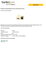
Essentia Accessories
NV-MI1 Mute Interface Adapter (Fig. 15)
The Mute Interface is used in conjunction with System Mute input in the back of the Essentia amplifier. It acts
as a relay for a voltage from up to two phone lines and two doorbell transformers. When a voltage is presented to
the MI1 it then sends a contact closure to the Essentia System, which in turn causes the system to mute momen-
tarily. This is useful in allowing the telephone ring or doorbell to be heard when audio is playing in any of the
zones.
MUTE INTERFACE
ADAPTER
NV-MI1
CONNECT TO
MUTE INPUT
A
B
A
B
DOORBELL 1
DOORBELL 2
Connect to Telephone RJ-11
Line 1: Pins 3,4 Line 2: Pins 2,5
Mute Interface Module
Model NV-MI1
R
OUTPUT POWER
OUTPUT POWER
20W/6OHM X2
20W/6OHM X2
SYS ON
EXT. MUTE
L
R
L
R
L
R
VARIABLE
OUTPUT
FIXED
OUTPUT
SUM1
3033118
C
US
CONFORMS TO
UL STD.6500
CERTIFIED TO
CAN/CSA STD.E60065
NuVoTechnologies CincinnatiOhio USA
FUSE:T5A
120V 60Hz 500W
MODEL NV-6DM
SIX SOURCESIX ZONE
AUDIO DISTRIBUTIONSYSTEM
www.nuvotechnologies.com
OUTPUT POWER
OUTPUT POWER
OUTPUT POWER
20W/6OHM X2
20W/6OHM X2
20W/6OHM X2
TIP=L
RING=R
VARIABLE
OUTPUT
FIXED
OUTPUT
TIP=L
RING=R
VARIABLE
OUTPUT
FIXED
OUTPUT
TIP=L
RING=R
VARIABLE
OUTPUT
FIXED
OUTPUT
TIP=L
RING=R
VARIABLE
OUTPUT
FIXED
OUTPUT
TIP=L
RING=R
VARIABLE
OUTPUT
FIXED
OUTPUT
TIP=L
RING=R
12 34 5
6
12 34 5
6
13
5
135
RS-232
CONNECT TO
NV-I8X
USE NV-SLC1
CABLE
CONNECT TO
NV-I8X
USE NV-SLC1
CABLE
CONNECT TO
NV-I8EZP1
USE NV-NC1
CABLE
USE CNLY WITH 250V FUSE
2
4
6
SUM2
24
6
OUTPUT POWER
20W/6OHM X2
ZONE 6
ZONE 6
SYSTEM
ZONE TRIGGER OUTPUTS
SOURCE LINK
SOURCE INPUTS
ZONE 1
NETWORK
EMITTER OUTPUTS
DIGITAL LINK
ZONE 3
ZONE 4
ZONE 5
ZONE 2
PROGRAM
Fig. 15: NuVo NV-MI1 Mute Interface for Use
With All NuVo Audio Distribution Systems
/