Planet SGSW-4802 User manual
- Category
- Network switches
- Type
- User manual

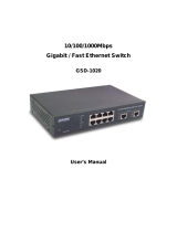
10/100/1000Mbps
Managed Stackable Switch
SGSW-4802
User’s Manual

Trademarks
Copyright PLANET Technology Corp. 2003.
Contents subject to revision without prior notice.
PLANET is a registered trademark of PLANET Technology Corp. All other trademarks belong to
their respective owners.
Disclaimer
PLANET Technology does not warrant that the hardware will work properly in all environments and
applications, and makes no warranty and representation, either implied or expressed, with respect to
the quality, performance, merchantability, or fitness for a particular purpose.
PLANET has made every effort to ensure that this User’s Manual is accurate; PLANET disclaims
liability for any inaccuracies or omissions that may have occurred.
Information in this User’s Manual is subject to change without notice and does not represent a
commitment on the part of PLANET. PLANET assumes no responsibility for any inaccuracies that
may be contained in this User’s Manual. PLANET makes no commitment to update or keep current
the information in this User’s Manual, and reserves the right to make improvements to this User’s
Manual and/or to the products described in this User’s Manual, at any time without notice.
If you find information in this manual that is incorrect, misleading, or incomplete, we would appreciate
your comments and suggestions.
FCC Warning
This equipment has been tested and found to comply with the limits for a Class A digital device,
pursuant to Part 15 of the FCC Rules. These limits are designed to provide reasonable protection
against harmful interference when the equipment is operated in a commercial environment. This
equipment generates, uses, and can radiate radio frequency energy and, if not installed and used in
accordance with the Instruction manual, may cause harmful interference to radio communications.
Operation of this equipment in a residential area is likely to cause harmful interference in which case
the user will be required to correct the interference at his own expense.
CE Mark Warning
This is a Class A product. In a domestic environment, this product may cause radio interference, in which
case the user may be required to take adequate measures.
Revision
PLANET Managed Stackable Switch User's Manual
FOR MODEL: SGSW-4802
REVISION: 1.0
Part No.: EM-SGSW4802V1

TABLE OF CONTENTS
1. Introduction.........................................................................................................................................1
1.1 Checklist..........................................................................................................................................1
1.2 About the Switch..............................................................................................................................1
1.3 Features..........................................................................................................................................1
1.4 Specification....................................................................................................................................2
2. Hardware Description.........................................................................................................................4
2.1 Front Panel......................................................................................................................................4
2.2 Rear Panel.......................................................................................................................................5
2.3 Hardware Installation.......................................................................................................................5
2.4 Terminal Setup................................................................................................................................5
2.5 IP Configuration...............................................................................................................................6
3.Web-based management.....................................................................................................................8
3.1 Configuration...................................................................................................................................8
3.2 Web Pages......................................................................................................................................9
3.3 Port Config.......................................................................................................................................9
3.4 VLAN Config..................................................................................................................................11
3.5 Trunk config...................................................................................................................................12
3.6 Advanced Configuration................................................................................................................13
3.7 STP Config....................................................................................................................................13
3.7.1 STP Port.................................................................................................................................14
3.7.2 STP Bridge..............................................................................................................................15
3.8 IGMP..............................................................................................................................................16
3.8.1 IGMP Management.................................................................................................................16
3.8.2 Definition on IGMP v1.0 and v2.0...........................................................................................16
3.9 Stack..............................................................................................................................................17
3.10 SNMP..........................................................................................................................................20
3.11 RMON Statistics..........................................................................................................................21
3.12 Port Security................................................................................................................................22
3.12.1 Setting Up Procedures..........................................................................................................22
3.12.2 Delete MAC Address............................................................................................................23
3.13 Mirror Port....................................................................................................................................24
3.13.1 Using Mirror Port to Monitor Traffic.......................................................................................24
3.13.2 Setup Procedures.................................................................................................................24
3.14 Aging Control...............................................................................................................................25
3.15 Address Search...........................................................................................................................25
3.15.1 Host Searching Procedures..................................................................................................26
3.15.2 MAC Address Search...........................................................................................................27
3.16 System Tools...............................................................................................................................28
3.17 System Config.............................................................................................................................28
3.18 System Information......................................................................................................................29
3.19 Change Password.......................................................................................................................30
3.20 Firmware Upgrade.......................................................................................................................31

3.21 Save & Reboot.............................................................................................................................34
3.21.1 Save......................................................................................................................................34
3.21.2 Backup..................................................................................................................................34
3.21.3 Restore.................................................................................................................................36
3.21.4 Clear and Reset....................................................................................................................37
3.22 Message Windows......................................................................................................................38
3.23 Reboot Switch..............................................................................................................................39
3.24 Logout..........................................................................................................................................39
4 Console interface...............................................................................................................................41
4.1 CONNECT TO PC.........................................................................................................................41
4.2 Logging on to the Switch...............................................................................................................42
4.2.1. sys--System Management Commands..................................................................................45
4.2.2 logout......................................................................................................................................55
4.2.3 port--Port Management Commands.......................................................................................55
4.2.4. vlan--VLAN Management Commands...................................................................................61
4.2.5 trunk--TRUNK Management Commands................................................................................63
4.2.6. stp--STP Management Commands.......................................................................................64
4.2.7 snmp--SNMP Management Commands.................................................................................68
4.2.8 stack--STACK Management Commands................................................................................70
4.2.9 igmp--IGMP Management Commands...................................................................................71
5. Switch Operation...............................................................................................................................73
5.1 Address Table...............................................................................................................................73
5.2 Learning.........................................................................................................................................73
5.3 Forwarding & Filtering....................................................................................................................73
5.4 Store-and-Forward........................................................................................................................73
5.5 Auto-Negotiation............................................................................................................................73
6. Troubleshooting................................................................................................................................74
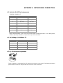
Appendix A Networking Connection...................................................................................................75
A.1 Switch‘s RJ-45 Pin Assignments...................................................................................................75
A.2 10/100Mbps, 10/100Base-TX.......................................................................................................75
A.3 RJ-45 cable pin assignment..........................................................................................................75

1
1. INTRODUCTION
1.1 Checklist
Check the contents of your package for following parts:
l SGSW-4802.
l User's manual CD.
l Power cord.
l 19” rack mounting kit.
l RS-232 cable.
l Quick Installation Guide.
If any of these pieces are missing or damaged, please contact your dealer immediately, if possible,
retain the carton including the original packing material, and use them against to repack the product in
case there is a need to return it to us for repair.
1.2 About the Switch
The SGSW-4802 Managed stackable Switch is designed to provide your network with Ethernet, Fast
Ethernet, Gigabit Ethernet connectivity over twisted pair and fiber optic cabling.
Two expansion slots on the front panel of the SGSW-4802 Managed Switch further add to the flexibility
of the systems.
The SGSW-4802 Managed Switch is a combination of 48x10/100M Ethernet RJ-45 ports and 2 op-
tional module slots.
The two optional modules can be 1-Port 100 Base-FX Managed Fiber Modules, Gigabit 1000Base-T
Managed Switch Modules, and Gigabit 1000Base-SX/LX Managed Fiber Modules.
With its build-in Web-based Management, managing and configuring the SGSW-4802 Managed
Switch becomes easier.
From cabinet management to port-level control and monitoring, you can visually configure and
manage your network via Web Browser, just click your mouse instead of typing cryptic command
strings. However, the SGSW-4802 Managed Switch can also be managed via Console, or third-party
SNMP Management.
1.3 Features
◆ Complies with the IEEE802.3 Ethernet, IEEE802.3u Fast Ethernet, IEEE802.3z and IEEE802.3ab
Gigabit Ethernet standard
w Provide 2 module slots for 100Mbps-FX, 1000Mbps-T or 1000Mbps-SX/LX option of modules
w Features Store-and-Forward mode with wire-speed filtering and forwarding rates
w Auto-negotiation & Full-duplex/Half-duplex
w Automatic source address learning and aging
w Support up to 8K MAC address
w Support IEEE802.1D Spanning Tree Protocol
w IEEE802.3x compliant full-duplex flow control
w Broadcast storm control, runt and CRC Filtering eliminates erroneous packets to optimize the
network bandwidth
w Stack up to 16 units
w LED indicators for simple diagnostics and management

2
w Internal power supply
w Auto MDI/ MDI-X on each port
w Network management configuration:
− Web-based management
− Console and Telnet Configuration
− SNMP network management
− IEEE 802.1Q Tagging VLAN (32 VLAN Groups)
− Port Trunking supported
− IEEE 802.1D Spanning Tree Protocol (STP)
− IGMP and Sniffer (Port Mirroring) supported
− Port Priority - 802.1p supported
− MAC / IP Address search
− Port security control (MAC address filtering)
− Virtual stacking up to 16 units
− Broadcast Storm Filter function supported
− Firmware upgradeable through Web interface
1.4 Specification
Product
SGSW-4802
10/100/1000Mbps Managed Ethernet Stackable Switch
Hardware Specification
Ports 48 10/ 100Base-TX RJ-45 Auto-MDI/MDI-X ports
Module Slot 2 for 1000Base-SX/LX/T and 100Base-FX modules
Stack Interface Through Ethernet interface. Up to 16 units can be managed by single IP
Switch Processing Scheme Store-and-forward
Throughput (packet per second)
10Mpps
Switch Fabric 9.6Gbps
Address Table 8K entries (4K for each 24-port)
Queue Buffer 12Mbytes (6Mbytes for each 24-port)
Flow Control Back pressure for half duplex, IEEE 802.3x Pause Frame for full duplex
Broadcast Storm Control Discards broadcast packets at a critical threshold
Dimensions 432 x 240 x 87 mm, 2U high
Weight 6.2 kg
Power Requirement 100~240 VAC, 50-60 Hz
Power Consumption / Dissipation
100 Watts maximum / 341 BTU/hr maximum
Temperature Operating: 0~40 degree C, Storage -20~70 degree
Humidity Operating: 10% to 90%, Storage: 5% to 90% (Non-condensing)
Network Management
System Configuration Console port, Web browser, SNMP/RMON
Management Agent SNMP Support: MIB II, Ethernet MIB, Repeater MIB and RMON MIB
Spanning Tree Algorithm IEEE 802.1D provides redundant link support

3
VLAN IEEE 802.1Q VLAN, up to 32 VLANs supported
QoS
IEEE 802.1p QoS support with 2 priority queue using WFQ (Weighted Fair
Queuing)
IGMP Multicast Filtering Passive snooping on IGMP Query/Report messages
Port trunking Up to 4 ports can be combined into a fat pipe
Port Mirroring 1 mirroring port to monitor several mirrored ports
Standards Conformance
Regulation Compliance FCC Part 15 Class A, CE
Standards Compliance
IEEE 802.3 (Ethernet)
IEEE 802.3u (Fast Ethernet),
IEEE 802.3z (1000Base-SX/LX), IEEE 802.3ab(1000Base-T),
IEEE 802.1D (STP),
IEEE 802.3x (full-duplex flow control),
IEEE 802.1p (QoS),
IEEE 802.1Q (VLANs)
RFC 768 UDP
RFC 783 TFTP
RFC 791 IP
RFC 792 ICMP
RFC 826 ARP
RFC 1122 Host Requirements
RFC 2068 HTTP
RFC 2236 IGMP v2
RFC 1157 SNMP v1/v2
RFC 1213 MIB II
RFC 1643 Ethernet MIB

4
2. HARDWARE DESCRIPTION
This product series provide three different running speed – 10Mbps, 100Mbps, and 1000Mbps in the
same switch and automatically distinguish the speed of incoming connection.
This section describes the hardware features of SGSW-4802. For easier management and control of the
switch, familiarize yourself with its display indicators, and ports. Front panel illustrations in this chapter
display the unit LED indicators. Before connecting any network device to the switch, read this chapter
carefully
There are following option module for expansion:
l 1-Port 100Base-FX Managed Fiber Module (SC/ST, Multi-mode fiber)
l 1-port 100Base-FX Fast Ethernet Module (SC, Single-mode fiber, 15km)
l 1-Port Gigabit 1000Base-T Managed Switch Module
l 1-Port Gigabit 1000Base-SX/LX Managed Fiber Module
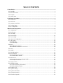
2.1 Front Panel
The Front Panel of the SGSW-4802 Managed Switch consists of 48x auto-sensing 10/100Mbps
Ethernet RJ-45 Ports, two optional expansion slots, and Console port. The LED Indicators are also
located on the front panel of the Switch.
Console
38400, 8, N, 1
1357
2468
9111315
10121416
17192123
18202224
41434547
42444648
33353739
34363840
25272931
26283032
49
50
SGSW-4802 Switch front panel
2.1.1 LED indicators
SGSW-4802
PWR Green Lit on: Power on
Lit off: power off
Link Green Lit on: the connection is good
Lit off: the port is disabled or not detecting a link
Mode: (could be three kinds of meaning, varies with the Mode button)
ACT Green Lit on: the connection is good.
Blink: The port is receiving or transmitting data
FDX
Green Lit on: the port run at full-duplex
Blink: Half-Duplex/ Collision
Off: Half-duplex or not connected
100 Green Lit on: run at 100Mbps
Lit off: run at 10Mbps or not connected
2.1.2 Buttons indicators
SGSW-4802
RESET When press this button, Switch will reboot
MODE Hold the button for at least 5 seconds, the LED will turns to the next LED in
cycle. (ACT àFDXàSpeedàACT)

5
2.2 Rear Panel
The rear panel of the Switch indicates an AC inlet power socket, which accepts input power from 100
to 240VAC, 50-60Hz.
100-240VAC
50/60Hz
SGSW-4802 Switch rear panel
Power Notice:
1. The device is a power-required device, it means, it will not work till it is powered. If your networks
should active all the time, please consider using UPS (Uninterrupted Power Supply) for your de-
vice. It will prevent you from network data loss or network downtime.
2. In some area, installing a surge suppression device may also help to protect your switch from
being damaged by unregulated surge or current to the Switch or the power adapter.
2.3 Hardware Installation
2.3.1 Connecting end node or hub or switch
1. Place the Switch on a smooth surface or fasten the mounting brackets with the provided screws in a
standard 19” rack.
2. Connect switch or PC to one port of the Switch using Category 3/4/5 UTP/STP cabling.
3. Connect another switch or PC to the other port of Switch by following the same process as described
in Step2.
Notice:
Cable distance for Switch
The cable distance between Ethernet Switch and hub/PC should not exceed 100 meter for
UTP/STP cable, 2km for 62.5/125 and 50/125 fiber cable on 100Base-FX module, 220m for
62.5/125 fiber cable and 500m for 50/125 fiber cable on 1000Base-SX module, 550m for 62.5/125
and 50/125 fiber cable and 10km for 9/125 fiber cable on 1000Base-LX module.
Make sure the wiring is correct
It can be used Category 3/4/5 cable in 10 Mbps operation. To reliably operate your network at
100Mbps and 1000Mbps, you must use an Unshielded Twisted-Pair (UTP) Category 5 cable, or
better Data Grade cabling. While a Category 3 or 4 cable may initially seem to work, it will soon
cause data loss.
2.3.2 Connecting to Network Backbone or Server
Connect to the Gigabit Ethernet ports with Category 5 copper cable or fiber optic cable for uplinking to
a network backbone or network server. These ports operate at 1000Mbps in full-duplex mode. A valid
connection is indicated when the Link LED is light.
2.4 Terminal Setup
To configure the system, connect a serial cable to a COM port on a PC or notebook computer and to
serial (console) port of the device. The console port of the device is DCE already, so that you can
connect the console port directly through PC without the need of Null Modem.
A terminal program is required to make the software connection to the device. Windows’ Hyper Ter-

6
minal program may be a good choice. It can be accessed from the Start menu. Click START, then
Programs, Accessories and then Hyper Terminal.
MS-DOS based terminal program such as PC-PLUS, PROCOMM, can also make the connection with
the device built-in software. The COM port should be configured as:
♦ Baud : 38400
♦ Parity : None
♦ Data bits : 8
♦ Stop bits : 1
♦ Flow Control: none
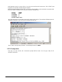
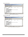
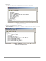
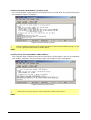
Once the terminal has connected to the device, power on the device. The terminal will display that it is
loading the firmware. Then, the screen as below will show up:
Press “Enter” and input the password. The default password is “admin”.
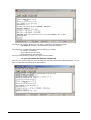
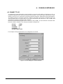
2.5 IP Configuration
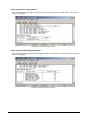
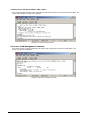
Once log on to the console, the “Command>” prompt will be shown. You can type, “help” for all
available commands.

7
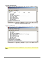
To setup the IP address, please use “sys set ip” command in the following format:
sys set ip <IP Address> <Subnet Mask> <Default Gateway>
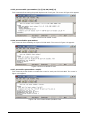
For example, to configure the switch with the following IP settings:
IP Address: 192.168.0.2
Subnet Mask: 255.255.255.0
Default Gateway: 192.168.0.254
Press input the following command and press <Enter> button:
sys set ip 192.168.0.2 255.255.255.0 192.168.0.254
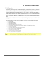
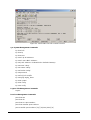
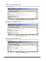
If the IP is successful configured, the switch will automatically restart as the following window. You can
then configure the switch through its web interface.

8
3. WEB-BASED MANAGEMENT
3.1 Configuration
As well as the menu-driven system configuration program, the agent module provides an embedded
HTTP Web agent. This agent can be accessed by any computer on the network that using a standard
Web browser (Internet Explorer 5.0 or above, or Netscape Navigator 4.5 or above).
Using the Web browser management interface you can configure a switch and view statistics to
monitor network activity. The Web interface also provides access to a range of SNMP management
functions with access to the switch's MIB and RMON database.
Prior to accessing the switch from a Web browser, be sure you have first performed the following
tasks:
Configure it with a valid IP address, subnet mask, and default gateway using an out-of-band serial
connection.
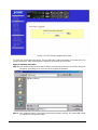
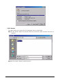
For Internet Explorer 5.0 or later version user, please check the Java setting below before startup.
1. Click on Tools
2. Pick Internet Options
3. Select the Security tab
4. Select Local Intranet (click on the icon)
5. Click on Sites, click Advanced and add the IP address of the switch to the zone
6. Click on Custom Level
7. Scroll down and set Java Permissions to Custom
8. Press the Java Custom Settings button
9. Select the Edit Permissions tab
10. Set Run Unsigned Content to Enable
11. Press OK for all open dialog windows
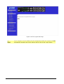
!
NOTE
For IE5.0 or later version, if you can not find the Java option in point 7
, please make sure your
Ethernet Explorer is installed with “Microsoft VM” JAVA virtual-machine plug-in.

9
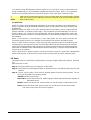
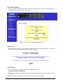
3.2 Web Pages
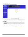
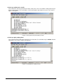
To access the Web-browser interface you must first enter the password. The default password is
"admin" You will see the following screen comes out on the Web browser program:
Figure 3-1: SGSW-4802 login Web Page
After the password is entered you will see the main menu web screen of SGSW-4802.
Figure 3-2: The start up screen of SGSW-4802 Web Page
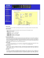
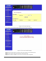
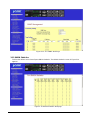
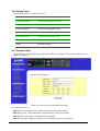
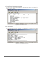
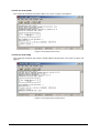
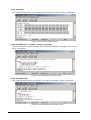
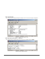
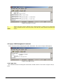
3.3 Port Config
This section allows you to have an easy access in configuring the ports of the management Switch.
Notice that the “Link state” option indicates “Up”. This shows that the port is connected to the network.
It can either be in “Up” (Connected) or “Down” (No connection) state.

10
Figure 3-3: The Port Config Web Page
Choose Port
You can choose a port either by clicking on the picture or by selecting it at the “Choose Port” field.
Speed/ Duplex
Speed/ Duplex is to select the operation mode of chosen port. The options are as:
‘Auto’: Auto negotiation
‘10Mbps HD’: 10 Base-T Half Duplex
‘10Mpbs FD’: 10Base-T Full Duplex
‘100Mpbs HD’: 100Base-TX Half Duplex
‘100Mbps FD’: 100Base-TX Full Duplex
Broadcast Rate Limit
This function sets broadcast limit to the desired rate for the specified port. It controls the reception of
broadcasting packets. The ranging for Broadcast rate limit varies from 0% to 100%. The higher the
rate is, the more broadcast packets can pass through the port. Rate is the percent of the traffic to
allow before throttling. That is, if you configure this value to 10% and current connected speed are
100M, Only 10M broadcast data can pass through the port.
Port Priority
In a tagged VLAN application, you can specify the VLAN priority to expedite the VLAN traffic. There
are 8 levels of priority, namely ‘0’, ‘1’, ‘2’, ‘3’, ‘4’, ‘5’, ‘6’ and ‘7’ in ascending priority.
Port VLAN ID
VLAN ID is the sequence number of a VLAN. The setting of the VLAN ID depends on ‘Belongs to
VLANs’ option. Thus, you should first configure the VLAN table through “VLAN config” option and
then specify this value.
Port State
Port state is for enabling or disabling the switch operation of the chosen port. If it is ‘enabled’, the
chosen port will receive and forward the packets, and learns the respective source MAC Addresses.
If it is ‘disable’, the chosen port will not receive or forward any packets or learn source MAC Ad-

11
dresses.
It should be noted that if the cpu port (i.e. the switch port connected to the management workstation)
is disabled, without doubt, the communication link between user and the switch will not proceed
further. It is recommended to locate the link your PC used before disable the port state.
Flow Control
This feature enables or disables the Flow Control function of the port. Flow control can eliminate
frame loss by "blocking" traffic from end stations or segments connected directly to the switch when
its buffers fill. IEEE 802.3x flow control is used for full duplex. Note that flow control should not be
used if a port is connected to a hub.
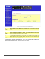
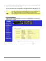
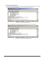
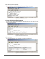
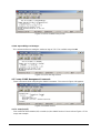
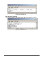
3.4 VLAN Config
The SGSW-4802 supports Virtual LAN, which logically groups the connection into VLANs for traffic
isolation and security purposes. Both tagged and untagged based VLAN are supported with a total
maximum of 32 groups. Each VLAN group only forwards traffic within its member ports. For tagged
VLAN, each port can be a member of more than one VLAN group and it also supports priority with eight
levels. There is also provision for creating an untagged VLAN, which support a connection with a
legacy untagged port. The VLAN configuration feature also allows you to build, delete and view tagged
/ untagged VLAN groups and setting priority for tagged VLANs. The range of VID starts from 3 to 4091,
as VID 001 and VID 002 is the default for Group 1 and Group 2.
Figure 3-4: The VLAN config Web Page
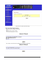
Setup Procedures
Step 1: Decide which Group you want to set for monitoring using mirror port. Click status column for
that particular group and key in the VLAN ID.
Step 2: Next, click on the dashed line’-‘ to select either “T” for Tagged or “U” for Untagged.
Step 3: Click “Apply” button after you satisfied with the setup. Click “Save” button to update the current
configuration.

12
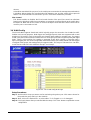
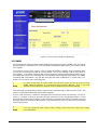
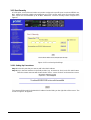
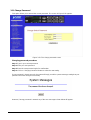
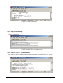
3.5 Trunk config
The SGSW-4802 provides 2 trunk groups and maximum up to 4-ports per trunk. Port Trunking is the
ability to group together several switch ports to increase the bandwidth between the management
switch and other switch. This is an inexpensive method to increase throughput between switches (or to
servers). We define the Port Trunking as the ability to group a set of ports into a single logical link. The
port trunk acts as single link between switches. It doesn’t create a loop even though it is physically
connected as such.
Figure 3-5: The Port Trunk config Web Page
Port Trunking Setup Procedures
Step 1: Decide to create a trunk group from port 1-24 or port 25-48.
Step 2: You can choose up to 4-port for Trunking by selecting ‘-‘ as “T”.
Step 3: Click on “Apply” button to make the configuration effective.
Step 4: Click “Save” button to save the current configuration.
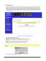
!
NOTE
If you select more than 4 ports for trunking, the following error message will appear:
Click “OK” button and select the ports again.

13
3.6 Advanced Configuration
The available options in “Advanced menu” are:
STP Config The Spanning Tree Setup Screen
IGMP Config The IGMP Setup Screen
Stack Config The Stack Setup Screen
SNMP Config The SNMP Setup Screen
RMON Statistics Show RMON statistics information
Port Security The Port Security Setup Screen
MirrorPort Config The Mirror Port Setup Screen
Aging Control The Aging Control Setup Screen
Address Search The Address Search Setup Screen
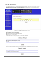
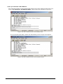
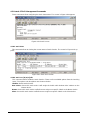
3.7 STP Config
The STP Config provides two-menu pages to configure: STP Port and STP Bridge. The STP screen in
Figure 3-6 appears.
Figure 3-6: The STP Port Web Page

14
3.7.1 STP Port
This function allows assigning Path Cost value and Priority level on each port of SGSW-4802.
Please refer to the detail description of Path Cost and Priority and setup procedures shown as
below.
Description of Parameters
Bridge Port
This option shows the port of the bridge that connects to the root bridge.
Path Cost
The STA algorithm to determine the best path between devices uses this parameter. Therefore,
lower values should be assigned to ports attached to faster media, and higher values assigned to
ports with slower media. (Path cost takes precedence over port priority.)
The default and recommended range is: Ethernet: 100 (50~600) Fast Ethernet: 19 (10~60) Gigabit
Ethernet: 4 (3~10). The allowed range is 0 - 65535.
Priority
Defines the priority for the use of a port in the Spanning Tree algorithm. If the path cost for all ports
on a switch are the same, the port with the highest priority (i.e., lowest value) will be configured as
an active link in the Spanning Tree. Where more than one port is assigned the highest priority, the
port with lowest numeric identifier will be enabled. The range is 0 - 255.
Setup Procedures
Step 1: Select any one of the ports, from 1 to 50, to connect to the root bridge.
Step 2: Key in the value for Path Cost.
Step 3: Set the priority level.
Step 4: Click “Apply” button after you satisfied with the setup. Click “Save” button to save the current
configuration.
!
NOTE
Due the hardware restriction, the STP function cannot across between port 1-24, slot 49
and port 25-48, slot 50.

15
3.7.2 STP Bridge
This function provides to have a clearer view in Spanning Tree parameters of SGSW-4802. The STP
Bridge screen in Figure 3-7 appears.
Figure 3-7: The STP Bridge Web Page
Description of Parameters
STP State
When STP is enabled, it will dynamically detect network looping owing to mis-configuration of the
network topology. The redundant connectors will be disabled to avoid looping of packets. Looping
would often result in flooding of broadcast packets, halting the normal traffic.
Root Priority
Device priority is used in selecting the root device, root port, and designated port. The device with
the highest priority becomes the STA root device. However, if all devices have the same priority,
the device with the lowest MAC address will then become the root device. The available range is
0-65535 sec.
Hello Time
The Hello time of the Spanning Tree field shows the number of seconds between the transmis-
sions of Spanning Tree protocol configuration messages. The available range is 1-10 sec.
Forward Delay
The Forward Delay field shows the number of seconds a port waits before changing from its
Spanning Tree Protocol learning and listening states to the forwarding state. This waiting is nec-
essary so that other switches on the network ensure no loop is formed before they allow other port
to forward packets.
The available range is 4-30 sec.
Max Age
The maximum age time of the Spanning Tree shows the number of seconds the bridge waits
without receiving Spanning Tree Protocol configuration message before attempting a reconfigu-
ration. The available range is 6-40 sec.

16
Setup Procedures
Step 1: Select Spanning Tree state option, either to enable or disable it.
Step 2: Set Root Priority from 0 s – 65535 s, and Hello Time from 1 s – 10 s.
Step 3: Key in the Forward Delay Time, Maximum Age and Hello Time.
Step 4: Click “Apply” button and save it if everything is OK.
!
NOTE
The screen is divided into two sections. Current Spanning
Tree Root section displays the
read-
only Spanning Tree settings for the current root switch and the parameters this
switch is to use when it becomes the root switch.
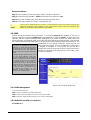
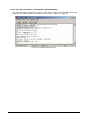
3.8 IGMP
Internet Group Management Protocol (IGMP) is an Internet protocol that provides a way for an
Internet computer to report its multicast group membership to adjacent routers. It allows the man-
agement switch to forward multicast traffic intelligently. The switch "snoops" the IGMP query and
report messages and forwards traffic to only the ports that request the multicast traffic. This prevents
the switch from broadcasting the traffic to all ports and possibly affecting network performance. The
membership of a host group is dynamic - hosts may join and
leave groups at any time. There is no restriction on the location
or number of members in a host group. A host may be a
member of more than one group at a time. A host need not be a
member of a group to send datagrams to it. The IGMP screen
in Figure 3-8 appears.
Figure 3-8: The IGMP Web Page
3.8.1 IGMP Management
To activate IGMP function,
Step 1: Select “enabled” in the IGMP state field.
Step 2: Click on the radio button to select the version for IGMP.
Step 3: Click the “Apply” button and save your current configuration.
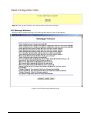
3.8.2 Definition on IGMP v1.0 and v2.0
For IGMP v1.0,
Host Group Addresses
Host groups are identified by class D IP
addresses, i.e., those with "1110" as their
high-order four bits. Class D IP addresses,
i.e., those with "1111" as their high-order
four bits, are reserved for future addressing
modes.
In Internet standard "dotted decimal" nota-
tion, host group addresses range from
224.0.0.0 to 239.255.255.255. The address
224.0.0.0 is guaranteed not to be assigned
to any group, and 224.0.0.1 is assigned to
the permanent group of all IP hosts (in-
cluding gateways). This is used to address
all multicast hosts on the directly connected
network. There is no multicast address (or
any other IP address) for all hosts on the
total Internet. The addresses of other
well-known, permanent groups are to be
published in "Assigned Numbers".
Page is loading ...
Page is loading ...
Page is loading ...
Page is loading ...
Page is loading ...
Page is loading ...
Page is loading ...
Page is loading ...
Page is loading ...
Page is loading ...
Page is loading ...
Page is loading ...
Page is loading ...
Page is loading ...
Page is loading ...
Page is loading ...
Page is loading ...
Page is loading ...
Page is loading ...
Page is loading ...
Page is loading ...
Page is loading ...
Page is loading ...
Page is loading ...
Page is loading ...
Page is loading ...
Page is loading ...
Page is loading ...
Page is loading ...
Page is loading ...
Page is loading ...
Page is loading ...
Page is loading ...
Page is loading ...
Page is loading ...
Page is loading ...
Page is loading ...
Page is loading ...
Page is loading ...
Page is loading ...
Page is loading ...
Page is loading ...
Page is loading ...
Page is loading ...
Page is loading ...
Page is loading ...
Page is loading ...
Page is loading ...
Page is loading ...
Page is loading ...
Page is loading ...
Page is loading ...
Page is loading ...
Page is loading ...
Page is loading ...
Page is loading ...
Page is loading ...
Page is loading ...
Page is loading ...
Page is loading ...
-
 1
1
-
 2
2
-
 3
3
-
 4
4
-
 5
5
-
 6
6
-
 7
7
-
 8
8
-
 9
9
-
 10
10
-
 11
11
-
 12
12
-
 13
13
-
 14
14
-
 15
15
-
 16
16
-
 17
17
-
 18
18
-
 19
19
-
 20
20
-
 21
21
-
 22
22
-
 23
23
-
 24
24
-
 25
25
-
 26
26
-
 27
27
-
 28
28
-
 29
29
-
 30
30
-
 31
31
-
 32
32
-
 33
33
-
 34
34
-
 35
35
-
 36
36
-
 37
37
-
 38
38
-
 39
39
-
 40
40
-
 41
41
-
 42
42
-
 43
43
-
 44
44
-
 45
45
-
 46
46
-
 47
47
-
 48
48
-
 49
49
-
 50
50
-
 51
51
-
 52
52
-
 53
53
-
 54
54
-
 55
55
-
 56
56
-
 57
57
-
 58
58
-
 59
59
-
 60
60
-
 61
61
-
 62
62
-
 63
63
-
 64
64
-
 65
65
-
 66
66
-
 67
67
-
 68
68
-
 69
69
-
 70
70
-
 71
71
-
 72
72
-
 73
73
-
 74
74
-
 75
75
-
 76
76
-
 77
77
-
 78
78
-
 79
79
-
 80
80


Planet SGSW-4802 User manual
- Category
- Network switches
- Type
- User manual
Ask a question and I''ll find the answer in the document
Finding information in a document is now easier with AI
Related papers
-
Planet SGSW-2402 User manual
-
-
-
-
Planet SW-504 User manual
-
Planet MGSW-2402 User manual
-
Planet WGSD-1020 User manual
-
ACTi GS-4210-24P4C / GS-4210-24PL4C Installation guide
-
-
Planet WSD-800 User manual
Other documents
-
Xerox KS-801 User manual
-
Trendnet TE100-S24V Owner's manual
-
Trendnet TE100-S24V Owner's manual
-
MiLAN MIL-S3570 Installation guide
-
 Planet Technology WGSW-24040R User manual
-
KTI Networks KS-801 User manual
-
-
 Alloy Computer Products NS-24T01FS User manual
-
 Planet Technology GSD-1020 User manual
-
 Alloy Computer Products NS-16T01FS User manual


