Page is loading ...

XM2-300HP CableUPS
XM2-300HP, XM2-300HP-CE
Technical Manual
Effective: October 2017

WARNING! ELECTRICAL HAZARD
WARNING! FUMES HAZARD
WARNING! FIRE HAZARD
WARNING! FIRE & ELECTRICAL HAZARD
ATTENTION:
ATTENTION provides specic regulatory/code requirements that may affect the placement of equipment and/or
installation procedures.
There may be multiple warnings associated with the call out. Example:
Safety Notes
This manual contains important safety information that must be followed during the installation and maintenance of the
equipment and batteries. If there are any questions regarding the safe installation or operation of the system, contact
Alpha Technologies or the nearest Alpha representative. Save this document for future reference.
To reduce the risk of injury or death and to ensure the continued safe operation of this product, the following warnings
and notications symbols have been placed throughout this manual. Where these symbols appear, use extra care and
attention.
ELECTRICAL HAZARD WARNING provides electrical safety information to PREVENT INJURY
OR DEATH to the technician or user.
FUMES HAZARD WARNING provides fumes safety information to PREVENT INJURY OR
DEATH to the technician or user.
This WARNING provides safety information for both Electrical AND Fire Hazards
FIRE HAZARD WARNING provides ammability safety information to PREVENT INJURY OR
DEATH to the technician or user.
CAUTION!
CAUTION provides safety information intended to PREVENT DAMAGE to material or
equipment.
NOTICE:
NOTICE provides additional information to help complete a specic task or procedure.

Supporting Documentation
Refer to the following documents for comprehensive installation instructions and safety information.
Available via www.alpha.com.
APP9015S, APP9022S Service Power Supply: Installation and Operation Manual (Alpha p/n 016-537-B0).
DPM Communications Module: AlphaNet DSM Series 3 Technical Manual (Alpha p/n 745-814-B8).
DM3 Communications Module: DM3.0 Series DOCSIS
®
Status Monitor Technical Manual (Alpha p/n 704-939-B0).
Disclaimer
Images contained in this manual are for illustrative purposes only. These images may not match every installation.
Operator is cautioned to review the drawings and illustrations contained in this manual before proceeding. If there are
questions regarding the safe operation of this powering system, please contact Alpha Technologies or the nearest Alpha
representative.
Alpha shall not be held liable for any damage or injury involving its enclosures, power supplies, generators, batteries or
other hardware if used or operated in any manner or subject to any condition not consistent with its intended purpose or is
installed or operated in an unapproved manner or improperly maintained.
Contact Information
Sales information and customer service in USA
(7AM to 5PM, Pacic Time): 1 800 322 5742
Complete technical support in USA
(7AM to 5PM, Pacic Time or 24/7 emergency support): 1 800 863 3364
Sales information and technical support in Canada: 1 800 667 8743
Website: www.alpha.com
Notice of FCC Compliance
Per FCC 47 CFR 15.21:
Changes or modications not expressly approved by the party responsible for compliance could void the user’s authority to
operate the equipment.
Per FCC 47 CFR 15.105:
This equipment when installed in an Alpha enclosure has been tested and found to comply with the limits for a Class B digital
device, pursuant to part 15 of the FCC Rules. These limits are designed to provide reasonable protection against harmful
interference in a residential installation. This equipment generates, uses and can radiate radio frequency energy and, if not
installed and used in accordance with the instructions, may cause harmful interference to radio communications. However, there
is no guarantee that interference will not occur in a particular installation. If this equipment does cause harmful interference
to radio or television reception, which can be determined by turning the equipment off and on, the user is encouraged to try
to correct the interference by one or more of the following measures:
• Reorient or relocate the receiving antenna.
• Increase the separation between the equipment and the receiver.
• Connect the equipment into an outlet on a circuit different from that to which the receiver is connected.
• Consult the dealer or an experienced radio/TV technician for help.
For further information visit: https://www.fcc.gov/guides/interference-dening-source
Changes and Modications not expressly approved by the manufacturer or registrant of this equipment can void your
authority to operate this equipment under Federal Communications Commission rules.
XM2-300HP CableUPS
XM2-300HP, XM2-300HP-CE
Technical Manual
Effective: October 2017
©
2017 by Alpha Technologies, Inc.
3
017-877-B1-001, Rev. C (10/2017)

Table of Contents
XM2-300HP Power Supply Safety Notes ......................................................................................................... 7
Safety Precautions ........................................................................................................................................... 7
Grounding and Earth Connection Notes........................................................................................................... 9
Utility Power Connection Notes ........................................................................................................................ 10
1.0 Introduction ............................................................................................................................................ 12
1.1 Theory of Operation ................................................................................................................................. 13
AC (Line) Operation ................................................................................................................................. 13
Standby Operation ................................................................................................................................... 13
Charger Operation ................................................................................................................................... 15
1.2 XM2-300HP Layout ................................................................................................................................. 16
Transformer Module Overview ................................................................................................................ 16
Inverter Module Overview ........................................................................................................................ 17
Optional Status Monitoring Module ......................................................................................................... 18
1.3 Recommended Enclosure System Options ............................................................................................. 19
Local and Remote Indicator (LRI) ............................................................................................................ 19
AC Indicator (ACI) ................................................................................................................................... 19
AC Surge Protector / Lightning Arrester .................................................................................................. 19
Coaxial surge protector ........................................................................................................................... 19
APP90S /APP9022S (Service Power Supply) ......................................................................................... 19
2.0 Pre-Commissioning ............................................................................................................................... 20
2.1 Initial Inspection ....................................................................................................................................... 20
2.2 Pre-Commissioning Checklist .................................................................................................................. 21
2.3 About the Smart Display .......................................................................................................................... 22
2.4 Using the Smart Display .......................................................................................................................... 23
2.5 Smart Display Glossary ........................................................................................................................... 24
3.0 Commissioning ...................................................................................................................................... 26
3.1 Turn-up and Test ...................................................................................................................................... 26
AC Line Operation ................................................................................................................................... 26
Self Test Operation .................................................................................................................................. 27
Standby Operation .................................................................................................................................. 27
4
017-877-B1-001, Rev. C (10/2017)

4.0 Operation ................................................................................................................................................ 28
4.1 Smart Display modes for XM2-300HP ..................................................................................................... 28
Operation Normal .................................................................................................................................... 28
Comms Information Display (with DPM or DM3) ..................................................................................... 29
Setup Menu ............................................................................................................................................. 30
Menu Structure and Navigation (from Operation Normal screen) ................................................................. 33
Menu Structure and Navigation (from Active Alarms screen) .................................................................. 34
4.2 Alarm Indications ..................................................................................................................................... 35
4.3 Control Panel LEDs ................................................................................................................................. 37
4.4 Automatic Performance Test .................................................................................................................... 38
4.5 Providing Power via Portable Generator or Inverter ................................................................................ 39
AC Powering ............................................................................................................................................ 39
Using a Truck-mounted Inverter or Generator ......................................................................................... 40
4.6 Resumption of Utility Power .................................................................................................................... 40
5.0 XM2-300HP Maintenance ...................................................................................................................... 41
5.1 System Information .................................................................................................................................. 41
5.2 Battery Charger Voltage .......................................................................................................................... 42
5.3 Battery Terminals and Connecting Wires ................................................................................................. 42
5.4 Output Voltage ......................................................................................................................................... 42
5.5 Output Current ......................................................................................................................................... 42
5.6 Check Output Connections ...................................................................................................................... 43
Visual Inspection ...................................................................................................................................... 43
5.7 Inverter Module Maintenance .................................................................................................................. 43
5.8 Maintenance Log ..................................................................................................................................... 44
6.0 Return and Repair Information ............................................................................................................. 45
7.0 Specications ........................................................................................................................................ 46
7.1 Safety and EMC Compliance .................................................................................................................. 47
8.0 Emergency Shutdown ........................................................................................................................... 48
9.0 Appendix ............................................................................................................................................... 49
9.1 Inverter Module Removal and Reinstallation ........................................................................................... 49
9.2 AC Output Voltage Reconguration ......................................................................................................... 50
9.3 Protective Interface Module ..................................................................................................................... 51
9.4 Programming the PIM .............................................................................................................................. 52
9.5 Grounding Wire Connection .................................................................................................................... 53
9.6 Verication of DM3 Jumper Setting ......................................................................................................... 53
Table of Contents, continued
5
017-877-B1-001, Rev. C (10/2017)

Figures
Fig. 1-1, XM2-300HP ......................................................................................................................................... 12
Fig. 1-2, Simplied Block Diagram .................................................................................................................... 14
Fig. 1-3, Charger Modes.................................................................................................................................... 15
Fig. 1-4, Transformer Module Connections ....................................................................................................... 16
Fig. 1-5, AC Input Connections and Product Label ........................................................................................... 16
Fig. 1-6, Smart Display ...................................................................................................................................... 17
Fig. 1-7, Inverter Module Connections .............................................................................................................. 17
Fig. 1-8, Temperature Probe Locations ............................................................................................................. 17
Fig. 1-9, DPM (L) and DM3 (R) ......................................................................................................................... 18
Fig. 2-1, Smart Display Navigation .................................................................................................................... 22
Fig. 2-2, Smart Display Panel ............................................................................................................................ 23
Fig. 3-1, Sample Conguration Screen ............................................................................................................. 26
Fig. 4-1, Operation Normal Display ................................................................................................................... 28
Fig. 4-2, Comms Info Display ............................................................................................................................ 29
Fig. 4-3, Setup Menu Display ............................................................................................................................ 32
Fig. 4-4, Smart Display LEDs ............................................................................................................................ 37
Fig. 8-1 Emergency Shutdown .......................................................................................................................... 48
Fig. 9-1, Removing the Inverter Module ............................................................................................................ 50
Fig. 9-2, Inside of XM2-300HP .......................................................................................................................... 50
Fig. 9-3, Output Voltage Terminal Block Detail .................................................................................................. 50
Fig. 9-4, Power Supply Ground Wire Connection.............................................................................................. 53
Fig. 9-5, Location of Reset Timing Jumper, DM3 .............................................................................................. 53
Tables
Table 3-1, AC Output ......................................................................................................................................... 26
Table 4-1, Major Alarms ..................................................................................................................................... 36
Table 4-2, Minor Alarms ..................................................................................................................................... 36
Table 7-1, XM2-300HP Power Supply Specications ........................................................................................ 46
6
017-877-B1-001, Rev. C (10/2017)

• The XM2-300HP Power Supply contains more than one live circuit! Even though AC voltage is not present at
the input, voltage may still be present at the output.
• The battery string, which provides backup power, contains dangerous voltages. Only qualied personnel
should inspect or replace batteries.
• In the event of a short-circuit, batteries present a risk of electrical shock and burns from high current. Observe
proper safety precautions.
WARNING! ELECTRICAL HAZARD
• Do not allow live battery wires to contact the enclosure chassis. Shorting battery wires can result in a re
or possible explosion.
• If replacing the internal auto style fuses, use only the same type and rating of fuse.
WARNING! ELECTRICAL & FIRE HAZARD
This power supply has been approved by regulatory authorities which require its use with Alpha enclosures. Visit www.
alpha.com to download copies ot the LPE Enclosure Installation and Operation Manual (Alpha p/n 031-302-B0) or the
XM2-300HP Wall-Mount Rack Installation instructions (Alpha p/n 746-221-C0).
ATTENTION:
• Any gelled or liquid emissions from a valve-regulated lead-acid (VRLA) battery contains diluted sulfuric acid,
which is harmful to the skin and eyes. Emissions are electrolytic and are electrically conductive and corrosive.
• If any battery emission contacts the skin, wash immediately and thoroughly with water. Follow your company’s
approved chemical exposure procedures.
• Neutralize any spilled battery emission with the special solution contained in an approved spill kit or with a
solution of one pound bicarbonate of soda to one gallon of water. Report a chemical spill using your company’s
spill reporting structure and seek medical attention if necessary.
• A battery showing signs of cracking, leaking, or swelling should be replaced immediately by authorized
personnel using a battery of identical type and rating.
WARNING! GENERAL HAZARD
• Only qualied personnel may service the XM2-300HP CableUPS
®
.
• Verify the voltage requirements of the equipment to be protected (load), the AC input voltage to the power supply
(line), and the output voltage of the system prior to installation.
• Equip the utility service panel with a properly rated circuit breaker for use with this power supply.
• When connecting the load, DO NOT exceed the output rating of the power supply.
• Always use proper lifting techniques whenever handling units, modules or batteries.
CAUTION!
XM2-300HP Power Supply Safety Notes
Safety Precautions
• Always wear eye protection, rubber gloves and a protective vest when working near batteries. To avoid
electrical shock, remove all metallic objects (such as rings or watches) from your person.
• Use tools with insulated handles. Do not rest any tools on top of batteries.
• Prior to handling the batteries, touch a grounded metal object to dissipate any static charge that may have
developed on your body.
• Use special caution when connecting or adjusting battery cabling. An improperly or unconnected battery cable
can make contact with an unintended surface that can result in arcing, re, or a possible explosion.
WARNING! ELECTRICAL HAZARD
7
017-877-B1-001, Rev. C (10/2017)

Batteries produce explosive gases. Keep all open ames and sparks away from batteries.
WARNING! FIRE HAZARD
• During maintenance visits, inspect batteries for the following:
• Signs of battery cable damage: Battery cable should be replaced immediately by authorized personnel using
replacement parts specied by vendor.
• Loose battery connection hardware: Refer to documentation for the correct torque and connection hardware for
the application.
• Always replace batteries with those of an identical type and rating. Match conductance, voltage and date codes.
Never install untested batteries.
• Do not attempt to remove the vents (valves) from the AlphaCell broadband battery or add water. This is a safety
hazard and voids the warranty.
• Apply electrical contact grease on all exposed connections.
• Follow approved storage instructions.
• Each individual battery should have at least 13mm (1/2”) of space between it and all surrounding surfaces to
allow for convection cooling.
• All battery compartments must have adequate ventilation to prevent an accumulation of potentially dangerous
gas. Never place batteries in a sealed enclosure. Extreme caution should be used when maintaining and
collecting data on the battery system. Ensure all enclosure vents and lters are clean and free of debris.
• Always refer to the battery manufacturer’s recommendation for selecting correct “FLOAT” and “ACCEPT”
charge voltages. Failure to do so can damage the batteries.
• Verify the Power Supply’s battery charger “FLOAT” and “ACCEPT” charger voltage settings.
• Batteries are temperature sensitive. During extremely cold conditions, a battery’s charge acceptance is reduced
and requires a higher charge voltage; during extremely hot conditions, a battery’s charge acceptance is
increased and requires a lower charge voltage. To compensate for changes in temperature, the battery charger
used in the power supply is temperature compensating.
• If the batteries appear to be overcharged or undercharged, rst check for defective batteries and then verify the
correct charger voltage settings.
• To ensure optimum performance, inspect batteries every three to six months for signs of cracking, leaking or
unusual swelling (note that some swelling is normal).
• Check battery terminals and connecting wires. Clean battery terminal connectors periodically and retighten to
approximately 110 inch-pounds (or to manufacturer’s specications if not AlphaCell). Spray the terminals with
an approved battery terminal coating such as NCP-2.
• Check battery voltages UNDER LOAD. Use a load tester if available.
• Refer to the battery manufacturer’s recommendation for correct charger voltages and the power supply
operation manual for corresponding charger settings.
• Establish and maintain a battery maintenance log.
CAUTION!
• Clean up any spilled electrolyte in accordance with all federal, state, and local regulations or codes.
• Spent or damaged batteries are environmentally unsafe. Always recycle used batteries. Refer to local codes for
proper disposal of batteries.
ATTENTION:
Safety Precautions
8
017-877-B1-001, Rev. C (10/2017)

Grounding and Earth Connection Notes
Low impedance grounding is mandatory for personnel safety and critical for the proper
operation of the cable system.
WARNING! ELECTRICAL HAZARD
In order to provide a ready, reliable source of backup power it is necessary to connect the power supply to an effective grounding
and Earthing system that not only provides for the safety of the service personnel responsible for its operation and maintenance,
but also facilitates the proper operation and protection of the equipment within the network. Such a grounding system provides
protection with respect to operator safety, system communication and equipment protection.
Lightning strikes, grid switching or other aberrations on the power line and/or communications cable have the potential to cause
high-energy transients that can damage the powering or communications systems. The most viable method available to protect the
system from damage is to divert these unwanted high-energy transients along a low-impedance path to Earth. A low-impedance
path to Earth prevents these currents from reaching high voltage levels and posing a threat to equipment.
The key to the success of lightning protection is single-point grounding so the components of the grounding system appear as a
single point of uniform impedance. Two places recommended by Alpha for single-point grounding are connections in the enclosure
and connections to Earth. Single-point grounding in the enclosure is achieved by bonding all electrical connections to the enclosure,
including the connection to Earth, as close together on the enclosure as possible. Single-point grounding for the connection to Earth
is achieved, for example, by the proper bonding of the ground rods.
Safety Ground and Earth Connection
The safety ground and Earth is a two-part system, comprised of the utility service and the Alpha system.
1. The utility service:
As a minimum requirement for the protection of Alpha equipment, the local utility service must provide a low-impedance path
for fault current return. In addition, there must be a low impedance bonded path between the Alpha Power Supply power plug
Ground Pin and the Enclosure.
2. The Alpha grounding system:
The Alpha grounding system consists of a low-impedance connection between the enclosure and an Earth Ground (located
at least 6’ away from the Utility Earth connection).
This impedance between the enclosure and Earth must be 25 Ohms or less at 60 Hertz as measured by AMPROBE Model
DGC-1000 or equivalent. The measurement should be made on the wire or ground rod after it exits the enclosure.
Local soil conditions will determine the complexity of the grounding system required to meet the 25 Ohm (maximum)
resistance specied above. For example, a single 8’ ground rod may be sufcient to meet the requirement. In some cases,
a more elaborate system may be required such as multiple ground rods connected by a #6AWG solid copper cable buried
8-12” below the surface. Where this is not possible, contact a local grounding system expert for alternate methods that will
meet the 25 Ohm (maximum) specication.
All ground rod connections must be made by means of a listed grounding clamp suitable for direct burial or
exothermic welding.
Power Output Return
For proper operation, the Service Power Inserter (SPI) must be securely bonded to the enclosure.
Communications Grounding
For an external status monitoring transponder, the transponder chassis is typically bonded via a separate ground wire to the
enclosure. For systems using an embedded transponder, the grounding connection is typically made either through a separate
chassis ground block bonded to the enclosure, or by means of the internal mounting hardware which bonds the transponder through
the XM2-300HP. Please refer to the appropriate Communications product manual for installation procedures.
Alpha strongly recommends on communication cables the use of a surge arresting device electrically bonded to the Alpha
Enclosure.
9
017-877-B1-001, Rev. C (10/2017)

Utility Power Connection Notes
UL and NEC require that a service disconnect switch (UL listed) be provided by the installer and be connected between
the power source and the ALPHA power supply. Connection to the power supply must include an appropriate service
entrance weather head.
Connecting to the utility should be performed only by qualied service personnel and in compliance with local electrical
codes. Connection to utility power must be approved by the local utility before installing the power supply.
ATTENTION:
In order to accommodate the high-inrush currents normally associated with the start-up of active load transformers
(400 Amp, no-trip, rst-half cycle), either a “high-magnetic” or an HACR (Heating, Air Conditioning, Refrigeration)
trip breaker must be used. Either a 15A (minimum required) or 20A rated circuit breaker is acceptable. Do not
replace these breakers with a conventional service entrance breaker. Alpha recommends ONLY Square D breakers
because of the increased reliability required in this powering application. High-magnetic Square D circuit breakers
and a BBX option (UL Listed service entrance) are available from Alpha Technologies.
NOTICE:
Description Alpha Part Number Square D Part Number
120V Installation - High-magnetic (20A)
470-017-10 QO120HM
120V Installation - High-magnetic (15A)
470-013-10 QO115HM
BBX - External Service Disconnect
020-085-10 QO2 -4L70RB
BBX - External Service Disconnect
020-141-10 QO8-16L100RB
In most cases, the following congurations qualify for service entrance use when wiring a duplex receptacle to a service
disconnect. Other codes may also apply. Always contact your local utility to verify that the wiring conforms to applicable
codes.
ATTENTION:
XM2-300HP Connections
Proper 120Vac 15A or 20A service requires the installation site be equipped with a 120Vac duplex receptacle which
provides power to the power supply and peripheral equipment.
Verify the following:
• For 20A service: Have a NEMA 5-20R receptacle that is protected by a single-pole, 20 Amp High Magnetic (HM)
circuit breaker inside the service entrance.
• For 15A service: Have a NEMA 5-15R receptacle that is protected by a single-pole, 15 Amp High Magnetic (HM)
circuit breaker inside the service entrance.
• That, in accordance with NEC CODE, the proper wire AWG (suggested wire gauge is 12AWG) is used.
• The system is equipped with a grounding clamp on the enclosure to facilitate dedicated grounding.
• The system is equipped with a plug-in or hardwired AC Surge Protector/Lightning Arrester for any outdoor
installations. Plug-in Model: LA-P+ 120V or LA-P-120T. Hardwired Model: ISA 120/240 Surge Arrester Kit.
10
017-877-B1-001, Rev. C (10/2017)

Typical 120Vac Service Entrance Wiring
To Utility
Neutral (White)
Neutral Bus
To Enclosure Receptacle
LI Black
LI Black
Grounding Point Made
to Enclosure Wall
Copper Ground
Wire #8 AWG
(Minimum)
Breaker
(P/N 531-006-19)
Neutral
(White)
LI
(Black)
Ground
(Green)
Utility Connection Notes, continued
Typical 120Vac 20A Receptacle Wiring, 5-20R
When bonding the box to a neutral plate is required, use the long green bonding screw provided
(Alpha p/n 523-011-10, Square D p/n 40283-371-50).
NOTICE:
(P/N 531-003-10)
Neutral
(White)
LI
(Black)
Ground
(Green)
Typical 120Vac 15A Receptacle Wiring, 5-15R
11
017-877-B1-001, Rev. C (10/2017)

1.0 Introduction
The modular XM2-300HP is comprised of the:
Inverter module, which is required for standby operations and contains circuitry needed for the three-stage
temperature-compensated battery charger, DC to AC converter (inverter), AC line detectors and Smart Display.
Optional DOCSIS
®
communications module (DPM or DM3), used to provide external status monitoring and
communications.
Chassis, which contains a transformer and transfer isolation relay.
2
1
3
Fig. 1-1, XM2-300HP
Standard features of the XM2-300HP include:
• Smart Display
• Built-in Self Test (with inverter diagnostics)
• Battery test (advanced battery diagnostics)
• A high-efciency transformer
• Improved Status menus
• Communications menu with DOCSIS
®
parameters
Via the Smart Display, the operator can view all of the power supply’s operating parameters. Automatic scrolling (AUTO-
SCROLL) is always active — eliminating the need to press any buttons to view the power supply’s status or system
parameters. In addition to operating parameters, active alarms are automatically displayed on the Smart Display, so that
the operator can immediately see what fault is being detected. Troubleshooting tips automatically display on the Alarm
menu screen.
3
2
1
12
017-877-B1-001, Rev. C (10/2017)

1.0 Introduction, continued
1.1 Theory of Operation
The XM2-300HP powers signal processing equipment in cable television and broadband LAN distribution systems. The
XM2-300HP provides a critical load with current-limited, regulated AC power that is free of spikes, surges, sags and noise.
During AC line operation, AC power entering the power supply is regulated by a multi-tap transformer at the required
output voltage. The regulated voltage is connected to the load via the output connectors, and some power is directed to
the battery charger to maintain a oat charge on the batteries.
When the incoming AC line voltage signicantly deviates from normal, the XM2-300HP inverter module automatically
switches to standby operation and maintains power to the load. In standby mode, the XM2-300HP powers the load until
the battery voltage reaches a low-battery cutoff point.
When utility power returns, the XM2-300HP transformer module waits for a short time (approximately 20 to 40 seconds)
for the utility voltage and frequency to stabilize and then initiates a smooth, in-phase transfer back to AC line power. Once
the transfer is complete, the battery charger recharges the batteries in preparation for the next event.
AC (Line) Operation
During AC Line operation, utility power is routed into the primary winding of the transformer through the contacts of the
line isolation relay and voltage selection relays. Simultaneously, in the inverter, power is directed to the rectier circuitry
providing power for the control circuitry. The bidirectional inverter also serves as a battery charger during line operation.
The transformer and automatic tap relays provide output voltage regulation.
The duration of battery-backed standby operation depends upon the type and number of batteries and the load on
the power supply.
NOTICE:
Standby Operation
When the incoming AC line voltage drops or rises signicantly, or a complete power outage occurs, the control logic’s line
monitor activates standby operation. During the transfer from AC line to standby operation, the battery powered inverter
comes online as the isolation relay switches to prevent AC power from back-feeding to the utility. The following changes
also occur within the XM2-300HP:
• The isolation relay opens to disconnect the AC line from the primary winding of the transformer.
• The control logic drives the inverter FETs on and off at line frequency. This switching action converts DC from the
battery to AC in the transformer winding to provide a regulated power for the load.
• The control logic, which includes a microprocessor and other circuits to protect the inverter FETs from overcurrent
damage, monitors the condition of the battery and the inverter during standby operation. Since a prolonged AC line
outage would severely discharge the battery, resulting in permanent damage, the control logic disables the inverter
when the battery cell voltage drops to 1.75Vdc per cell (10.5Vdc per individual battery).
When acceptable AC line voltage returns, the power supply returns to AC line operation after a 20 to 40 second lag. This
delay allows the AC line voltage and frequency to stabilize before the control logic phase-locks the inverter’s output to the
utility input. The control logic then de-energizes the isolation relay, reconnects the AC line to the primary of the transformer
and disables (turns off) the inverter. This results in a smooth, in-phase transfer back to utility power without interruption
of service to the load. The battery charging circuit then activates to recharge the battery in preparation for the next power
outage.
13017-877-B1-001, Rev. C (10/2017)

1.0 Introduction, continued
Fig. 1-2, Simplied Block Diagram
OUTPUT 1
OUTPUT 2
LRI
TRANSFORMER
INVERTER
BATTERY
INVERTER MODULE ASSEMBLY
POWER DISTRIBUTION BOARD
COAXIAL NETWORK
STATUS MONITORING
CONNECTION
OPTIONAL
COMMUNICATIONS
CARD AND
TRANSPONDER
OUTPUT
VOLTAGE TAP
SELECTOR
SERVICE
POWER INSERTER
(ALPHA SPI)
OPTIONAL SURGE PROTECTOR
REPLACEABLE PRIMARY POWER SUPPLY
OVERVOLTAGE PROTECTION
AC LINE DETECTION
AND CONTROL LOGIC
CIRCUITS
DUAL REMOTE
TEMPERATURE
SENSOR
SURGE PROTECTION
LRI CONTROL CIRCUIT
OUTPUT
CIRCUIT
BREAKER
14 017-877-B1-001, Rev. C (10/2017)

1.0 Introduction, continued
Charger Operation
The XM2-300HP uses a three-stage, temperature-compensated battery charger. During AC line operation, the inverter
winding on the transformer feeds the charger circuit which provides BULK, ACCEPT and FLOAT charge voltages to the
battery.
Charger Modes
BULK
This is a “Constant Current” charge with a maximum current of 10A. As the charge is returned to the batteries, their
voltage increases to a specic threshold (2.27Vdc per cell). The charger then switches to ACCEPT mode. The BULK
charger mode generally returns the battery charge state to 80 percent of rated battery capacity.
ACCEPT
This charge is a “Constant Voltage” charge. The voltage, 2.40Vdc (adjustable) per cell, is temperature-compensated to
ensure longer battery life and proper completion of the charge cycle. This cycle is complete when the charging current into
the battery becomes less than 0.5A, or approximately six hours elapses from the time ACCEPT mode was entered. When
the batteries are fully recharged the charger switches to the FLOAT mode of operation.
FLOAT
This mode is a temperature-compensated “pulsed voltage” charge, averaging about 2.27Vdc (adjustable) per cell. During
FLOAT mode, the battery is fully charged and ready to provide backup power. The charger provides a small maintenance
charge to overcome the battery self-discharge characteristics and other minor DC loads within the power supply. As the
battery voltage reaches the “full charge” level the time delay between pulses increases.
During ACCEPT and FLOAT modes, the cell voltage is temperature-compensated at -0.005Vdc per cell per degree C
(adjustable) to ensure a safe battery cell voltage and to maximize battery life.
Fig. 1-3, Charger Modes
NOTICE:
When AlphaCell is the selected battery type, ACCEPT and FLOAT are pre-set and are not manually selectable.
BATTERY VOLTAGE
BATTERY CURRENT
321
BULK Constant Current Mode (10A max) until battery voltage
reaches the ACCEPT level (2.40V/cell)
ACCEPT Constant Voltage Mode (2.40V/cell) until battery
current demand drops below .5A or time out based on 4 minutes
per Ah battery capacity
FLOAT Constant Voltage Mode (2.27V/cell) Chassis, which
contains a transformer and transfer isolation relay.
2
1
3
15017-877-B1-001, Rev. C (10/2017)

1.0 Introduction, continued
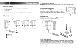
Fig. 1-4, AC Input Connections and Product Label
3
2
1
Line Cord / Circuit Breaker Protective Tab
4
Output 1
2
8A Circuit breaker
5
Output 2
3
Product Label
6
Local/Remote Indicator (LRI) Connector
5
4
6
1.2 XM2-300HP Layout
Transformer Module Overview
AC Output Circuit Protection:
XM2-300HP power supplies use an 8A circuit breaker. To provide increased durability, an integrated sheet metal guard
protects the line cord and circuit breaker.
Output 1 (White = Neutral, Black = Line):
The AC output connector is clearly marked for easy identication. The service power inserter (SPI) connects directly into
the Output 1 connector.
Output 2 (Optional) [White = Neutral, Black = Line]:
The AC output connector is clearly marked for easy identication. The SPI, which couples power to the load, connects
directly into the Output 2 connector. This feature is part of the factory-installed PIM.
LRI (Local/Remote Indicator):
The LRI lamp option is used in conjunction with the automatic performance feature and plugs directly into the LRI
connector. The LRI circuit is rated at 12Vdc, 250mA, and duplicates the function of the red ALARM LED by illuminating an
externally mounted red lamp for standby operation.
1
16 017-877-B1-001, Rev. C (10/2017)

1.0 Introduction, continued
Inverter Module Overview
The removable inverter module provides uninterrupted power to the transformer (via the batteries) during line failures.
During line operation, the inverter charges the battery using a three-stage (BULK, ACCEPT, and FLOAT) charger. The
Inverter Module houses the following:
Smart Display:
All operational functions, system testing, setup items, and alarms are available
via the Smart Display panel on the front of the XM2-300HP (the Smart Display
is covered in detail in Section 2.3). Display functions are accessible by pressing
any of the four keys: ESCAPE, UP, DOWN or ENTER. Backlighting is activated
when any of the four keys are pressed, and stays lit for a period of one hour. There
are four levels of menu items: Operation Normal, Communication Information,
Setup and Alarms. Pressing ENTER will sequence the display one level lower,
and pressing ESCAPE will sequence the display one level higher. Additionally,
built-in metering circuits measure and indicate voltage and current, without the
need for external test equipment.
Battery Switch:
The battery switch disconnects the battery from the inverter module’s DC circuit. With the battery switch turned off, the
XM2-300HP power supply does not transfer to standby mode, the inverter is disabled, and the battery charger cannot
charge the battery.
Battery Input Connector
The battery cable connector is polarized and plugs directly into the inverter module’s battery connector.
Temp Probe Connector:
The Dual Remote Temperature Sensor (DRTS) plugs directly into the temperature probe (RJ-11C type) connector. One
sensor clips onto the front edge of the power supply shelf and monitors the ambient air temperature within the enclosure.
The second sensor attaches to the negative terminal of the battery and monitors battery temperature. To install, connect
the ring terminal onto the negative battery terminal as shown below.
Fig. 1-6, Inverter Module Connections
Fig. 1-7, Temperature Probe Locations
Always verify proper polarity of cables before connecting the battery to the power module. Polarity is clearly marked
for easy identication. Reversing the polarity prevents the battery from being active in the system.
NOTICE:
Fig. 1-5, Smart Display
FOR COMMS INFO
OUTPUT VOLTAGE 67V
Temp Probe
Connector
Battery
Switch
Battery Input
Connector
17017-877-B1-001, Rev. C (10/2017)

1.0 Introduction, continued
Optional Status Monitoring Module
The XM2-300HP supports the Alpha Technologies DPM (DOCSIS 2.0) or DM3 (DOCSIS 3.0) communication module. The
module may be ordered factory-installed or as a user-installed eld upgrade.
Handle these modules with extreme care. Circuit boards and logic upgrades are static-sensitive and
susceptible to damage.
If communications options are installed, Alpha recommends adding a coaxial surge arrestor for the transponder.
Tighten the RF cable connector and the cables attached to the Grounded Surge Protector to a Torque setting of
10in-lb ± 1in-lb. (See Section 1.3, Optional Features).
DOCSIS
®
Communication Module
Network-enable your power supply and access powerful diagnostic tools using the DPM or DM3 embedded WEB
interface and standard SNMP. Poll power supply and battery data in real-time, and receive alerts when power system
alarms indicate noteworthy events. The DPM or DM3 is completely congurable from the standard cable modem
conguration le and can be provisioned using default cable modem settings. Customize your monitored information with
congurable CM settings that are used to set alarm thresholds and power supply operating parameters.
Visit www.alpha.com to download a copy of the technical manual for the installed communications module. Information
regarding the DPM is found in the AlphaNet DSM Series 3 Technical Manual (Alpha p/n 745-814-B8). Information
regarding the DM3 is found in the DM3.0 Series DOCSIS
®
Status Monitor Technical Manual (Alpha p/n 704-939-B0).
Fig. 1-9, DPM (L) and DM3 (R)
ENV – Environmental Connector
ETH – Ethernet Connector
TPR – Tamper Switch Connector
RF Cable Connector
ENV – Environmental Connector
ETH – Ethernet Connector
TPR – Tamper Switch Connector
RF Cable Connector
NOTICE:
CAUTION!
18 017-877-B1-001, Rev. C (10/2017)

1.0 Introduction, continued
1.3 Recommended Enclosure System Options
These options can be factory installed or upgraded in the eld by the user:
Local and Remote Indicator (LRI)
The LRI (red) lamp is located on the outside of pole-mount enclosures. Using this simple form of status monitoring
operators can check the operational status of the power supply without having to climb the pole and open the enclosure.
During normal AC line operation, the LRI remains off. The LRI comes on only when the power supply is running in standby
mode. Whenever a fault is detected during Self Test, the LRI ashes to indicate that service is required.
AC Indicator (ACI)
The AC Indicator (green lamp) is located next to the LRI on the outside of pole-mount enclosures and also acts as a
simple form of status monitoring so cable technicians can check the output status of the power supply without having to
climb the pole and open the enclosure. As long as there is voltage present at the output, the ACI remains on. To provide
much longer life than the original light bulb design, use the ACI-LL (long life LED). Models for 60V and 90V are available.
Do not use ACIs for ground mount enclosures.
AC Surge Protector / Lightning Arrester
AC surge protectors may be plugged directly into the AC outlet or hardwired into the utility power feed depending on the
model. For outdoor installations of the XM2-300HP, the AC surge protector is required to meet agency compliance.
Coaxial Surge Protector
Alpha recommends using coaxial surge suppression for enclosure protection. The Coax Surge Protector
(Alpha p/n 162-028-10) includes 75 ohm surge protector and mounting hardware.
APP9015S / APP9022S (Service Power Supply)
The APP9015S / APP9022S is a portable, non-standby power supply that provides conditioned AC power to the load
when the main power module is out of service. An internal tap lets the APP9015S / APP9022S be set for 90/75/60Vac
applications. Use a 15A or 25A SPI (Service Power Inserter) to transfer power from the APP9015S / APP9022S to the
load.
19017-877-B1-001, Rev. C (10/2017)

Pre-installation Inspection
1. Remove the XM2-300HP from the shipping container. Conrm that the power supply, including the Remote
Temperature Sensor, and all other ordered options are included.
2. During shipping, components might shift. Carefully inspect the power supply and other contents for possible
shipping-related failures, such as loosened or damaged connectors. If any items are damaged or missing, contact
Alpha Technologies or the shipping company immediately. Most shipping companies have a short claim period.
3. Do not attempt to install a damaged power supply without rst passing a complete pre-installation inspection and
start-up test.
2.0 Pre-Commissioning
2.1 Initial Inspection
Use the original shipping container if the XM2-300HP needs to be returned for service. If the original container is not
available, make sure the unit is well packed with at least three inches of shock-absorbing material to prevent shipping
damage.
See the “CableUPS Quick Start Guide” (Alpha p/n 017-877-B0) that accompanies each power supply. SAVE THE
ORIGINAL SHIPPING CONTAINER.
Output voltage reconguration is only to be performed by authorized personnel.
ATTENTION:
Read the Safety Precautions, Utility Power Connection Notes, and Grounding Connection Notes (pages
8-11) before you install the power supply.
CAUTION!
Do not use popcorn-type material. Alpha Technologies is not responsible for damage caused by
improper packaging of returned units.
CAUTION!
NOTICE:
20
017-877-B1-001, Rev. C (10/2017)
/