Page is loading ...

ASSEMBLING & INSTALLATION INSTRUCTIONS PRODUCT# 8485-57
WARNING!SHUTPOWEROFFATFUSEORCIRCUITBREAKER.
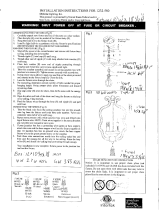
ASSEMBLINGTHEFIXTURE(Fig.2).
1.Returnthefivearmstosuitableposition,seefigure.2.
2.Attachtheloop(A)tothefixturebody(E)byturningit
clockwiseuntiltight.
3.Installa7Wlightbulbandattachtheglassshade(H)tothe
bottomofthelampbody(E)usingthescrews(F).
4.Placetheglassshade(D)andthecollarring(C)ontothe
socketofthefixturebody(E),thenlockitsecurelywiththe
checkring(B).
HANGINGTHEFIXTURE(Fig.1)
1.Shutoffthepoweratthecircuitbreakerandremoveold
fixturefromceiling,includingtheoldcrossbar.
2.Carefullyunpacknewfixtureandlayallthepartsonaclear
surface.
3.Threadnipple(C)intoloop(F)untilsnug.
4.Threadotherendofnipple(C)withloopattachedinto
crossbar(D)untilsnug.
5.Placelockwasher(B)overendofnippleprotrudingthrough
crossbarandthreadhexnut(A)ontonippleuntiltight.
6.Takethiscrossbarassemblyandmounttoceilingjunction
boxwithjunctionboxscrews(E).Tightenscrewssecurely
withscrewdriver.
7.Usingproperchainplierstoopenoneendlinkofthechain
providedandconnecttothefixtureloop(I).Closethelink.
8.Bymeasuring,determinecorrectnumberoflinksneededfor
properhangingheight.Usingproperchainpliersdisconnect
anddiscardremainingchain.
9.Lacethefixturewiresthroughthechain.
10.Sliploopcollar(H)overthechain,thendothesamewiththe
canopy(G).
11.Opentheotherendlinkofthechainandhangthefixtureon
theloopattheceiling.Closethelink.
12.Feedthefixturewiresthroughtheloop(F)andnipple(C)
andpulluntiltaut.
13.Slidecanopy(G)upflushtoceiling,secureusingloop(H).
CONNECTINGTHEWIRES(Fig.3)
1.Taketheblackwirefromtheceilingjunctionboxandthe
smoothwirelegfromthefixtureandtwistbareends
together.Twistwireconnectorontoendofwireuntilsnug.
2.Repeatsameprocesswithwhitejunctionboxwireandribbed
wirelegoffixturewire.NOTE:Twistwirestogetherinthe
samedirectionyoutwistthewireconnectorontowires.
3.Ifyourjunctionboxhasagroundingwire(greenorbare
copper),attachthiswireandthebarecopperwirefromthe
f ixturetogetherasstep1.Ifjunctionboxhasnogroundwire,
attachthebarecopperfixturewiretothegreengroundscrew
onthecrossbar.
4.Tuckthesewireconnectionsneatlyintotheceilingoutletbox
andthenraisethecanopy(G)allthewaytotheceiling.
Raisetheloop(H)andthreadontoceilingloopprotruding
throughcanopy
Yourinstallationisnowcomplete.Returnpowertothe
junctionboxandtestthefixture.
E
Fig.1
Fig.2
Fig.3
White or
HOUSE
Black
WIRES
(Hot)
Smooth
FIXTURE
WIRES
Black or
Ribbed
WIRES
FIXTURE
Bare Copper(Ground)
FIXTURE
WIRES
Copper
(Ground)
HOUSE
(Neutral)
WIRES
White
Bare
Green or
WIRES
HOUSE
/


