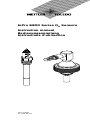
Mettler Toledo O2 Sensors InPro6800 and InPro6800 Gas Operating instructions
- Type
- Operating instructions

InPro 6800 Series O
2
Sensors
Instruction manual
Bedienungsanleitung
Instructions d’utilisation
InPro 6800
52 200 953 B

2 InPro 6800 Series O
2
Sensor 12/25 mm
InPro 6800 © 12/2018 Mettler-Toledo GmbH
52 200 953 B Printed in Switzerland
English Page 3
Deutsch Seite 40
Français Page 76
InDip, InFit, InPro, ISM, and InTrac are registered trademarks
of the METTLER TOLEDO Group in Switzerland and a further
twelve countries.

InPro 6800 Series O
2
Sensor 12/25 mm 3
© 12/2018 Mettler-Toledo GmbH InPro 6800
Printed in Switzerland 52 200 953 B
InPro 6800 Series O
2
Sensors
Instruction manual

4 InPro 6800 Series O
2
Sensor 12/25 mm
InPro 6800 © 12/2018 Mettler-Toledo GmbH
52 200 953 B Printed in Switzerland
1 Introduction................................................................5
2 Important notes ..........................................................6
2.1 Notes on operating instructions .....................................6
2.2 Intended use ...............................................................6
2.3 Safety instructions........................................................7
2.4 Correct disposal of the sensor .......................................9
2.5 Examples of some typical applications...........................9
2.6 Use in Ex-zones.........................................................10
2.7 Ex-classification ATEX ................................................11
2
.7.1 Introduction...............................................................11
2.7.2 Rated data ................................................................11
2.7.3 Special conditions......................................................12
2.8 Ex-classification – FM approved ..................................13
2.8.1 Introduction...............................................................13
2.8.2 Rated data ...............................................................14
2.8.3 Special conditions......................................................14
2.8.4 Applied standards: .....................................................15
3 Product description...................................................16
3.1 General information....................................................16
3.2 Principle ...................................................................16
3.3 Scope of delivery .......................................................16
3.4 Equipment features ....................................................17
4 Installation...............................................................19
4.1 Mounting the sensor...................................................19
4.2 Connection................................................................20
4.2.1 Connecting the InPro 6800 to a cable ..........................20
4.2.2 Connecting the VP or AK9 cable to the transmitter..........20
5 Operation.................................................................21
5.1 Start-up and polarizing ...............................................21
5.2 Calibration ................................................................22
5.2.1 Purpose of calibration ................................................22
5.2.2 What you have to know for calibration .........................22
5.2.3 Single point calibration ...............................................23
5.2.4 Dual point calibration .................................................24
6 Maintenance ............................................................25
6.1 Inspection of the sensor..............................................25
6.1.1 Visual inspection .......................................................25
6.1.2 Testing the sensor with the METTLER TOLEDO
O2Sensor - Master InPro 6800.....................................26
6.1.3 Testing the sensor via a transmitter ..............................27
6.2 Changing the electrolyte,
the membrane body or the interior body .......................28
7 Storage....................................................................31
8 Product specification ................................................31
8.1 Certificates ................................................................31
8.2 Specifications ............................................................32
9 Ordering information.................................................33
9.1 Sensors ....................................................................33
9.2 Accessories...............................................................33
9.3 Spare parts ...............................................................34
9.4 Recommended transmitter ..........................................34
9.5 Recommended housings ............................................34
10 Theory of the polarographic sensor ............................35
10.1 Introduction...............................................................35
10.2 Principle of the design of an oxygen electrode ...............36
10.3 Parameters determining current ...................................36
10.4 Polarization voltage ...................................................37
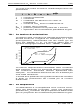
10.5 Temperature ..............................................................37
10.6 Dependence on flow...................................................38
10.7 Oxygen partial pressure – oxygen concentration ............39
Contents

InPro 6800 Series O
2
Sensor 12/25 mm 5
© 12/2018 Mettler-Toledo GmbH InPro 6800
Printed in Switzerland 52 200 953 B
1 Introduction
Thank you for buying the InPro
®
6800 sensor from
METTLER TOLEDO.
The construction of the InPro 6800 sensors employs
l
eading edge tech nology and complies with safety
regulations currently in force. Notwithstanding this,
improper use could lead to hazards for the user or a
third-party, and/or adverse effects on the plant or
o
ther equipment. Therefore, the operating instruc-
tions must be read and understood by the persons
involv ed before work is started with the sensor.
The instruction manual must always be stored close at
hand, in a place accessible to all people working with
the InPro 6800.
If you have questions, which are not or insufficiently
answered in this instruction manual, please contact
your METTLER TOLEDO supplier. They will be glad to
assist you.

6 InPro 6800 Series O
2
Sensor 12/25 mm
InPro 6800 © 12/2018 Mettler-Toledo GmbH
52 200 953 B Printed in Switzerland
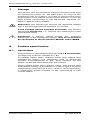
2
Important notes
2.1 Notes on operating instructions
These operating instructions contain all the information
needed for safe and proper use of the oxygen sensor.
T
he operating instructions are intended for personnel
entrusted with the operation and maintenance of the
sensors. It is assumed that these persons are familiar
with the equipment in which the sensor is installed.
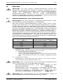
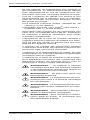
Warning notices and symbols
This instruction manual identifies safety instructions
and additional information by means of the following
symbols:
This symbol draws attention to safety instructions and
warnings of potential danger which, if neglected,
could result in injury to persons and/or damage to
property.
This symbol identifies additional information and
instruc tions which, if neglected, could lead to defects,
inefficient operation and possible loss of production.
2.2 Intended use
METTLER TOLEDO InPro 6800 sensors are intended
solely for inline measurement of the oxygen partial
pressure in liquids and gases, as described in this
instruction manual.
Any use of these sensors which differs from or exceeds
the scope of use described in this instruction manual
will be regarded as inappropriate and incompatible
with the intended purpose.
The manufacturer/supplier accepts no responsibility
whatsoever for any damage resulting from such
improper use. The risk is borne entirely by the user/
operator.
Other prerequisites for appropriate use include:
– compliance with the instructions, notes and
requirements set out in this instruction manual.
– acceptance of responsibility for regular inspection,
maintenance and functional testing of all asso -
ci ated components, also including compliance
with local operational and plant safety regulations.
– compliance with all information and warnings
given in the documentation relating to the products
used in conjunction with the sensor (housings,
transmitters, etc.).
– observance of all safety regulations governing the
equipment in which the sensor is installed.

InPro 6800 Series O
2
Sensor 12/25 mm 7
© 12/2018 Mettler-Toledo GmbH InPro 6800
Printed in Switzerland 52 200 953 B
– correct equipment operation in conformance with
t
he prescribed environmental and operational
conditions, and admissible installation positions.
–
consultation with METTLER TOLEDO Process
Analytics in the event of any uncertainties.
2.3 Safety instructions
– The plant operator must be fully aware of the
potential risks and hazards attached to operation
of the particular process or plant. The operator is
responsible for correct training of the workforce, for
signs and markings indicating sources of possible
danger, and for the selection of appropriate,
state-of-the-art instrumentation.
– It is essential that personnel involved in the
commissioning, operation or maintenance of these
sensors or of any of the associated equipment (e.g.
housings, transmitters, etc.) be properly trained in
the process itself, as well as in the use and
handling of the associated equipment. This
includes having read and understood this instruc-
tion manual.
– The safety of personnel as well as of the plant itself
is ultimately the responsibility of the plant operator.
This applies in particular in the case of plants
operating in hazardous zones.
– The oxygen sensors and associated components
have no effect on the process itself and cannot
influence it in the sense of any form of control
system.
– Maintenance and service intervals and schedules
depend on the application conditions, composition
of the sample media, plant equipment and signi -
ficance of the safety control features of the
measuring system. Processes vary considerably,
so that schedules, where such are specified, can
only be regarded as tentative and must in any case
be individually established and verified by the plant
operator.
– Where specific safeguards such as locks, labels,
or redundant measuring systems are necessary,
these must be provided by the plant operator.
– A defective sensor must neither be installed nor put
into service.
– Only maintenance work described in this operating
instruction may be performed on the sensors.
– When changing faulty components, use only
original spare parts obtainable from your METTLER
TOLEDO supplier (see spare parts list, ”Section
9.3”).

8 InPro 6800 Series O
2
Sensor 12/25 mm
InPro 6800 © 12/2018 Mettler-Toledo GmbH
52 200 953 B Printed in Switzerland
– No modifications to the sensors and the acces-
s
ories are allowed. The manufacturer accepts no
responsibility for damages caused by unauthorised
modifications. The risk is borne entirely by the user.
– When using cables for sensor connection not
supplied and recommended by the manufacturer
the following standards need to be considered:
• US National Electrical Code
®
(ANSI/NFPA 70
[
NEC
®
]
), where applicable.
• Canadian Electrical (CE) Code
®
(CEC Part 1,
C
AN/CSA-C22.1), where applicable.
− For guidance on US installations, see ANSI/
ISA-RP12.06.01, Installation of Intrinsically Safe
Systems for Hazardous (Classified) Locations.
− Control room equipment connected to intrinsically
safe associated apparatus in the US should not
use or generate more than the specified Um of the
associated apparatus.
− Care must be taken during installation to avoid
impacts or friction that could create an ignition
source.
− Tampering and replacement with non-factory
components may adversely affect the safe use of
the system.
− Insertion or withdrawal of removable electrical
connectors or modules is to be accomplished only
when the area is known to be free of flammable
vapors.
− Warning – Intrinsically safe apparatus can
be a sourceof ignition if internal spacings
are shorted or connections opened.
− Warning – Do not open when an explosive
atmosphere is present.
− Warning – Substitution of components may
impair intrinsic safety.
− Warning – Substitution of components may
impair suitability of the equipment.
− Warning – For connection only to non-
flammable processes.
− Warning – To maintain the enclosure IP 66
rating, the connector must be fully engaged.

InPro 6800 Series O
2
Sensor 12/25 mm 9
© 12/2018 Mettler-Toledo GmbH InPro 6800
Printed in Switzerland 52 200 953 B
2.4 Correct disposal of the sensor
When the sensor is finally removed from service, ob-
serve all local environmental regulations for proper
d
isposal.
2.5 Examples of some typical applications
Below is a list of examples of typical fields of applica-
tion for the oxygen sensors. This list is not exhaustive.
Measurement in liquids:
– Fermentation
– Yeast propagation
– Wort aeration
– Spring water conditioning
– Storage ans processing of fruit juices
Measurement in gases:
– Monitoring of the oxygen limit value to protect
products from oxidation.
– Monitoring of the oxygen limit value in the exhaust
air of fermentation vessels.
– Monitoring of oxygen limit values during inertization
processes.
– Measurement of oxygen concentrations in process
gas mixtures.

10 InPro 6800 Series O
2
Sensor 12/25 mm
InPro 6800 © 12/2018 Mettler-Toledo GmbH
52 200 953 B Printed in Switzerland
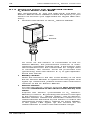
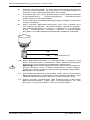
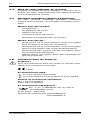
2.6 Use in Ex-zones
Attention!
For an installation in Ex-zones please read the
guidelines following hereafter:
1258
Ex-classification ATEX:
Ex ia IIC T6/T5/T4/T3 Ga/Gb
E
x ia IIIC T69°C/T81°C/T109°C/T161°C Da/Db
Number of the test certificate:
SEV 14 ATEX 0169 X
IECEx SEV 14.0026X
Ex-classification FM approved:
IS/ I, II, III /1/ABCDEFG/ T6 Ta = 60 °C
- 53 800 002; Entity
Project ID: 3021227
FM certificate number: FM16US0034X
FM18CA0021X

InPro 6800 Series O
2
Sensor 12/25 mm 11
© 12/2018 Mettler-Toledo GmbH InPro 6800
Printed in Switzerland 52 200 953 B
2.7 Ex-classification ATEX
2.7.1 Introduction
According to Directive 2014/34/EU (ATEX 95)
Appendix l, lnPro 6XXX*/*/*/*/* oxygen sensors are
devices group ll, category 1/2G and according to
RL 99/92/EG (ATEX 137) may be used in zones
0/1 or 1/2 or 1 or 2 and gas groups llA, llB and llC that
are potentially explosive due to combustible sub-
stances in above stated temperature classes.
For use / installation, the requirements of EN 60079-
14 must be observed.
According to Directive 2014/34/EU (ATEX 95)
Appendix l, lnPro6XXX*/*/*/*/* oxygen sensors are
devices group ll,category 1/2D and according to
RL 99/92/EG (ATEX 137) may also be used in zones
20/21 or 21 or 22 that contain combustible dusts.
The digital sensor circuit is part of a common intrinsi-
cally safe system and is for operation connected to a
separately certified transmitter.
The digital sensor circuit as part of an intrinsically safe
system is isolated from the not-intrinsically safe electric
circuits up to a maximum rated voltage of 375 V and
from grounded parts up to a maximum rated voltage
of 30 V.
2.7.2 Rated data
Measuring circuit:
Fail-safe ignition protection class Ex ia IIC only for
connection to a certified fail-safe circuit.
Analog oxygen sensor maximum values:
U
i
≤ 16 V
I
i
≤ 190 mA
P
i
≤ 200 mW
L
i
= 0 (effective internal inductance)
C
i
= 900 pF (effective internal capacitance)
Note:
The above maximum values are each the total of all in-
dividual circuits of the associated intrinsically safe
power supply and transmitter.

12 InPro 6800 Series O
2
Sensor 12/25 mm
InPro 6800 © 12/2018 Mettler-Toledo GmbH
52 200 953 B Printed in Switzerland
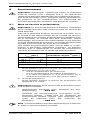
2.7.3 Special conditions
– The relationship between the maximum permissible
ambient or media temperature and temperature
class, for category 1G applications, zone 0, is
shown in the following table:
Temperature class Max. ambient or
media temperature
T 6 68 °C
T 5 80 °C
T 4 108 °C
T 3 160 °C
– The relationship between the maximum permissible
ambient or media temperature and temperature
class, for category 1D applications, zone 20, is
shown in the following table:
Temperature class Max. ambient or
media temperature
T 69 °C 68 °C
T 81 °C 80 °C
T 109 °C 108 °C
T 161 °C 160 °C
– The capacitance and inductance of the connecting
cable has to be considered.
– The oxygen sensor type InPro 6XXX can be
used in / with the fittings InFit
®
76*-*** or
InTrac
®
7**-***, or in / with other suitable fittings in
potentially explosive areas.
– The metal body of the oxygen sensors, or the fittings
InFit 76*-*** or InTrac 7**-***, or other appropriate
fitting is optionally included in the routine pressure
test of the system.
– The independent fitting used for installation of
oxygen sensor must be conductively connected
<to the equipotential bonding system.

InPro 6800 Series O
2
Sensor 12/25 mm 13
© 12/2018 Mettler-Toledo GmbH InPro 6800
Printed in Switzerland 52 200 953 B
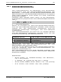
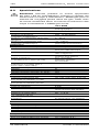
2.8 Ex-classification – FM approved
2.8.1 Introduction
The following FM control drawing and the standards
listed in section 2.8.4 must be observed, where
applicable:
a
a
pappapprapproapprovapproveapprovedapproved
a
a
pappapprapproapprovapproveapprovedapproved

14 InPro 6800 Series O
2
Sensor 12/25 mm
InPro 6800 © 12/2018 Mettler-Toledo GmbH
52 200 953 B Printed in Switzerland
2.8.2 Rated data
F
or rated data please observe section 2.7.2.
2.8.3 Special conditions
I
n type of protection intrinsically safe apparatus, the
a
nalytical probes (InPro 6000 Series with InFit 76X/Y
a
nd InTrac 7XX/YY Series Housings) equipment is
d
esignated with the following specific conditions of
u
se.
1. The dissolved oxygen sensor shall be installed in
c
ompliance with the enclosure, mounting, spacing
and segregation requirements of the ultimate appli-
cation, including a tool removable cover, and is
suitable for use with FM Approved InFit 76X/Y and
InTrac 7XX/YY Series housings.
2. Process temperature no greater than +130 ºC.
3. Maximum permissible working pressure is 12 barg
(174 psig).
4. Potential Electrostatic Charging Hazard – To pre-
vent the risk of electrostatic sparking, the non-
metallic surface should only be cleaned with a
damp cloth.
5. Enclosures containing titanium constitute a poten-
tial risk of ignition by impact or friction. Care must
be taken into account during installation and use
to prevent impact or friction.

InPro 6800 Series O
2
Sensor 12/25 mm 15
© 12/2018 Mettler-Toledo GmbH InPro 6800
Printed in Switzerland 52 200 953 B
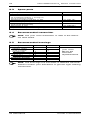
2.8.4 Applied standards:
U
nited States Standards
Canadian Standards
Title Number Issue
Date
Approval Standard for
Electrical Equipment for Use
in Hazardous (Classified)
Locations – General Require-
ments.
FM Class 3600 2011
Approval Standard for
Intrinsically Safe Apparatus
and Associated Apparatus for
Use in Class I, II & III,
Division 1, Hazardous
(
Classified) Locations.
FM Class 3610 2015
Approval Standard for
Electrical Equipment for
Measurement, Control and
Laboratory Use.
FM Class 3810 2005
Explosive Atmospheres –
Part 0: Equipment –
General Requirements.
ANSI/ISA-60079-0
(12.00.01)
2005
Explosive Atmospheres –
Part 11: Equipment
Protection by Intrinsic
Safety ”i”.
ANSI/ISA-60079-11
(12.02.01)
2009
Safety Requirements for
Electrical Equipment for
Measurement, Control,
and Laboratory Use –
Part 1: General Requirements.
ANSI/ISA-61010-1
(82.02.01)
2004
Title Number Issue
Date
Explosive Atmospheres –
Part 0: Equipment –
General Requirements.
CAN/CSA-C22.2
No. 60079-0
2005
Explosive Atmospheres –
Part 11: Equipment
Protection by Intrinsic
Safety ”i”.
CAN/CSA-C22.2
No. 60079-11
2009
Safety Requirements for
Electrical Equipment for
Measurement, Control,
and Laboratory Use –
Part 1: General Requirements.
CAN/CSA-C22.2
No. 61010-1
2004

16 InPro 6800 Series O
2
Sensor 12/25 mm
InPro 6800 © 12/2018 Mettler-Toledo GmbH
52 200 953 B Printed in Switzerland
3
Product description
3.1 General information
The sensor InPro 6800 with integrated temperature
probe is used for oxygen meas ure ment.
T
he sensor is sterilizable and autoclavable and
compatible with CIP (cleaning in place).
InPro 6800 sensors with ISM
®
functionality offer Plug
a
nd Measure as well as enhanced diagnostics
features.
ISM sensors are available with K8S (fully digital) or VP
connector.
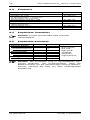
3.2 Principle
Here is a short summary of the principle of pola -
rographic measurement on which this sensor is based
(Clark 1961).
a) The Clark polarographic sensor basically consist
of a working electrode (cathode), a counter/refer-
ence electrode (anode), and an oxygen permeable
mem brane which separates the electrodes from the
sample medium.
b) The transmitter supplies a constant polarization
voltage to the cathode, needed to reduce oxygen.
c) The oxygen molecules which migrate through the
permeable membrane are reduced at the cathode.
At the same time, oxidation takes place at the
anode and oxidized anode metal (silver) is libe -
rated as silver ions into the electrolyte. The electro -
lyte closes the electric circuit between anode and
cathode (ion conductivity).
d) The current produced by the reactions described
above is measured by the transmitter and is
proportional to the partial pressure of oxygen
(pO
2
) in the sample medium.
Please refer to Section 10 ”Theory of the polarogra phic
sensor” for further information.
3.3 Scope of delivery
Each sensor is supplied fully assembled and factory-
tested for correct function together with:
– a quality control certificate
– inspection certificates 3.1B
(complying with EN 10204.3/1B)
See electrolyte order details at section „Spare Parts“,
9.3.

InPro 6800 Series O
2
Sensor 12/25 mm 17
© 12/2018 Mettler-Toledo GmbH InPro 6800
Printed in Switzerland 52 200 953 B
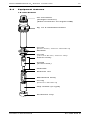
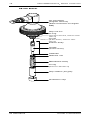
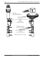
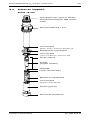
3
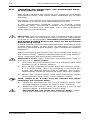
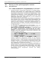
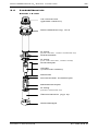
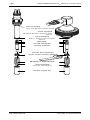
.4 Equipment features
12 mm Sensor
V
P connector
(straight version)
(K8S connector for digital ISM)
O-ring
(10.77x2.62 mm, Silicone FDA)
Interior body
Anode
(solid silver)
Cathode
Retainer nut
O-ring
(Silicone FDA/USP VI)
Cap sleeve (N-type)
Protection cap
Washer
Pg 13.5 threaded sleeve
O-ring
(9.0x1.0 mm, Silicone FDA/USP VI)
Membrane body

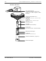
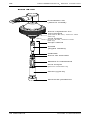
18 InPro 6800 Series O
2
Sensor 12/25 mm
InPro 6800 © 12/2018 Mettler-Toledo GmbH
52 200 953 B Printed in Switzerland
Cap nut G1"
O-ring
(20.29 x2.62 mm, Silicone FDA/
USP VI)
Interior body
Anode
(solid silver)
Cathode
Retainer nut
Membrane body
Cap sleeve (N-type)
Protection cap
25 mm Sensor
O-ring
(9.0x1.0 mm, Silicone FDA/
USP VI)
O-ring
(Silicone FDA/USP VI)
V
P connector
(angled version)
(K8S connector for digital
ISM)

InPro 6800 Series O
2
Sensor 12/25 mm 19
© 12/2018 Mettler-Toledo GmbH InPro 6800
Printed in Switzerland 52 200 953 B
4 Installation
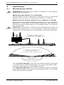
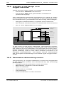
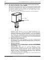
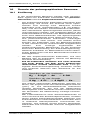
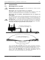
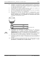
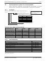
4.1 Mounting the sensor
Important! Remove the green protective cap before
mount ing the sensor.
M
ounting the sensor in a housing
Please refer to the instruction manual of your housing
e
xplaining on how to mount the sensor in place.
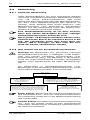
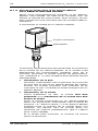
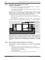
Mounting the sensor directly on a pipe or a vessel
The sensor can be mounted vertically or in an inclined
position. In the case of inclined mounting, the angle of
the housing must be equal to or greater than 15° above
the horizontal.
Caution! Installation outside the admissible range of
mounting positions is not allowed, otherwise correct
operation of the sensors /electrodes may be impaired.
The 12 mm sensors can be mounted directly through
a socket with inside thread Pg 13.5 and securely tight-
ened via the Pg 13.5 threaded sleeve.
The 25 mm sensors can be mounted directly through
a standard weld-in socket or the safety weld-in sockket
from METTLER TOLEDO.
52910536
Admissible mounting positions
Zulässige Einbaulagen
P
ositionements de montage admis
Admissible mounting position
Zulässige Einbaulage
Positionement de montage admis
Inadmissible (except for optical sensors)
Unzulässig (ausser für
optische Sensoren)
Ne pas admissible (sauf pour
sondes optiques)

20 InPro 6800 Series O
2
Sensor 12/25 mm
InPro 6800 © 12/2018 Mettler-Toledo GmbH
52 200 953 B Printed in Switzerland
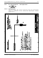
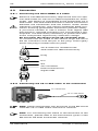
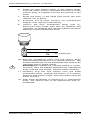
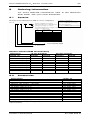
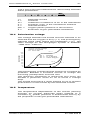
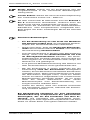
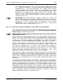
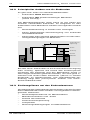
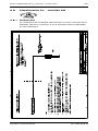
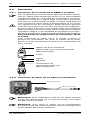
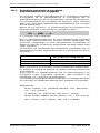
4.2.2 Connecting the VP or AK9 cable to the transmitter
Note: Cable assignment can be found in the METTLER
TOLEDO VP or AK9 cable instruction manual.
Note: For connecting the cable to the terminals of the
transmitter, please refer to the instructions given in the
METTLER TOLEDO transmitter manual.
VP or AK9 cable
O
2
transmitter
VP-6 cable for standard use
AK9 cable for ISM functionality
Plug
Pin
Slit
VP connector
K8S connector for
digital ISM
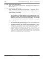
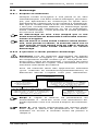
4
.2 Connection
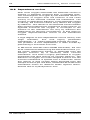
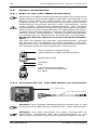
4.2.1 Connecting the InPro 6800 to a cable
Sensors with ISM functionality require the use of a spe-
cial AK9 cable as well as an ISM compatible O
2
trans-
m
itter. The sensor is connected to the transmitter via a
AK9 cable. The AK9 cable ensures a secure connection
between the transmitter and the sensor under harsh
industrial conditions. The robust watertight IP68 con-
nector housing guarantees maximum process safety.
If you have chosen to use a sensor with digital ISM
functionality, the K8S connector will incorporate a pre-
amplifier. It is absolutely necessary to protect this elec-
tronic component against any electrical charge.
Do not touch the sensor at the VP connector plug.
To connect the VP cable to the sensor align the slit of
the VP connector with the pin in the plug. Then tightly
screw the plug to fasten the two parts.
Page is loading ...
Page is loading ...
Page is loading ...
Page is loading ...
Page is loading ...
Page is loading ...
Page is loading ...
Page is loading ...
Page is loading ...
Page is loading ...
Page is loading ...
Page is loading ...
Page is loading ...
Page is loading ...
Page is loading ...
Page is loading ...
Page is loading ...
Page is loading ...
Page is loading ...
Page is loading ...
Page is loading ...
Page is loading ...
Page is loading ...
Page is loading ...
Page is loading ...
Page is loading ...
Page is loading ...
Page is loading ...
Page is loading ...
Page is loading ...
Page is loading ...
Page is loading ...
Page is loading ...
Page is loading ...
Page is loading ...
Page is loading ...
Page is loading ...
Page is loading ...
Page is loading ...
Page is loading ...
Page is loading ...
Page is loading ...
Page is loading ...
Page is loading ...
Page is loading ...
Page is loading ...
Page is loading ...
Page is loading ...
Page is loading ...
Page is loading ...
Page is loading ...
Page is loading ...
Page is loading ...
Page is loading ...
Page is loading ...
Page is loading ...
Page is loading ...
Page is loading ...
Page is loading ...
Page is loading ...
Page is loading ...
Page is loading ...
Page is loading ...
Page is loading ...
Page is loading ...
Page is loading ...
Page is loading ...
Page is loading ...
Page is loading ...
Page is loading ...
Page is loading ...
Page is loading ...
Page is loading ...
Page is loading ...
Page is loading ...
Page is loading ...
Page is loading ...
Page is loading ...
Page is loading ...
Page is loading ...
Page is loading ...
Page is loading ...
Page is loading ...
Page is loading ...
Page is loading ...
Page is loading ...
Page is loading ...
Page is loading ...
Page is loading ...
Page is loading ...
Page is loading ...
Page is loading ...
-
 1
1
-
 2
2
-
 3
3
-
 4
4
-
 5
5
-
 6
6
-
 7
7
-
 8
8
-
 9
9
-
 10
10
-
 11
11
-
 12
12
-
 13
13
-
 14
14
-
 15
15
-
 16
16
-
 17
17
-
 18
18
-
 19
19
-
 20
20
-
 21
21
-
 22
22
-
 23
23
-
 24
24
-
 25
25
-
 26
26
-
 27
27
-
 28
28
-
 29
29
-
 30
30
-
 31
31
-
 32
32
-
 33
33
-
 34
34
-
 35
35
-
 36
36
-
 37
37
-
 38
38
-
 39
39
-
 40
40
-
 41
41
-
 42
42
-
 43
43
-
 44
44
-
 45
45
-
 46
46
-
 47
47
-
 48
48
-
 49
49
-
 50
50
-
 51
51
-
 52
52
-
 53
53
-
 54
54
-
 55
55
-
 56
56
-
 57
57
-
 58
58
-
 59
59
-
 60
60
-
 61
61
-
 62
62
-
 63
63
-
 64
64
-
 65
65
-
 66
66
-
 67
67
-
 68
68
-
 69
69
-
 70
70
-
 71
71
-
 72
72
-
 73
73
-
 74
74
-
 75
75
-
 76
76
-
 77
77
-
 78
78
-
 79
79
-
 80
80
-
 81
81
-
 82
82
-
 83
83
-
 84
84
-
 85
85
-
 86
86
-
 87
87
-
 88
88
-
 89
89
-
 90
90
-
 91
91
-
 92
92
-
 93
93
-
 94
94
-
 95
95
-
 96
96
-
 97
97
-
 98
98
-
 99
99
-
 100
100
-
 101
101
-
 102
102
-
 103
103
-
 104
104
-
 105
105
-
 106
106
-
 107
107
-
 108
108
-
 109
109
-
 110
110
-
 111
111
-
 112
112


Mettler Toledo O2 Sensors InPro6800 and InPro6800 Gas Operating instructions
- Type
- Operating instructions
Ask a question and I''ll find the answer in the document
Finding information in a document is now easier with AI
in other languages
Related papers
-
Mettler Toledo membran-kit for CO2 sensors InPro5000 Operating instructions
-
Mettler Toledo electrolyte and membrane exchange of the InPro® 5000(i) CO2 sensors Operating instructions
-
-
-
-
-
-
-
-
Other documents
-
Hama 00093720 Owner's manual
-
LG K8S User manual
-
Transmitter 418ELPW1K-C Owner's manual
-
-
Case Logic USP2R Datasheet
-
wtw Oxi ML 41 Operating instructions
-
WIKA IS Barrier Operating instructions
-
Advantech INTRAC-305 User manual
-
 Hach orbisphere C1100 User manual
-
VOLTCRAFT CO-60 Operating Instructions Manual
