Page is loading ...

ET900
Intel
®
Core
TM
Duo/Solo 945GM
COM Express (Type II) CPU Module
USER’S MANUAL
Version 1.0

ii
ET900 User’s Manual
Acknowledgments
Award is a registered trademark of Award Software International,
Inc.
PS/2 is a trademark of International Business Machines
Corporation.
Intel and Celeron are registered trademarks of Intel Corporation.
Microsoft Windows is a registered trademark of Microsoft
Corporation.
Winbond is a registered trademark of Winbond Electronics
Corporation.
All other product names or trademarks are properties of their
respective owners.
Attention:
Before installing the CPU heat sink, remove the two protective
sheaths as shown in the figure below.
Note:
Remove the protective
sheath before installation.

ET900 User’s Manual iii
Table of Contents
Introduction.......................................................1
Product Description.............................................................1
Checklist..............................................................................2
ET900 Specifications ..........................................................3
Dimensions..........................................................................4
Installing the Processor .......................................................5
Installing the Memory.........................................................6
Connectors on ET900..........................................................7
J2, J3: COM Express Type 2 Connectors............................ 7
BIOS Setup.......................................................11
Drivers Installation......................................35
Intel Chipset Software Installation Utility.........................36
VGA Drivers Installation ..................................................38
AC97 Codec Audio Driver Installation (IP400 carrier board
only) ..................................................................................40
Intel PRO LAN Drivers Installation..................................42
Marvell LAN Drivers Installation (IP400 carrier board only)
...........................................................................................43

iv
ET900 User’s Manual
The ET900 945GM COM Express CPU Module

INTRODUCTION
ET900 User’s Manual 1
Introduction
Product Description
The ET900 board incorporates the Mobile Intel
®
945GM Express
Chipset for Embedded Computing, consisting of the Intel
®
945GM
Graphic Memory Controller Hub (GMCH) and Intel
®
I/O Controller
Hub 7-M (ICH7-M), an optimized integrated graphics solution with a
533MHz and 667MHz front-side bus. Dimensions of the board are
95mm x 125mm.
The integrated powerful 3D graphics engine, based on Intel® Graphics
Media Accelerator 950 (Intel
®
GMA 950) architecture, operates at core
speeds of up to 400 MHz. It features a low-power design and is validated
with the Intel® Core Duo/Solo on 65nm process. With DDR2 667MHz
SO-DIMM socket on board, the board supports up to 2GB of DDR2
system memory.
Intel
®
Graphics Media Accelerator 950 supports a unique intelligent
memory management scheme called Dynamic Video Memory
Technology (DVMT). DVMT handles diverse applications by providing
the maximum (224MB) availability of system memory for general
computer usage, while supplying additional graphics memory when a
3D-intensive application requests it. The Intel GMA 950 graphics
architecture also takes advantage of the high-performance Intel
processor. Intel GMA 950 graphics supports Dual Independent Display
technology.
The main features of the board are:
Supports COM ETX Type II Module pin-out definitions
Supports Intel
®
Core
TM
Duo/Solo processors
Supports up to 533/667MHz FSB
One DDR2 SDRAM SO-DIMM, Max. 2GB
Intel
®
945GM Express VGA for CRT / LVDS
Intel
®
945GM Integrated VGA; Supports CRT / LVDS
Supports up to six x1 PCI-E, one x16 PCI-E, four PCI

INTRODUCTION
2
ET900 User’s Manual
Checklist
Your ET900 package should include the items listed below.
• The ET900 CPU Module
• This User’s Manual
• 1 CD containing the following:
• Chipset Drivers
• Flash Memory Utility

INTRODUCTION
ET900 User’s Manual 3
ET900 Specifications
Form Factor
COM-ETX w/ Pin-Out Type 2
CPU Type
Intel Core Duo/Solo Mobile Processors
CPU Voltage
0.700V ~ 1.5V
System Speed
Up to 1.66GHz or above
CPU Operate
Frequency
533MHz/667MHz FSB
Cache
2MB
Green /APM
APM1.2
CPU Socket
BGA CPU on board / mPGA 478MT Socket
Chipset
Intel 945GM Chipset
GMCH: 82945GM 1466-pin FCBGA
ICH7M: 82801GBM 652-pin mBGA FWH
BIOS
Award BIOS, support ACPI Function
Memory
DDR2 667/533 SO-DIMM x1 (w/o ECC
function), Max. 2GB
VGA
945GM built-in, supports CRT/S-VIDEO
LVDS
945GM built-in, supports 18+18 bits, single or
dual channel LVDS
TV-Out
Support TV-Out (Composite) and S-Video
LAN
ICH7M built-in 10/100BT MAC + Intel
EP82562ET PHY
USB 2.0
ICH7M built-in USB 2.0 host controller, support
8 ports
Serial ATA Ports
ICH7M built-in SATA controller, supports 2
ports
Parallel IDE
ICH7M built-in one channel Ultra DMA
33/66/100
Audio
ICH7M Built-in Audio controller (AC97 Codec
at carrier board)
Connector to
Carrier Board
Two 220-pin connectors (A-B & C-D)
Watchdog Timer
Yes (256 segments, 0, 1, 2…255 sec/min)
System Voltage
+5V, +3.3V, +12V, 5VSB
Other
Modem Wakeup, LAN Wakeup
Board Size
95mm x 125mm

INTRODUCTION
4
ET900 User’s Manual
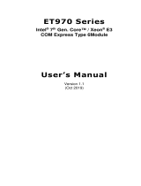
Dimensions

INTRODUCTION
ET900 User’s Manual 5
Installing the Processor
The ET900 is available with a processor socket on board or with an
Intel® processor on board. In the case that your ET900 comes a Socket
479 processor socket for Intel
®
Pentium
®
M or Celeron
®
M processors,
follow the instructions below regarding the processor installation.
The processor socket comes with a screw to secure the processor. As
shown in the left picture below, loosen the screw first before inserting
the processor. Place the processor into the socket by making sure the
notch on the corner of the processor corresponds with the notch on the
inside of the socket. Once the processor has slide into the socket, fasten
the screw. Refer to the figures below.
NOTE:
Ensure that the CPU heat sink and the CPU top surface are in
total contact to avoid CPU overheating problem that would
cause your system to hang or be unstable.

INTRODUCTION
6
ET900 User’s Manual
Installing the Memory
The ET900 COM Express CPU module accommodates 200-pin
DDR2-533 and DDR2-667 SODIMM memory modules with capacities
up to 1GB. Non-ECC is supported.
Installing and Removing Memory Modules
To install the DDR2 modules, locate the memory slot on the board and
perform the following steps:
1. Hold the DDR2 module so that the key of the DDR2 module align
with those on the memory slot. Insert the module into the socket at a
slight angle (approximately 30 degrees). Note that the socket and
module are both keyed, which means that the module can be installed
only in one direction.
2. To seat the memory module into the socket, apply firm and even
pressure to each end of the module until you feel it slip down into the
socket.
3. With the module properly seated in the socket, rotate the module
downward. Continue pressing downward until the clips at each end
lock into position.
4. To remove the DDR2 module, press the clips with both hands.

INTRODUCTION
ET900 User’s Manual 7
Connectors on ET900
J2, J3: COM Express Type 2 Connectors
The Type 2 connectors come in two 220-pin 0.5mm pitch receptacles.
They include PCI, IDE, GBE and up to 22 general-purpose PCIE lanes
(PCIE 0-5 and PCIE 16-31). For most Type 2 implementations, it is
expected that PCIE lanes 16-31 are used for graphics. Hence they are
designated PEG lanes 0-15 in the following table. Modules
implementing Pin out Type 2, such as the ET900, uses the pin-out
shown.

INTRODUCTION
8
ET900 User’s Manual
Row A Row B Row C Row D
Pin Signal Pin Signal Pin Signal Pin Signal
A1 GND (FIXED) B1 GND (FIXED) C1 GND (FIXED) D1 GND (FIXED)
A2 NC B2 GBE0_ACT# C2 IDE_D7 D2 IDE_D5
A3 NC B3 LPC_FRAME# C3 IDE_D6 D3 IDE_D10
A4 GBE0_LINK100# B4 LPC_AD0 C4 IDE_D3 D4 IDE_D11
A5 NC B5 LPC_AD1 C5 IDE_D15 D5 IDE_D12
A6 NC B6 LPC_AD2 C6 IDE_D8 D6 IDE_D4
A7 NC B7 LPC_AD3 C7 IDE_D9 D7 IDE_D0
A8 GBE0_LINK# B8 LPC_DRQ0# C8 IDE_D2 D8 IDE_REQ
A9 GBE0_MDI1- B9 LPC_DRQ1# C9 IDE_D13 D9 IDE_IOW#
A10 GBE0_MDI1+ B10 LPC_CLK C10 IDE_D1 D10 IDE_ACK#
A11 GND (FIXED) B11 GND (FIXED) C11 GND (FIXED) D11 GND (FIXED)
A12 GBE0_MDI0- B12 PWRBTN# C12 IDE_D14 D12 IDE_IRQ
A13 GBE0_MDI0+ B13 SMB_CK C13 IDE_IORDY D13 IDE_A0
A14 NC B14 SMB_DAT C14 IDE_IOR# D14 IDE_A1
A15 SUS_S3# B15 SMB_ALERT# C15 PCI_PME# D15 IDE_A2
A16 SATA0_TX+ B16 SATA1_TX+ C16 PCI_GNT2# D16 IDE_CS1#
A17 SATA0_TX- B17 SATA1_TX- C17 PCI_REQ2# D17 IDE_CS3#
A18 SUS_S4# B18 SUS-STAT# C18 PCI_GNT1# D18 IDE_RESET#
A19 SATA0_RX+ B19 SATA1_RX+ C19 PcI_REQ1# D19 PCI_GNT3#
A20 SATA0_RX- B20 SATA1_RX- C20 PCI_GNT0# D20 PCI_REQ3#
A21 GND (FIXED) B21 GND (FIXED) C21 GND (FIXED) D21 GND (FIXED)
A22 NC B22 NC C22 PCI_REQ0# D22 PCI_AD1
A23 NC B23 NC C23 PCI_RESET# D23 PCI_AD3
A24 SUS_S5# B24 NC C24 PCI_AD0 D24 PCI_AD5
A25 NC B25 NC C25 PCI_AD2 D25 PCI_AD7
A26 NC B26 NC C26 PCI_AD4 D26 PCI_C/BE0#
A27 BATLOW# B27 NC C27 PCI_AD6 D27 PCI_AD9
A28 ATA_ACT# B28 AC_SDIN2 C28 PCI_AD8 D28 PCI_AD11
A29 AC_SYNC B29 AC_SDIN1 C29 PCI_AD10 D29 PCI_AD13
A30 SC_RST# B30 AC_SDIN0 C30 PCI_AD12 D30 PCI_AD15
A31 GND (FIXED) B31 GND (FIXED) C31 GND (FIXED) D31 GND (FIXED)
A32 AC_BITCLK B32 SPKR C32 PCI_AD13 D32 PCI_PAR
A33 AC_SDOUT B33 I2C_CK C33 PCI_C/BE1# D33 PCI_SERR#
A34 NC B34 I2C_DAT C34 PCI_PERR# D34 PCI_STOP#
A35 THRMTRIP# B35 THRM# C35 PCI_LOCK# D35 PCI_TRDY#
A36 USB6- B36 USB7- C36 PCI_DEVSEL# D36 PCI_FRAME#
A37 USB6+ B37 USB7+ C37 PCI_IRDY# D37 PCI_AD16
A38 USB_6_7_OC# B38 USB_4_5_OC# C38 PCI_C/BE2# D38 PCI_AD18
A39 USB4- B39 USB5- C39 PCI_AD17 D39 PCI_AD20
A40 USB4+ B40 USB5+ C40 PCI_AD19 D40 PCI_AD22
A41 GND (FIXED) B41 GND (FIXED) C41 GND (FIXED) D41 GND (FIXED)
A42 USB2- B42 USB3- C42 PCI_AD21 D42 PCI_AD24
A43 USB2+ B43 USB3+ C43 PCI_AD23 D43 PCI_AD26
A44 USB_2_3_OC# B44 USB_0_1_OC# C44 PCI_C/BE3# D44 PCI_AD28
A45 USB0- B45 USB1- C45 PCI_AD25 D45 PCI_AD30
A46 USB0+ B46 USB1+ C46 PCI_AD27 D46 PCI_IRQC#
A47 VCC_RTC B47
EXCD1_PERTST#
C47 PCI_AD29 D47 PCI_IRQD#
A48 EXCD0_PERST# B48 EXCD1_CPPE# C48 PCI_AD31 D48 NC
A49 EXCD0CPPE# B49 SYS_RESET# C49 PCI_IRQA# D49 NC
A50 LPC_SERIRQ B50 CB_RESET# C50 PCI_IRQB3 D50 PCI_CLK

INTRODUCTION
ET900 User’s Manual 9
Row A Row B Row C Row D
Pin Signal Pin Signal Pin Signal Pin Signal
A51 GND (FIXED) B51 GND (FIXED) C51 GND (FIXED) D51 GND (FIXED)
A52 NC B52 NC C52 PEG_RX0+ D52 PEG_TX0+
A53 NC B53 NC C53 PEG_RX0- D53 PEG_TX0-
A54 GPI0 B54 GPO1 C54 NC D54 PEG_LANE_RV#
A55 NC B55 NC C55 PEG_RX1+ D55 PEG_TX1+
A56 NC B56 NC C56 PEG_RX1- D56 PEG_TX1-
A57 GND B57 GPO2 C57 NC D57 NC
A58 PCIE_TX3+ B58 PCIE_RX3+ C58 PEG_RX2+ D58 PEG_TX2+
A59 PCIE_TX3- B59 PCIE_RX3- C59 PEG_RX2- D59 PEG_TX2-
A60 GND (FIXED) B60 GND (FIXED) C60 GND (FIXED) D60 GND (FIXED)
A61 PCIE_TX2+ B61 PCIE_RX2+ C61 PEG_RX3+ D61 PEG_TX3+
A62 PCIE_TX2- B62 PCIE_RX2- C62 PEG_RX3- D62 PEG_TX3-
A63 GPI1 B63 GPO3 C63 RSVD D63 RSVD
A64 PCIE_TX1+ B64 PCIE_RX1+ C64 RSVD D64 RSVD
A65 PCIE_TX1- B65 PCIE_RX1- C65 PEG_RX4+ D65 PEG_TX4+
A66 GND B66 WAKE0# C66 PEG_RX4- D66 PEG_TX4-
A67 GPI2 B67 WAKE1# C67 RSVD D67 GND
A68 PCIE_TX0+ B68 PCIE_RX0+ C68 PEG_RX5+ D68 PEG_TX5+
A69 PCIE_TX0- B69 PCIE_RX0- C69 PEG_RX5- D69 PEG_TX5-
A70 GND (FIXED) B70 GND (FIXED) C70 GND (FIXED) D70 GND (FIXED)
A71 LVDS_A0+ B71 LVDS_B0+ C71 PEG_RX6+ D71 PEG_TX9+
A72 LVDS_A0- B72 LVDS_B0- C72 PEG_RX6- D72 PEG_TX9-
A73 LVDS_A1+ B73 LVDS_B1+ C73 SDVO_DATA D73 SDVO_CLK
A74 LVDS_A1- B74 LVDS_B1- C74 PEG_RX7+ D74 PEG_TX7+
A75 LVDS_A2+ B75 LVDS_B2+ C75 PEG_RX7- D75 PEG_TX7-
A76 LVDS_A2- B76 LVDS_B2- C76 GND D76 GND
A77 LVDS_VDD_EN B77 NC C77 RSVD D77 IDE_CBLID#
A78 NC B78 NC C78 PEG_RX8+ D78 PEG_TX8+
A79 NC B79 LVDS_BKLT_EN C79 PEG_RX8- D79 PEG_TX8-
A80 GND (FIXED) B80 GND (FIXED) C80 GND (FIXED) D80 GND (FIXED)
A81 LVDS_A_CK+ B81 LVDS_B_CK+ C81 PEG_RX9+ D81 PEG_TX9+
A82 LVDS_A_CK- B82 LVDS_B_CK- C82 PEG_RX9- D82 PEG_TX9-
A83 LVDS_I2C_CK B83 LVDS_BKLT_Ctrl C83 RSVD D83 RSVD
A84 LVDS_I2C_DAT B84 VCC_5V_SBY C84 GND D84 GND
A85 GPI3 B85 VCC_5V_SBY C85 PEG_RX10+ D85 PEG_TX10+
A86 KBD_RSD# B86 VCC_5V_SBY C86 PEG_RX10- D86 PEG_TX10-
A87 KBD_A20GATE B87 VCC_5V_SBY C87 GND D87 GND
A88 PCIE0_CK_REF+ B88 RSVD C88 PEG_RX11+ D88 PEG_TX11+
A89 PCIE0_CK_REF- B89 VGA_RED C89 PEG_RX11- D89 PEG_TX11-
A90 GND (FIXED) B90 GND (FIXED) C90 GND (FIXED) D90 GND (FIXED)
A91 RSVD B91 VGA_GRN C91 PEG_RX12+ D91 PEG_TX12+
A92 RSVD B92 VGA_BLU C92 PEG_RX12- D92 PEG_TX12-
A93 GPO0 B93 VGA_HSYNC C93 GND D93 GND
A94 RSVD B94 VGA_VSYNC C94 PEG_RX13+ D94 PEG_TX13+
A95 RSVD B95 VGA_I2C_CK C95 PEG_RX13- D95 PEG_TX13-
A96 GND B96 VGA_I2C_DATA C96 GND D96 GND
A97 VCC_12V B97 TV_DAC_A C97 RSVD D97 PEG_ENABLE#
A98 VCC_12V B98 TV_DAC_B C98 PEG_RX14+ D98 PEG_TX14+
A99 VCC_12V B99 TV_DAC_C C99 PEG_RX14- D99 PEG_TX14-
A100 GND (FIXED) B100 GND (FIXED) C100 GND (FIXED) D100 GND (FIXED)
A101 VCC_12V B101 VCC_12V C101 PEG_RX15+ D101 PEG_TX15+
A103 VCC_12V B103 VCC_12V C103 PEG_RX15- D103 PEG_TX15-
A103 VCC_12V B103 VCC_12V C103 GND D103 GND
A104 VCC_12V B104 VCC_12V C104 VCC_12V D104 VCC_12V
A105 VCC_12V B105 VCC_12V C105 VCC_12V D105 VCC_12V
A106 VCC_12V B106 VCC_12V C106 VCC_12V D106 VCC_12V
A107 VCC_12V B107 VCC_12V C107 VCC_12V D107 VCC_12V
A108 VCC_12V B108 VCC_12V C108 VCC_12V D108 VCC_12V
A109 VCC_12V B109 VCC_12V C109 VCC_12V D109 VCC_12V
A110 GND (FIXED) B110 GND (FIXED) C110 GND (FIXED) D110 GND (FIXED)

INTRODUCTION
10
ET900 User’s Manual
This page is intentionally left blank.

BIOS SETUP
ET900 User’s Manual 11
BIOS Setup
This chapter describes the different settings available in the Award
BIOS that comes with the board. The topics covered in this chapter are
as follows:
BIOS Introduction........................................................................ 12
BIOS Setup................................................................................... 12
Standard CMOS Setup ................................................................. 14
Advanced BIOS Features............................................................. 17
Advanced Chipset Features.......................................................... 20
Integrated Peripherals................................................................... 23
Power Management Setup............................................................ 27
PNP/PCI Configurations .............................................................. 30
PC Health Status........................................................................... 31
Frequency/Voltage Control.......................................................... 32
Load Fail-Safe Defaults................................................................ 33
Load Optimized Defaults ............................................................. 33
Set Supervisor/User Password...................................................... 33
Save & Exit Setup ........................................................................ 33
Exit Without Saving..................................................................... 33

BIOS SETUP
12
ET900 User’s Manual
BIOS Introduction
The Award BIOS (Basic Input/Output System) installed in your
computer system’s ROM supports Intel processors. The BIOS provides
critical low-level support for a standard device such as disk drives, serial
ports and parallel ports. It also adds virus and password protection as
well as special support for detailed fine-tuning of the chipset controlling
the entire system.
BIOS Setup
The Award BIOS provides a Setup utility program for specifying the
system configurations and settings. The BIOS ROM of the system stores
the Setup utility. When you turn on the computer, the Award BIOS is
immediately activated. Pressing the <Del> key immediately allows you
to enter the Setup utility. If you are a little bit late pressing the <Del>
key, POST (Power On Self Test) will continue with its test routines, thus
preventing you from invoking the Setup. If you still wish to enter Setup,
restart the system by pressing the ”Reset” button or simultaneously
pressing the <Ctrl>, <Alt> and <Delete> keys. You can also restart by
turning the system Off and back On again. The following message will
appear on the screen:
Press <DEL> to Enter Setup
In general, you press the arrow keys to highlight items, <Enter> to
select, the <PgUp> and <PgDn> keys to change entries, <F1> for help
and <Esc> to quit.
When you enter the Setup utility, the Main Menu screen will appear on
the screen. The Main Menu allows you to select from various setup
functions and exit choices.

BIOS SETUP
ET900 User’s Manual 13
Phoenix - AwardBIOS CMOS Setup Utility
Standard CMOS Features Frequency/Voltage Control
Advanced BIOS Features Load Fail-Safe Defaults
Advanced Chipset Features Load Optimized Defaults
Integrated Peripherals Set Supervisor Password
Power Management Setup Set User Password
PnP/PCI Configurations Save & Exit Setup
PC Health Status Exit Without Saving
ESC : Quit Ç È Æ Å : Select Item
F10 : Save & Exit Setup
Time, Date, Hard Disk Type…
The section below the setup items of the Main Menu displays the control
keys for this menu. At the bottom of the Main Menu just below the
control keys section, there is another section, which displays information
on the currently highlighted item in the list.
Note:
If the system cannot boot after making and saving system
changes with Setup, the Award BIOS supports an override to
the CMOS settings that resets your system to its default.
Warning:
It is strongly recommended that you avoid making any
changes to the chipset defaults. These defaults have been
carefully chosen by both Award and your system
manufacturer to provide the ab
s
olute maximum performance
and reliability. Changing the defaults could cause the system
to become unstable and crash in some cases.

BIOS SETUP
14
ET900 User’s Manual
Standard CMOS Setup
“Standard CMOS Setup” choice allows you to record some basic
hardware configurations in your computer system and set the system
clock and error handling. If the board is already installed in a working
system, you will not need to select this option. You will need to run the
Standard CMOS option, however, if you change your system hardware
configurations, the onboard battery fails, or the configuration stored in
the CMOS memory was lost or damaged.
Phoenix - AwardBIOS CMOS Setup Utility
Standard CMOS Features
Date (mm:dd:yy) Wed, Apr 28, 2004 Item Help
Time (hh:mm:ss) 00 : 00 : 00 Menu Level >
IDE Channel 0 Master None
IDE Channel 0 Slave None
IDE Channel 1 Master None
Change the day, month,
Year and century
IDE Channel 1 Slave None
Drive A 1.44M, 3.5 in.
Drive B None
Video EGA/VGA
Halt On All Errors
Base Memory 640K
Extended Memory 129024K
Total Memory 130048K
At the bottom of the menu are the control keys for use on this menu. If
you need any help in each item field, you can press the <F1> key. It will
display the relevant information to help you. The memory display at the
lower right-hand side of the menu is read-only. It will adjust
automatically according to the memory changed. The following
describes each item of this menu.
Date
The date format is:
Day : Sun to Sat
Month : 1 to 12
Date : 1 to 31
Year : 1999 to 2099

BIOS SETUP
ET900 User’s Manual 15
To set the date, highlight the “Date” field and use the PageUp/
PageDown or +/- keys to set the current time.
Time
The time format is:
Hour : 00 to 23
Minute : 00 to 59
Second : 00 to 59
To set the time, highlight the “Time” field and use the <PgUp>/ <PgDn>
or +/- keys to set the current time.
IDE Channel Master/Slave
The onboard PCI IDE connector provides Primary and Secondary
channels for connecting up to two IDE hard disks or other IDE devices.
Press <Enter> to configure the hard disk. The selections include Auto,
Manual, and None. Select ‘Manual’ to define the drive information
manually. You will be asked to enter the following items.
CYLS : Number of cylinders
HEAD : Number of read/write heads
PRECOMP : Write precompensation
LANDING ZONE : Landing zone
SECTOR : Number of sectors
The Access Mode selections are as follows:
CHS (HD < 528MB)
LBA (HD > 528MB and supports
Logical Block Addressing)
Large (for MS-DOS only)
Auto
Remarks: The main board supports two serial ATA ports and are
represented in this setting as IDE Channel 0.
Drive A / Drive B
These fields identify the types of floppy disk drive A or drive B that has
been installed in the computer. The available specifications are:
360KB
5.25 in.
1.2MB
5.25 in.
720KB
3.5 in.
1.44MB
3.5 in.
2.88MB
3.5 in.

BIOS SETUP
16
ET900 User’s Manual
Video
This field selects the type of video display card installed in your system.
You can choose the following video display cards:
EGA/VGA For EGA, VGA, SEGA, SVGA
or PGA monitor adapters. (default)
CGA 40 Power up in 40 column mode.
CGA 80 Power up in 80 column mode.
MONO For Hercules or MDA adapters.
Halt On
This field determines whether or not the system will halt if an error is
detected during power up.
No errors The system boot will not be halted for any error
that may be detected.
All errors Whenever the BIOS detects a non-fatal error,
the system will stop and you will be prompted.
All, But Keyboard The system boot will not be halted for a
keyboard error; it will stop for all other errors
All, But Diskette The system boot will not be halted for a disk
error; it will stop for all other errors.
All, But Disk/Key The system boot will not be halted for a key-
board or disk error; it will stop for all others.
/