Page is loading ...

ET981 Series
Intel® 13th Gen. Core™
COM Express Type 6 Module
User’s Manual
Version 1.0
(January 2024)

ii
ET981 Series User’s Manual
Copyright
© 2024 IBASE Technology, Inc. All rights reserved.
No part of this publication may be reproduced, copied, stored in a retrieval
system, translated into any language or transmitted in any form or by any
means, electronic, mechanical, photocopying, or otherwise, without the prior
written consent of IBASE Technology, Inc. (hereinafter referred to as
“IBASE”).
Disclaimer
IBASE reserves the right to make changes and improvements to the
products described in this document without prior notice. While every effort
has been made to ensure the accuracy of the information in this document,
IBASE does not guarantee that it is free of errors.
IBASE assumes no liability for incidental or consequential damages that may
arise from the misapplication or inability to use the product or the information
contained herein, nor for any infringements of rights of third parties, which
may result from its use.
Trademarks
All the trademarks, registrations and brands mentioned herein are used for
identification purposes only and may be trademarks and/or registered
trademarks of their respective owners.

ET981 Series User’s Manual
iii
Compliance
This product has passed CE tests for environmental specifications and limits.
This product is in accordance with the directives of the European Union (EU).
In a domestic environment, this product may cause radio interference in
which case users may be required to take adequate measures.
This product has been tested and found to comply with the limits for a Class
B device, pursuant to Part 15 of the FCC Rules. These limits are designed to
provide reasonable protection against harmful interference in a residential
installation. This equipment generates, uses and can radiate radio frequency
energy and, if not installed and used in accordance with manufacturer’s
instructions, may cause harmful interference to radio communications.
WEEE
This product must not be disposed of as normal household
waste, in accordance with the EU directive of for waste
electrical and electronic equipment (WEEE - 2012/19/EU).
Instead, it should be disposed of by returning it to a
municipal recycling collection point. Check local
regulations for disposal of electronic products.
Green IBASE
This product is compliant with the current RoHS
restrictions and prohibits use of the following substances in
concentrations exceeding 0.1% by weight (1000 ppm)
except for cadmium, limited to 0.01% by weight (100 ppm).
• Lead (Pb)
• Mercury (Hg)
• Cadmium (Cd)
• Hexavalent chromium (Cr6+)
• Polybrominated biphenyls (PBB)
• Polybrominated diphenyl ether (PBDE)

iv
ET981 Series User’s Manual
Important Safety Information
Carefully read the precautions before using the board.
Environmental conditions:
• Use this product in environments with ambient temperatures between
0˚C and 60˚C.
• Do not leave this product in an environment where the storage
temperature may be below -20° C or above 80° C. To prevent damage,
the product must be used in a controlled environment.
Care for your IBASE products:
• Before cleaning the PCB, unplug all cables and remove the battery.
• Clean the PCB with a circuit board cleaner or degreaser, or use cotton
swabs and alcohol.
• Vacuum the dust with a computer vacuum cleaner to prevent the fan
from being clogged.
WARNING
Attention during use:
• Do not use this product near water.
• Do not spill water or any other liquids on this product.
• Do not place heavy objects on the top of this product.
Anti-static precautions
• Wear an anti-static wrist strap to avoid electrostatic discharge.
• Place the PCB on an anti-static kit or mat.
• Hold the edges of PCB when handling.
• When handling the product, touch the edges of non-metallic
components rather than the surface of the PCB.
• Ground yourself by touching a grounded conductor or a grounded bit of
metal frequently to discharge any static.
CAUTION
Danger of explosion if the internal lithium-ion battery is replaced by an
incorrect type. Replace only with the same or equivalent type recommended
by the manufacturer. Dispose of used batteries according to the
manufacturer’s instructions or recycle them at a local recycling facility or
battery collection point.

ET981 Series User’s Manual
v
Warranty Policy
• IBASE standard products:
24-month (2-year) warranty from the date of shipment. If the date of
shipment cannot be ascertained, the product serial numbers can be
used to determine the approximate shipping date.
• Third-party parts:
12-month (1-year) warranty from delivery for the third-party parts that
are not manufactured by IBASE, such as CPU, CPU cooler, memory,
storage devices, power adapter, panel and touchscreen.
* However, products that fail due to misuse, accident, improper
installation, or unauthorized repair shall be considered out of warranty,
and customers will be billed for repair and shipping charges.
Technical Support & Services
1. Visit the IBASE website at www.ibase.com.tw to find the latest
information about the product.
2. If you need any further assistance from your distributor or sales
representative, prepare the following information of your product and
elaborate upon the problem.
• Product model name
• Product serial number
• Detailed description of the problem
• The error messages in text or in screenshots if there is any
• The arrangement of the peripherals
• Software in use (such as OS and application software, including the
version numbers)
3. If repair service is required, please login in to the RMA system of the
website or and contact your distributor or sales representative for
assistance.

vi
ET981 Series User’s Manual
Table of Contents
Chapter 1 General Information..................................................... 1
1.1 Introduction ............................................................................................ 2
1.2 Features ................................................................................................. 2
1.3 Packing List ........................................................................................... 3
1.4 Specifications ......................................................................................... 3
1.5 Block Diagram ....................................................................................... 5
1.6 Board View ............................................................................................ 6
1.7 Dimensions ............................................................................................ 8
Chapter 2 Hardware Configuration .......................................... 9
2.1 Installations .......................................................................................... 10
2.2 Switch & Connector Locations ............................................................. 11
2.3 Switch & Connector Quick Reference ................................................. 12
Chapter 3 Drivers Installation ............................................. 17
3.1 Introduction .......................................................................................... 18
3.2 Intel® Chipset Software Installation Utility ............................................ 18
3.3 Graphics Driver Installation .................................................................. 20
3.4 HD Audio Driver Installation ................................................................. 22
3.5 LAN Driver Installation ......................................................................... 24
3.6 Intel® Management Engine Drivers Installation .................................. 26
Chapter 4 BIOS Setup ......................................................... 28
4.1 Introduction .......................................................................................... 29
4.2 BIOS Setup .......................................................................................... 29
4.3 Main Settings ....................................................................................... 30
4.4 Advanced Settings ............................................................................... 31
4.5 Chipset Settings ................................................................................... 44
4.6 Security Settings .................................................................................. 47
4.7 Boot Settings ....................................................................................... 48
4.8 Save & Exit Settings ............................................................................ 49
Appendix ........................................................................................ 50
A. I/O Port Address Map .......................................................................... 51
B. Interrupt Request Lines (IRQ).............................................................. 53
C. Watchdog Timer Configuration ............................................................ 54

1
Chapter 1
General Information
The information provided in this chapter includes:
• Features
• Packing List
• Specifications
• Block Diagram
• Board View
• Dimensions

2
ET981 Series User’s Manual
1.1 Introduction
The ET981 COM Express module offers exceptional performance with 13th
Gen Intel® P-series Core™ i7/i5/i3 processors integrated onboard. It
provides robust memory support with two DDR4-3200 SO-DIMM sockets,
allowing a maximum of 64GB RAM. Connectivity is a breeze with features
like 2.5 GbE Ethernet, multiple USB ports, SATA III support, and COM ports
for versatile connections. Users can enjoy up to three independent displays
using HDMI, DP, VGA, LVDS, or eDP options. Additional features include
wide temperature support, digital I/O, TPM 2.0 for enhanced security, a
watchdog timer, and expansion capabilities through 1x PCI-E(x16), 1x
PCI-E(x4), and 4x PCI-E(x1) signals to a carrier board.
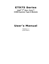
ET981
1.2 Features
● Onboard 13th Gen Intel® Core™ i7/i5/i3 processors
● 2x DDR4-3200 SO-DIMM sockets, Max. 64GB
● Onboard 2.5 GbE
● Supports 3x independent displays - HDMI / DP / VGA / LVDS or eDP
● 4x USB 3.2, 8x USB 2.0, 2x SATA III, 2x COM
● 1x PCIe(x16) [Gen.4 (8x) / Gen 4 (2x PCIe(4x)], 1x PCIe(x4) (Gen. 3),
4x PCI-E(x1) to carrier board
**Only one PCI-E (x8) signal from Raptor Lake-P 28W/15W CPU skus**
● Digital I/O, TPM (2.0), Watchdog timer
**

General Information
ET981 Series User’s Manual
3
1
1.3 Packing List
Your ET981 package should include the items listed below. If any of the
items below is missing, contact the distributor or dealer from whom you
purchased the product.
• ET981 COM Express Module x 1
• Disk (including drivers and flash memory utility) x 1
• This User’s Manual x 1
1.4 Specifications
Product Models
ET981LV-I7P - Intel® i7-1370PE with LVDS support
ET981LV-I5U - Intel® i5-1335UE with LVDS support
ET981-I5U - Intel® i5-1335UE with eDP support
ET981LV-I5P - Intel® i5-1340PE with LVDS support
ET981LV-I3P - Intel® i3-1320PE with LVDS support
ET981LV-I7PRE - Intel® i7-1370PRE with LVDS support
System
Operating
System
Windows 10 (64-bit)
Memory
2x DDR4-3200 SO-DIMM sockets, Max. 64GB
Graphics
13th Gen Intel® Core™ P-series processor integrated graphics
Video Output
HDMI, DisplayPort, VGA, LVDS or eDP on carrier board
Ethernet
Intel® I226LM 2.5 GbE RJ45 on carrier board
(Intel® I226IT 2.5 GbE for ET981LV-I7PRE, supports iAMT)
Super I/O
Fintek F81804U-I
USB 2.0
8x USB 2.0 via carrier board
USB 3.X
4x USB 3.2 (Gen 2) via carrier board
Serial ATA
2x SATA III via carrier board
Audio
Built-in HD Audio controller
Expansion Slot
1x PCIe(x16) [Gen.4 (8x) / Gen 4 (2x PCIe(4x)], 1x PCIe(x4)
(Gen. 3), 4x PCI-E(x1) to carrier board

4
ET981 Series User’s Manual
Watchdog
Timer
Yes (256 segments, 0, 1, 2…255 sec / min)
BIOS
AMI BIOS
H/W Monitor
Yes
TPM
TPM (2.0)
Dimensions
125 x 95 mm ( 4.92” x 3.74”)
Certification
CE, FCC Class B
RoHS
Yes
Environment
Temperature
• Operating: 0 ~ 60 °C (32 ~ 140 °F)
-40 ~ 85 °C (ET981LV-I7PRE)
Storage: -20 ~ 80 °C (-4 ~ 176 °F)
Relative
Humidity
10 ~ 90 %, non-condensing
All specifications are subject to change without prior notice.

General Information
ET981 Series User’s Manual
5
1
1.5 Block Diagram

6
ET981 Series User’s Manual
1.6 Board View
Top View

General Information
ET981 Series User’s Manual
7
1
Bottom View
*The pictures are for reference only. Some minor components may differ.

8
ET981 Series User’s Manual
1.7 Dimensions
Unit: mm

9
Chapter 2
Hardware Configuration
This section provides information on jumper settings and
connectors on the ET981 in order to set up a workable system.
On top of that, you will also need to install crucial pieces such as
the CPU and the memory before using the product. The topics
covered are:
• Installations
• Switch and connector locations and information

10
ET981 Series User’s Manual
2.1 Installations
2.1.1 Installing the Memory
To replace or install a memory module, locate the memory slot (J2, J4) on the
board and perform the following steps:
1. Align the key of the memory module with that on the memory slot and
insert the module slantwise.
2. Gently push the module in an upright position until the clips of the slot
close to hold the module in place when the module touches the bottom
of the slot.
To remove the module, press the clips outwards simultaneously with both
hands, and the module will pop up.

Hardware Configuration
ET981 Series User’s Manual
11
2
2.2 Switch & Connector Locations
Top View
Bottom View
Remarks:
SW1: ATX / AT Mode
J2, J4: SO-DIMM Sockets
COM_E_AB1, COM_E_CD1: COM Express Module Type 6 Connector

12
ET981 Series User’s Manual
2.3 Switch & Connector Quick Reference
Function
Jumper
Page
ATX / AT Mode
SW1
12
COM Express Module
Type 6 Connector
(COM_E_AB1,
COM_E_CD1)
13
2.3.1 ATX / AT Mode (SW1)
Function
Pin closed
Illustration
ATX
(default)
P1-OFF
AT
P1-ON
Note: AT: Auto power on; ATX: Manual power on

Hardware Configuration
ET981 Series User’s Manual
13
2
2.3.2 COM Express Module Type 6 Connector
Row A
Row B
Row C
Row D
Pin
Signal
Pin
Signal
Pin
Signal
Pin
Signal
A1
GND (FIXED)
B1
GND (FIXED)
C1
GND (FIXED)
D1
GND (FIXED)
A2
GBE0_MDI3-
B2
GBE0_ACT#
C2
GND
D2
GND
A3
GBE0_MDI3+
B3
LPC_FRAME#
C3
USB_SSRX0-
D3
USB_SSTX0-
A4
GBE0_LINK100#
B4
LPC_AD0
C4
USB_SSRX0+
D4
USB_SSTX0+
A5
GBE0_LINK1000#
B5
LPC_AD1
C5
GND
D5
GND
A6
GBE0_MDI2-
B6
LPC_AD2
C6
USB_SSRX1-
D6
USB_SSTX1-
A7
GBE0_MDI2+
B7
LPC_AD3
C7
USB_SSRX1+
D7
USB_SSTX1+
A8
GBE0_LINK#
B8
LPC_DRQ0#
C8
GND
D8
GND
A9
GBE0_MDI1-
B9
NC
C9
USB_SSRX2-
D9
USB_SSTX2-
A10
GBE0_MDI1+
B10
LPC_CLK
C10
USB_SSRX2+
D10
USB_SSTX2+
A11
GND (FIXED)
B11
GND (FIXED)
C11
GND (FIXED)
D11
GND (FIXED)
A12
GBE0_MDI0-
B12
PWRBTN#
C12
USB_SSRX3-
D12
USB_SSTX3-
A13
GBE0_MDI0+
B13
SMB_CK
C13
USB_SSRX3+
D13
USB_SSTX3+
A14
GBE0_CTREF
B14
SMB_DAT
C14
GND
D14
GND
A15
SUS_S3#
B15
SMB_ALERT#
C15
NC
D15
DDI1_CTRLCLK_A
UX+
A16
SATA0_TX+
B16
SATA1_TX+
C16
NC
D16
DDI1_CTRLDATA_
AUX-
A17
SATA0_TX-
B17
SATA1_TX-
C17
RSVD
D17
RSVD
A18
SUS_S4#
B18
NC
C18
RSVD
D18
RSVD
A19
SATA0_RX+
B19
SATA1_RX+
C19
PCIE_RX6+
D19
PCIE_TX6+
A20
SATA0_RX-
B20
SATA1_RX-
C20
PCIE_RX6-
D20
PCIE_TX6-
A21
GND (FIXED)
B21
GND (FIXED)
C21
GND (FIXED)
D21
GND (FIXED)
A22
NC
B22
NC
C22
PCIE_RX7+
D22
PCIE_TX7+
A23
NC
B23
NC
C23
PCIE_RX7-
D23
PCIE_TX7-
A24
SUS_S5#
B24
PWR_OK
C24
DDI1_HPD
D24
RSVD
A25
NC
B25
NC
C25
NC
D25
RSVD
A26
NC
B26
NC
C26
NC
D26
DDI1_PAIR0+
A27
BATLOW#
B27
WDT
C27
RSVD
D27
DDI1_PAIR0-
A28
SATA_ACT#
B28
NC
C28
RSVD
D28
RSVD
A29
HDA_SYNC
B29
NC
C29
NC
D29
DDI1_PAIR1+
A30
HDA_RST#
B30
HDA_SDIN0
C30
NC
D30
DDI1_PAIR1-

14
ET981 Series User’s Manual
Row A
Row B
Row C
Row D
Pin
Signal
Pin
Signal
Pin
Signal
Pin
Signal
A31
GND (FIXED)
B31
GND (FIXED)
C31
GND (FIXED)
D31
GND (FIXED)
A32
HDA_BITCLK
B32
NC
C32
DDI2_CTRLCLK_AUX+
D32
DDI1_PAIR2+
A33
HDA_SDOUT
B33
I2C_CK
C33
DDI2_CTRLDATA_AUX-
D33
DDI1_PAIR2-
A34
BIOS_DIS0#
B34
I2C_DAT
C34
DDI2_DDC_AUX_SEL
D34
DDI1_DDC_AUX_SEL
A35
THRMTRIP#
B35
THRM#
C35
RSVD
D35
RSVD
A36
USB6-
B36
USB7-
C36
DDI3_CTRLCLK_AUX+
D36
DDI1_PAIR3+
A37
USB6+
B37
USB7+
C37
DDI3_CTRLDATA_AUX-
D37
DDI1_PAIR3-
A38
USB_6_7_OC#
B38
USB_4_5_OC#
C38
DDI3_DDC_AUX_SEL
D38
RSVD
A39
USB4-
B39
USB5-
C39
DDI3_PAIR0+
D39
DDI2_PAIR0+
A40
USB4+
B40
USB5+
C40
DDI3_PAIR0-
D40
DDI2_PAIR0-
A41
GND (FIXED)
B41
GND (FIXED)
C41
GND (FIXED)
D41
GND (FIXED)
A42
USB2-
B42
USB3-
C42
DDI3_PAIR1+
D42
DDI2_PAIR1+
A43
USB2+
B43
USB3+
C43
DDI3_PAIR1-
D43
DDI2_PAIR1-
A44
USB_2_3_OC#
B44
USB_0_1_OC#
C44
DDI2_HPD
D44
DDI2_HPD
A45
USB0-
B45
USB1-
C45
RSVD
D45
RSVD
A46
USB0+
B46
USB1+
C46
DDI3_PAIR2+
D46
DDI2_PAIR2+
A47
VCC_RTC
B47
NC
C47
DDI3_PAIR2-
D47
DDI2_PAIR2-
A48
RSVD
B48
NC
C48
RSVD
D48
RSVD
A49
GBE0_SDP
B49
SYS_RESET#
C49
DDI3_PAIR3+
D49
DDI2_PAIR3+
A50
LPC_SERIRQ
B50
CB_RESET#
C50
DDI3_PAIR3-
D50
DDI2_PAIR3-
A51
GND (FIXED)
B51
GND (FIXED)
C51
GND (FIXED)
D51
GND (FIXED)
A52
PCIE_TX5+
B52
PCIE_RX5+
C52
RSVD
D52
RSVD
A53
PCIE_TX5-
B53
PCIE_RX5-
C53
RSVD
D53
RSVD
A54
GPI0
B54
GPO1
C54
NC
D54
NC
A55
PCIE_TX4+
B55
PCIE_RX4+
C55
RSVD
D55
RSVD
A56
PCIE_TX4-
B56
PCIE_RX4-
C56
RSVD
D56
RSVD
A57
GND
B57
GPO2
C57
NC
D57
TYPE2#
A58
PCIE_TX3+
B58
PCIE_RX3+
C58
RSVD
D58
RSVD
A59
PCIE_TX3-
B59
PCIE_RX3-
C59
RSVD
D59
RSVD
A60
GND (FIXED)
B60
GND (FIXED)
C60
GND (FIXED)
D60
GND (FIXED)
A61
PCIE_TX2+
B61
PCIE_RX2+
C61
RSVD
D61
RSVD
A62
PCIE_TX2-
B62
PCIE_RX2-
C62
RSVD
D62
RSVD
A63
GPI1
B63
GPO3
C63
RSVD
D63
RSVD
A64
PCIE_TX1+
B64
PCIE_RX1+
C64
RSVD
D64
RSVD
A65
PCIE_TX1-
B65
PCIE_RX1-
C65
RSVD
D65
RSVD
A66
GND
B66
WAKE0#
C66
RSVD
D66
RSVD
A67
GPI2
B67
WAKE1#
C67
NC
D67
GND
A68
PCIE_TX0+
B68
PCIE_RX0+
C68
RSVD
D68
RSVD
A69
PCIE_TX0-
B69
PCIE_RX0-
C69
RSVD
D69
RSVD
A70
GND (FIXED)
B70
GND (FIXED)
C70
GND (FIXED)
D70
GND (FIXED)
A71
LVDS_A0+/
eDP_TX2+
B71
LVDS_B0+
C71
RSVD
D71
RSVD
A72
LVDS_A0-/
eDP_TX2-
B72
LVDS_B0-
C72
RSVD
D72
RSVD
A73
LVDS_A1+/
eDP_TX1+
B73
LVDS_B1+
C73
GND
D73
GND
A74
LVDS_A1-/
eDP_TX1-
B74
LVDS_B1-
C74
RSVD
D74
RSVD
A75
LVDS_A2+/
eDP_TX0+
B75
LVDS_B2+
C75
RSVD
D75
RSVD
/