Dean SR42 User manual

Category
Deep fryers
Type
User manual
Price: $10.00
PRINTED IN THE
UNITED STATES
For Service, Call (318) 865-1711
Dean, 8700 Line Avenue, PO Box 51000,
Shreveport, Louisiana 71135-1000
Shipping Address: 8700 Line Avenue,
Shreveport, Louisiana 71106
MARCH 2008
NON-CE &
Super Runner Series Gas Fryers
Installation & Operation Manual
Series SR42, SR52 & SR62
*8195999*
NOTICE
This appliance is intended for professional use only and is to be operated by qualified personnel only. A
Frymaster/DEAN Factory Authorized Service Center (FASC) or other qualified professional should
perform installation, maintenance, and repairs. Installation, maintenance, or repairs by unqualified
personnel may void the manufacturer’s warranty.
NOTICE
This equipment must be installed in accordance with the appropriate national and local codes of the
country and/or region in which the appliance is installed.
NOTICE TO U.S. CUSTOMERS
This equipment is to be installed in compliance with the basic plumbing code of the Building Officials and
Code Administrators International, Inc. (BOCA) and the Food Service Sanitation Manual of the U.S. Food
and Drug Administration.
DANGER
Improper installation, adjustment, maintenance or service, and unauthorized alterations or modifications
can cause property damage, injury, or death. Read the installation, operating, and service instructions
thoroughly before installing or servicing this equipment. Only qualified service personnel may convert
this appliance to use a gas other than that for which it was originally configured.
DANGER
Adequate means must be provided to limit the movement of this appliance without depending upon the
gas line connection. Single fryers equipped with legs must be stabilized by installing anchor straps. If a
flexible gas line is used, an additional restraining cable must be connected at all times when the fryer is
in use.
DANGER
The front ledge of the fryer is not a step! Do not stand on the fryer. Serious injury can result from slips
or contact with the hot oil.
DANGER
Do not store or use gasoline or other flammable liquids or vapors in the vicinity of this or any other
appliance.
DANGER
Instructions to be followed in the event the operator smells gas or otherwise detects a gas leak must be
posted in a prominent location. This information can be obtained from the local gas company or gas
supplier.
NOTICE
IF, DURING THE WARRANTY PERIOD, THE CUSTOMER USES A PART FOR THIS ENODIS EQUIPMENT
OTHER THAN AN UNMODIFIED NEW OR RECYCLED PART PURCHASED DIRECTLY FROM
FRYMASTER/DEAN, OR ANY OF ITS AUTHORIZED SERVICE CENTERS, AND/OR THE PART BEING USED
IS MODIFIED FROM ITS ORIGINAL CONFIGURATION, THIS WARRANTY WILL BE VOID. FURTHER,
FRYMASTER/DEAN AND ITS AFFILIATES WILL NOT BE LIABLE FOR ANY CLAIMS, DAMAGES OR
EXPENSES INCURRED BY THE CUSTOMER WHICH ARISE DIRECTLY OR INDIRECTLY, IN WHOLE OR IN
PART, DUE TO THE INSTALLATION OF ANY MODIFIED PART AND/OR PART RECEIVED FROM AN
UNAUTHORIZED SERVICE CENTER.
NOTICE
The Commonwealth of Massachusetts requires any and all gas products to be installed by a
licensed plumber or pipe fitter.
SUPER RUNNER SERIES GAS FRYERS
CHAPTER 1: INSTALLATION INSTRUCTIONS
1-1
1.1 Safety Information
Before attempting to operate your unit, read the instructions in this manual thoroughly. Throughout this manual you will
find notations enclosed in double-bordered boxes with the symbol
. The information contained in the box concerns
actions or conditions that may cause or result in injury to personnel or damage to your system, and/or cause your system
to malfunction.
1.2 General Installation Instructions
DANGER
Building codes prohibit a fryer with its open frypot of hot oil being installed beside an open flame of any
type, including those of broilers and ranges.
DANGER
This appliance must be installed with sufficient ventilation to prevent the occurrence of unacceptable
concentrations of substances harmful to the health of personnel in the room where it is installed.
DANGER
No structural material on the fryer should be altered or removed to accommodate placement of the fryer
under a hood.
DANGER
Single fryers must be restrained to prevent tipping when installed in order to avoid the splashing of hot
liquid. The means of restraint may be the manner of installation, such as connection to battery of
appliances or installing the fryer in an alcove, or by separate means, such as straps or chains.
DANGER
Do not attach an apron drainboard to a single unit. The appliance may become unstable, tip over, and
cause injury. The appliance area must be free and clear of combustible material at all times.
NOTICE
This appliance is only for professional use and shall be used by qualified personnel only.
CLEARANCE AND VENTILATION
This fryer must be installed with a 6-inch (150-mm) clearance at both sides and back when installed adjacent to
combustible construction. No clearance is required when installed adjacent to non-combustible construction. A
minimum of 24-inches (600-mm) clearance should be provided at the front of the fryer.
The fryer flue opening must not be placed close to the intake of an exhaust fan, and the fryer must never have its flue
extended in a "chimney" fashion. An extended flue will change the combustion characteristics of the fryer. To provide
the airflow necessary for good combustion and burner operation, the areas surrounding the fryer front, sides, and rear
must be kept clear and unobstructed.
The fryer must be installed in an area with an adequate air supply and adequate ventilation. Adequate distances must be
maintained from the flue outlet of the fryer to the lower edge of the ventilation filter bank. Filters should be installed at
an angle of 45Β°. Place a drip tray beneath the lowest edge of the filter. For U.S. installation, NFPA standard No. 96
states, "A minimum distance of 18-inches (450-mm) should be maintained between the flue outlet and the lower edge of
the grease filter". Frymaster recommends that the minimum distance be 24-inches (600-mm) from the flue outlet to the
bottom edge of the filter.
INSTALLATION
NOTE: Unless special ordered, this fryer is designed for operation at altitudes of 2000 feet (610 meters) and below.
The unit must be modified for operation above 2000 feet (610 meters).
SUPER RUNNER SERIES GAS FRYERS
CHAPTER 1: INSTALLATION INSTRUCTIONS
1-2
For units equipped with legs: Lift the unit and move it into its final position. Do not drag or push the fryer into position.
Doing so may damage the legs. Level the unit front to back and side to side. If the fryer is not level, the unit will not
function efficiently. Super Runner Series gas fryers cannot be curb mounted
and must be equipped with either legs or
casters provided.
A. Adjust leg height with an adjustable or 1-1/16-inch (27-mm) open-end wrench by turning the hexagon-shaped foot
on the bottom of the leg. NOTE: The foot is for minor leg height adjustment only. Do not adjust outward more
than ΒΎ-inch (19-mm).
B. When leveling the unit, the leg body should be held firmly to keep the leg from bending or rotating while turning the
foot to the required height.
For units equipped with casters: Roll the unit into its final position and lock the front casters.
1.3 Pre-Connection Preparation
WARNING
If the incoming gas pressure is in excess of Β½" PSI (3.45 kPa/35 mbar), a step-down regulator will be
required.
CE UNITS ONLY:
Dean Super Runner gas fryers have obtained CE markings for countries and gas categories shown below:
Countries Supply Pressures and Gas (mbar) Appliance Categories
G20 20/25
BE Belgium
G31 37
IIE(R)B3P
G20 20 I2E
DE Germany
G31 50 I3P
DK Denmark G20 20 I2H
G20 20
ES Spain
G31 37 and 50
II2H3P
G20/G25 20/25
FR France
G31 37 and 50
II2ESI3P
G20 20
GB Great Britain
G31 37
II2H3P
G20 20
GR Greece
G31 37 and 50
II2H3P
G20 20
IR Ireland
G31 37
II2H3P
IT Italy G20 20 I2H
G20/G25 20/25
LU Luxembourg
G31 50
II2E3P
G25 25
NL The Netherlands
G31 50
II2L3P
G20 20
PT Portugal
G31 37
II2H3P
NON-CE UNITS ONLY:
NATIONAL CODE REQUIREMENTS:
This equipment is to be installed in compliance with the Basic Plumbing Code of the Building Officials and Code
Administrators International, Inc. (BOCA) and the Food Service Sanitation Manual of the U.S. Food and Drug
Administration.
This equipment is manufactured to use the type of gas specified on the rating plate attached to the door. Connect
equipment stamped "NAT" only to natural gas and that stamped "PRO" only to LP (Propane) gas.
SUPER RUNNER SERIES GAS FRYERS
CHAPTER 1: INSTALLATION INSTRUCTIONS
1-3
AUSTRALIAN REQUIREMENTS:
To be installed on a firm, level surface in accordance with AS 5601 / AG 601, local authority, gas, electricity, and any
other relevant statutory regulations. The Australian orifice size and manifold pressures are listed below for the SR62.
Model Gas Type Orifice Size Manifold Pressure KPa Manifold Pressure Inches WC
SR62 Nat 2.53 mm 0.9 KPa 3.6”
SR62 Prop 1.6 mm 2.4 KPa 9.6”
CE UNITS ONLY:
Nominal Heat Inputs (Qn), Gas Type, Orifice Size, Pressures and Adjustments, Orifice Quantity/Color, Burner Markings
and Pilot Markings are listed in the table below:
MANIFOLD GAS PRESSURE
MODEL*
NOMINAL
HEAT INPUT-
Qn
(kW)
GAS TYPE
ORIFICE
SIZE (MM)
MBAR INCH W.C.
ORIFICE
QTY/ COLOR
BURNER
MARKING
PILOT
MARKING
SR62 GM 37.5
G20
G25
G31
2.40
2.40
1.51
12,0
17,5
22,0
4,8
7,0
8,8
5/BLUE
5/BLUE
5/RED
Blue
Blue
Red
26N
26N
16LP
SR52 GM 30
G20
G25
G31
2.40
2.40
1.51
12,0
17,5
22,0
4,8
7,0
8,8
4/BLUE
4/BLUE
4/RED
Blue
Blue
Red
26N
26N
16LP
SR42 GM 26
G20
G25
G31
2.40
2.40
1.51
12,0
17,5
22,0
4,8
7,0
8,8
3/BLUE
3/BLUE
3/RED
Blue
Blue
Red
26N
26N
16LP
*SR prefix- Super Runner Series
*GM suffix- gas millivolt system with no electrical supply connections required
NON-CE UNITS ONLY:
Nominal Heat Inputs (Qn), Gas Type, Orifice Size, Pressures and Adjustments, Orifice Quantity, and Pilot Markings are
listed in the table below:
MODEL*
NOMINAL
HEAT INPUT-
Qn
(BTU)
GAS TYPE
ORIFICE
SIZE (MM)
MANIFOLD GAS
PRESSURE
(INCH W.C.)
ORIFICE
QUANTITY
PILOT
MARKING
SR62 GM 150
NAT
LP
2.53(#39)
1.51(#53)
4
11
5
5
26N
16LP
SR52 GM 120
NAT
LP
2.53(#39)
1.51(#53)
4
11
4
4
26N
16LP
SR42 GM 105
NAT
LP
2.80(#35)
1.70(#51)
4
11
3
3
26N
16LP
*SR prefix- Super Runner Series
*GM suffix- gas millivolt system with no electrical supply connections required
NOTE:
Outlet gas pressure must be adjusted strictly within the above requirements 5 to 10 minutes after the appliance is
operating.
1.4 Connection to the Gas Supply Line
NOTE: The gas supply (service) line must be the same size or greater
than the fryer inlet line. This appliance is equipped with a Β½-inch (15-
mm) inlet. The gas supply line must be sized to accommodate all gas-
fired equipment connected to the line. Consult the local gas company
or supplier, or your local contractor for minimum supply line
requirements.
NOTE: If quick-disconnect supply lines or flex lines are used,
increase supply line size to ΒΎ-inch (22-mm) or larger.
Propane Applications;
Proper Regulator Must Be Installed
SUPER RUNNER SERIES GAS FRYERS
CHAPTER 1: INSTALLATION INSTRUCTIONS
1-4
DANGER
A manual shut-off valve must be installed in the gas supply (service) line upstream of this appliance and in
a position where it can be reached quickly in the event of an emergency.
DANGER
The fryer must be connected to the gas supply specified on the rating and serial number plate located on
the inside of the appliance door. DO NOT ATTACH THIS APPLIANCE TO A GAS SUPPLY FOR WHICH IT IS
NOT CONFIGURED!
DANGER
Before connecting new pipe to this appliance, the pipe must be blown out thoroughly to remove all foreign
material. Foreign material in the burner and gas valve will cause improper and potentially dangerous
operation.
DANGER
All connections must be sealed with a joint compound suitable for the gas being used and all connections
must be tested for leaks using a solution of soapy water before lighting any pilots. Never use matches,
candles, or any other ignition source to check for leaks. If gas odors are detected, shut off the gas supply
to the appliance at the main shut-off valve and immediately contact the local gas company or an authorized
service agency for service.
Adequate means must be provided to limit the movement of fryers without depending upon the gas line connections. If a
flexible gas hose is used, a restraining cable must be connected at all times when the fryer is in use. NOTE: The
installation must be inspected after it is complete to ensure it meets the intent of these instructions. The on-site
supervisor and/or operator(s) should be informed that the appliance is installed with restraints. If restraints are
removed to move fryer (cleaning beneath and behind, relocation, etc.), ensure that they are re-installed when
fryer is returned to its permanently installed position.
1.5 Gas Conversion Procedures
DANGER
This appliance was configured at the factory for a specific type of gas. Converting from one gas type to
another requires the installation of specific gas-conversion components.
Switching to a different type of gas without installing the proper conversion components may result in fire
or explosion. NEVER ATTACH THIS APPLIANCE TO A GAS SUPPLY FOR WHICH IT IS NOT CONFIGURED!
Conversion of this appliance from one type of gas to another should only be performed by qualified,
licensed, and authorized installation or service personnel, as defined in Section 1.5 of this manual.
CE UNITS ONLY:
See gas valve illustration and gas valve, burner and orifice location when performing the following conversions.
When converting from G20 to G25 gas, the following procedures apply:
♦ Equipment replacement is not required.
♦ Adjust orifice gas pressure to the appropriate value listed in the table on page 1-3 by turning the gas valve
"adjustment screw".
♦ After adjustment, replace the adjustment-screw cover.
SUPER RUNNER SERIES GAS FRYERS
CHAPTER 1: INSTALLATION INSTRUCTIONS
1-5
When converting from G20 (or G25) gas to G31 propane (or vice-versa), the following procedures apply:
♦ Burner orifices and pilot orifice MUST be replaced.
♦ Adjust orifice gas pressure to the appropriate value listed in the table on page 1-3 by turning the gas-valve
adjustment screw.
♦ After adjustment, replace the adjustment-screw cover.
♦ Affix the new label included with the conversion kit next the existing rating plate stating that the gas type has
been converted. Remove any references to the previously used gas from the existing rating plate.
When converting from G20 (20 mbar) to G25 (25 mbar), or vice-versa, or G31 (37 mbar) to G31 (50 mbar), the
following procedures apply:
♦ Check pilot-adjustment and adjust as necessary.
♦ Other adjustments are not necessary.
Conversion from one gas family to another (i.e. changing from natural gas to propane) requires special components.
Obtain the necessary components using the cross-reference in Section 1.6, Gas Conversion Components.
Conversions can only be executed by qualified, factory-authorized personnel.
NON-CE UNITS ONLY:
See gas valve illustration below and gas valve, burner and orifice location on page 1-6 when performing the following
conversions.
When converting from natural gas to propane (or vice-versa), the following procedures apply:
♦ Burner orifices and pilot orifice MUST be replaced (see page 1-6 for required component part numbers).
♦ Adjust orifice gas pressure by turning the gas-valve adjustment screw (see page 1-3 for gas types and
pressures).
♦ After adjustment, replace the adjustment-screw cover.
♦ Affix the new label included with the conversion kit next the existing rating plate stating that the gas type has
been converted. Remove any references to the previously used gas from the existing rating plate.
Conversion from one gas family to another (i.e. changing from natural gas to propane) requires special components.
Obtain the necessary components using the table on page 1-6.
Conversions can only be executed by qualified, factory-authorized personnel.
Typical Non-CE Gas Valve
ON Button
(pilot gas flow)
OFF Button
Pressure Flow
Adjustment
Thermocouple
Connection
Pilot Flow
Adjustment
Vent tube
connection
ON/PILOT/OFF
Knob
Vent Tube
Connection
Pressure Tap
Typical CE Gas Valve
SUPER RUNNER SERIES GAS FRYERS
CHAPTER 1: INSTALLATION INSTRUCTIONS
1-6
Frypot Assembly
Gas Valve
Manifold Support Bracket
Gas Burner
See Detail A
Pressure
Test
Spigot
Orifice
Temperature
Control
Gas
Manifold
Assembly
1/2β€”3/4 Reducer
Bushing
Burner
Gas Manifold
Burner/Orifice Location
Detail A
Orifice
1.30-inch [33-mm]
1.63-inch [41-mm]
1.6 Gas Conversion Components
Use the following components to convert from natural gas to propane and vice-
versa. See Section 1.5 for orifice quantities required for conversion.
Natural Gas to Propane Kit. 826-1817 Propane To Natural Gas Kit, 826-2017
Bushing, NPT Flush, SR 42 series only Bushing, NPT Flush, SR 42 series only
Pilot Orifice (16LP) CE & Non-CE Pilot Orifice (26N) CE & Non-CE
Burner Orifice, 1.51mm- CE ONLY: All Super Runner
Series
Burner Orifice, 2.40mm- CE ONLY: All Super Runner
Series
Burner Orifice, 1.51mm (#53)- NON-CE ONLY: SR52
& SR62 Series Only
Burner Orifice, 2.53mm (#39)- NON-CE ONLY: SR52
& SR62 Series Only
Burner Orifice, 1.70mm (#51)- NON-CE ONLY: SR42
Series Only
Burner Orifice, 2.80mm (#35)- NON-CE ONLY: S42
Series Only
Rating label, contact factory at time of conversion Rating label, contact factory at time of conversion
* Burner orifices listed above are for fryers operating at altitudes of 2000 feet (610 meters) or less. For altitudes
greater than 2000 feet (610 meters), contact the factory for the correct orifice size.
Typical gas valve, burner and orifice locations (SR42 shown above).
Propane Applications:
Proper Regulator Must Be Installed
SUPER RUNNER SERIES GAS FRYERS
CHAPTER 2: OPERATION
2-1
2.1 Initial Startup
Wash the unit and accessories thoroughly with hot, soapy water to remove any film residue, dust or debris. Rinse and
wipe dry. Close the drain valve completely. Ensure the operating thermostat and high-limit thermostat sensing bulbs
inside the frypot are securely seated in the holding clamp.
2.1.1 Operating the Gas Valve
NON-CE UNITS ONLY:
Rotate the knob counter-clockwise to the ON or PILOT positions. Depress and rotate the knob clockwise to turn the
valve OFF.
OFF
ON
PILOT
OFF
ON
PILOT
PILOT Position ON Position
CE UNITS ONLY:
Depress white button to light pilot and turn gas valve on. Depress red button to turn the valve off.
2.1.2 Pilot Lighting Procedures
NOTE: This fryer was tested, adjusted and calibrated to sea level conditions before leaving the factory. Adjustments
may be necessary to meet local conditions, and are to be performed only by qualified service personnel. Adjustments are
the responsibilities of the customer or dealer and are not covered by Dean warranty.
The pilot is located high in the cabinet center, at the base of the frypot. Use a long match or taper to light the pilot.
Perform the following steps in sequence before lighting the pilot:
NON-CE UNITS ONLY:
1. Turn off the manual shut-off valve on the incoming gas supply line.
2. Turn the operating thermostat to the OFF position.
3. Depress and turn the gas valve knob to the OFF position.
4. Wait at least 5 minutes for any accumulated gas to disperse.
Pilot/On Button
Off Button
SUPER RUNNER SERIES GAS FRYERS
CHAPTER 2: OPERATION
2-2
5. Fill the frypot with oil, shortening or water to the bottom OIL LEVEL line scribed on the frypot back. Ensure
heating tubes are covered in liquid prior to engaging burners.
NOTE: If solid shortening is used, pack the shortening into the frypot, ensuring the shortening is packed beneath,
between and above the tubes prior to operating fryer.
6. Open the manual shut-off valve on the incoming gas supply line and rotate the gas valve knob to the PILOT
position.
7. Push and hold the knob in and apply a lighted match or taper to the pilot burner head. Continue to hold the knob in
for about 60 seconds after the flame appears on the pilot. Release the knob. The pilot should remain lit.
DANGER
If the pilot fails to remain lit, turn the gas valve "OFF" and wait 5 minutes before attempting to re-light.
CE UNITS ONLY:
1. Ensure that the following steps are done in sequence before lighting or re-lighting the pilot:
2. Turn off the manual shut-off valve on the incoming service line.
3. Turn the operating thermostat "OFF".
4. Depress the red button on the safety control valve to turn "OFF".
5. Wait at least 5 minutes for any accumulated gas to disperse.
6. Fill the frypot with oil, shortening or water to the bottom OIL LEVEL line scribed on the frypot back. Ensure
heating tubes are covered in liquid prior to engaging burners.
NOTE: If solid shortening is used, pack the shortening into the frypot, ensuring the shortening is packed beneath,
between and above the tubes prior to operating fryer.
7. Open the manual shut-off valve on the incoming service line.
8. Apply a lighted match or taper to the pilot burner head. (If fryer is equipped with a piezo ignitor, go to Step 9).
9. Press the white button on the gas valve and hold approximately 45 seconds to 1 minute, until the pilot stays lit. (If
fryer is equipped with a piezo ignitor, press and hold the white button, then repeatedly press the piezo ignitor button
until the pilot lights. Release the white button after approximately 45 seconds to 1 minute.)
10. If the pilot does not stay lit, depress the white button and re-light the pilot, holding the button in longer before
releasing. Trapped air may necessitate re-lighting the pilot several times until a constant gas flow is attained.
11. When the pilot stays lit, release the white button.
2.1.3 Lighting the Burners
WARNING
NEVER set a complete block of solid shortening on top of the heating tubes. To do so will damage the
heating tubes and frypot, and void the warranty.
1. Ensure the frypot is filled with oil or shortening to the lower of the two oil level lines embossed on the back wall of
the frypot. NOTE: If solid shortening is used, pack the shortening into the frypot, ensuring the shortening is packed
beneath, between and above the tubes prior to operating fryer.
SUPER RUNNER SERIES GAS FRYERS
CHAPTER 2: OPERATION
2-3
DANGER
"Dry-firing" the fryer will cause damage to the frypot and can cause a fire. Always ensure that shortening,
cooking oil or water covers the burner tubes before lighting the burners.
2. With the pilot lit, push down and slowly turn the gas valve knob to the ON position.
3. Rotate the operating thermostat knob to the desired frying temperature. The burner should light and burn with a
strong blue flame.
DANGER
If the pilot and burners go out, the fryer must be completely shut down at least five minutes before re-
lighting.
2.2 Shutting the Fryer Down
For temporary shutdown, turn the operating thermostat to the OFF position and cover the frypot.
For complete shutdown, turn the operating thermostat to the OFF position, turn the gas valve knob to the OFF position
(Non-CE) or press the red button (CE) and cover the frypot.
2.3 Daily Operation
1. Do not allow grease to accumulate or harden on the frame, body, or flue of the fryer. Clean the fryer inside and out
with a solution of detergent and hot water daily.
2. Filter the cooking oil by draining the frypot through a filter cone at least daily. After the oil has been drained from
the frypot, remove any residue from the pot, using a scraper if necessary.
3. Clean the frypot at least once each week by filling it to just below the upper oil level mark with water. Add one cup
of detergent and bring the solution to a boil. Allow the solution to simmer for 10-15 minutes, then drain and rinse
the frypot with clean water twice. Add ΒΌ cup of white vinegar to the last rinse to neutralize any alkalinity remaining
from the detergent. Wipe the frypot surfaces with a dry towel before refilling with cooking oil. If the fryer is not to
be used immediately after cleaning, it is suggested that the inside of the frypot be wiped down with a light coat of
cooking oil to prevent rust.
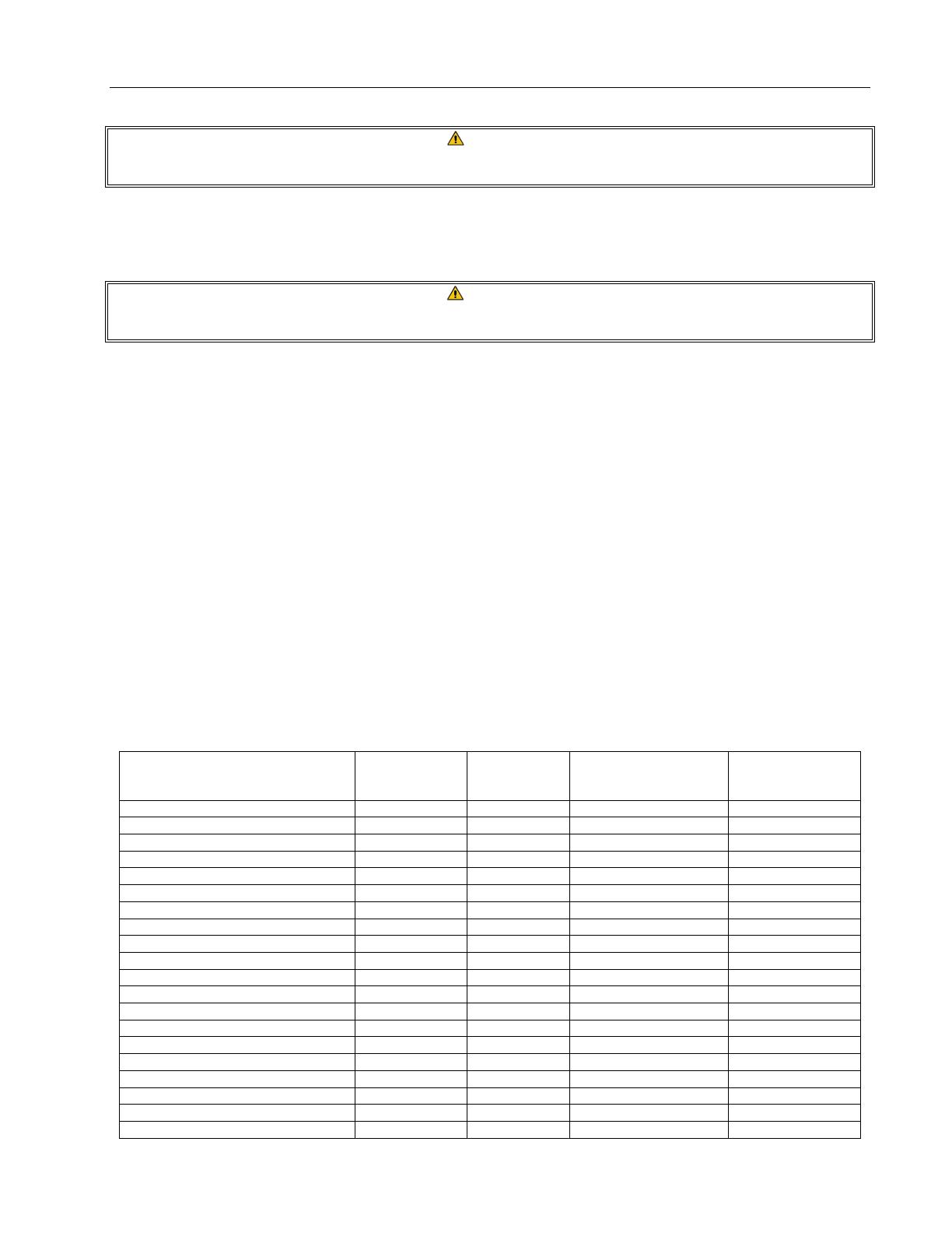
2.4 Recommended Spare Parts
DESCRIPTION
PART #
SR42- NON-
CE
PART #
SR42- CE
PART #
SR52/SR62- NON-CE
PART #
SR52/SR62- CE
Operating Thermostat 807-3515 807-1692 807-3515 807-1692
High-Limit Thermostat 807-3516 807-3560 807-3680 807-3560
Thermopile 810-2033 807-3565 810-2033 807-3565
Thermocouple N/A 812-1284 N/A 812-1284
Pilot Burner, Natural Gas 810-2032 810-2032 810-2032 810-2032
Pilot Burner, Propane Gas 810-2155 810-2155 810-2155 810-2155
Pilot Bracket, AGA N/A 200-6564 N/A 200-6564
Pilot Thermopile Bracket N/A 810-2401 N/A 810-2401
Piezo Ignitor Trigger N/A 810-1001 N/A 810-1001
Piezo Ignitor Bracket N/A 200-1868 N/A 200-1868
Piezo Ignitor Electrode N/A 807-3540 N/A 807-3540
Orifice, Natural 810-2040 810-2060 810-2048 810-2060
Orifice, Natural, units built after 4/07 810-3097 810-3101 N/A N/A
Orifice, Propane 810-2064 810-2059 810-2059 810-2059
Orifice, Propane, units built after 4/07 810-3099 810-3102 N/A N/A
Gas Valve, Natural 807-1603 807-2122 807-1603 807-2122
Gas Valve, Propane 807-1604 807-2121 807-1604 807-2121
Leg 810-2053 810-2053 810-2053 810-2053
Caster, 5-inch w/o Brake 810-0356 810-0356 810-0356 810-0356
Caster, 5-inch w/Brake 810-0357 810-0357 810-0357 810-0357
SUPER RUNNER SERIES GAS FRYERS
CHAPTER 2: OPERATION
2-4
2.5 Wiring Diagram
CE UNITS ONLY:
WARNING
DO NOT CONNECT ANY EXTERNAL
ELECTRICAL POWER TO THIS UNIT
THERMOPILE
HONEYWELL 807-3565
COAXIAL LEAD TO
THERMOCOUPLE 812-1284
HIGH-LIMIT
OPERATING
THERMOSTAT
HONEYWELL CE
PP
TH
PP
TH
NON-CE UNITS ONLY:
3
0
0
N/O
COM N/C
2
0
0
2
5
0
OFF
1C
4C
3C
HON EYWELL
1/2 P.S.I.
ON
HONEYWELL
PILOT
1/2 P.S.I.
PILO T
ADJ.
3
5
0
4
0
0
2C
C
HONEYWELL 1/2 P.S.I.
HIGH-LIMIT
OPERATING
THERMOSTAT
PILOT
GENERATOR
CONTROL CIRCUIT
THIS PAGE INTENTIONALLY LEFT BLANK
Dean, 8700 Line Avenue, PO Box 51000, Shreveport, Louisiana 71135-1000
Shipping Address: 8700 Line Avenue, Shreveport, Louisiana 71106
TEL 1-318-865-1711 FAX (Parts) 1-318-219-7140 FAX (Tech Support) 1-318-219-7135
Price: $10.00
PRINTED IN THE UNITED STATES
819-5999
MARCH 08
  • Page 1 1
  • Page 2 2
  • Page 3 3
  • Page 4 4
  • Page 5 5
  • Page 6 6
  • Page 7 7
  • Page 8 8
  • Page 9 9
  • Page 10 10
  • Page 11 11
  • Page 12 12
  • Page 13 13
  • Page 14 14

Dean SR42 User manual

Category
Deep fryers
Type
User manual

Ask a question and I''ll find the answer in the document

Finding information in a document is now easier with AI