Page is loading ...

XG0207 - 170223
Installation & Maintenance Manual
• Theinstallationofthisreplacemustbedonebya
qualiedandcertiedgasapplianceinstaller.
• Checklocalcodesandreadallinstructionspriorto
installation.
®
C
US
WARNING:
FIRE OR EXPLOSION HAZARD
Failure to follow safety warnings exactly could result in serious injury,
death, or property damage.
—Donotstoreorusegasolineorotherammablevaporsand
liquidsinthevicinityofthisoranyotherappliance.
— WHAT TO DO IF YOU SMELL GAS
• Do not try to light any appliance.
• Do not touch any electrical switch; do not use any
phoneinyourbuilding.
• Leavethebuildingimmediately.
• Immediatelycallyourgassupplierfromaneighbour's
phone. Follow the gas supplier’s instructions.
• Ifyoucannotreachyourgassupplier,callthere
department.
—Installationandservicemustbeperformedbyaqualied
installer,serviceagencyorthegastter.
H See-Through INDOOR GAS FIREPLACE
H38FSDN Natural Gas
H38FSDL Propane Gas
H38FSDNI Natural Gas
H38FSDLI Propane Gas
Read and understand this manual. Improper installation, adjustment,
alteration, service or maintenance can cause serious injury, property
damage or even death. For assistance or additional information
consult a qualied installer, service agency or the gas supplier.
A barrier designed to reduce the risk of burns from the
hot viewing glass is provided with this appliance and
shall be installed for the protection of children and other
at-risk individuals.
HOT GLASS WILL
CAUSE BURNS.
DO NOT TOUCH GLASS
UNTIL COOLED.
NEVER ALLOW CHILDREN
TO TOUCH GLASS.
Installation and service must be performed by a qualied installer,
service agency or the gas tter.
Installer: Leave this manual with the appliance.
Consumer: Retain this manual for suture reference.
NOTICE
CAUTION
DANGER
DANGER
H42FSDN Natural Gas
H42FSDL Propane Gas
H42FSDNI Natural Gas
H42FSDLI Propane Gas
Some materials used in the manufacturing process of this product can
expose you to Benzene which is known in the State of California to
cause cancer and birth defects or other reproductive harm. For more
information go to www.P65warnings.ca.gov
WARNING

XG0207 - 1702232
General
Congratulations on your purchase of a Montigo Fireplace.
With over 30 years of experience, Montigo is committed to providing
you with a gas fireplace that is not only a beautiful addition to your
space, but that is also designed and manufactured to the highest
safety, reliability and engineering standards.
We strongly encourage you to read and carefully follow the
instructions laid out in this Installation, Operation and Maintenance
Manual and retain it for your future reference. Pay special attention
to all cautions, warnings, and notices throughout this manual
intended to ensure your safety.
This manual covers installation, operation and maintenance. Lighting,
operation and care of this replace can be easily performed by the
homeowner. All installation and service work should be performed
by a qualied or licensed installer, plumber or gas tter as certied
by the state, province, region or governing body where the replace
is being installed.
This installation, operation and maintenance manual is applicable
to the models described in Table 1. Refer to your rating plate to
verify included options.
Warranty and Installation Information: (See Appendix B)
The Montigo warranty will be voided by, and Montigo disclaims any
responsibility for, the following actions:
• Modication of the replace and/or components including Direct-
Vent assembly or glass doors.
• Use of any component part not manufactured or approved by
Montigo in combination with this Montigo replace system.
• Installation other than as instructed in this manual.
• Consult your local Gas Inspection Branch on installation
requirements for factory-built gas replaces. Installation & repairs
should be done by a qualied contractor.
Introduction
Safety Alert Key
Indicates a hazardous situation which, if
not avoided, WILL result in death or serious
injury or property damage.
Indicates a hazardous situation which, if not
avoided, WILL result in minor or moderate
injury.
Indicates a hazardous situation which, if not
avoided, COULD result in death or serious
injury or property damage.
Indicates practices that are important, but
not related to personal injury.
DANGER
CAUTION
WARNING
NOTICE
Figure 1 H38ST, H42ST, Specications
MODEL
Natural Gas
Propane
Gas Rating (BTU hr)
Traditional Burner /Logset
Standing Pilot Ignition
SIT Electronic Ignition
H38DFSTN X 34,000 X X
H38DFSTL X 34,000 X X
H38DFSTNI X 34,000 X X
H38DFSTLI X 34,000 X X
H42DFSTN X 37,000 X X
H42DFSTL X 37,000 X X
H42DFSTNI X 37,000 X X
H42DFSTLI X 37,000 X X

XG0207 - 170223 3
General
Contents
Safety Alert Key ....................................................................................................................... 2
Introduction ............................................................................................................................ 2
Section A: Before You Begin .................................................................................................... 4
Installation Checklist ................................................................................................................. 4
Standard Installation Checklist ................................................................................................ 5
Rating Plate Sample .................................................................................................................. 6
Section 1: Product Dimensions .............................................................................................. 7
P/PL 38 and 42 Dimensions ..................................................................................................... 7
P/PL 52 Dimensions .................................................................................................................. 8
Section 2: Framing .................................................................................................................. 9
Clearances: ............................................................................................................................... 11
Installing The Standoffs ..........................................................................................................11
Installing the Nailing Flange Extension ................................................................................. 11
Section 3: Venting ................................................................................................................. 12
Section3-2:InstallingaRoofMountedDirectVentTerminationfor5''/8''(PVTK1SS) 13
Section 3-2-1: Venting Layout ................................................................................................13
5"/ 8" Piping for P52 and PL52 units .....................................................................................14
Section3-3:InstallingaWallMountedTermination5''/8'' .............................................. 15
InstallingaWallMountedTermination5''/10'' ................................................................. 16
Section 3-3-1: Venting Layout: Wall Mounted Termination ............................................. 17
Top Venting Graph P38, PL38: ...............................................................................................17
Rear Venting Graph P38, PL38: .............................................................................................. 18
Top Venting Graph P42, PL42: ...............................................................................................19
Rear Venting Graph P42, PL42: .............................................................................................. 20
Top Venting Graph (5''/8'') P52, PL52: ...................................................................................21
Top Venting Graph (5''/10'') P52, PL52: ................................................................................. 22
45° Corner Installation 5''/8'': .................................................................................................23
45° Corner Installation 5''/10'': ...............................................................................................23
45° or less Corner Installation 5''/8'': ....................................................................................23
45° or less Corner Installation 5''/10'': ..................................................................................23
Section 3-3-2: Venting Components ......................................................................................24
Section 3-3-2.2: Simpson Duravent Venting Components .................................................25
Section 3-3-2.3: ICC Venting Components* ..........................................................................26
Section 3-3-2.4: Metalfab Venting Components* ................................................................ 26
Section3-3-3:HeatShields5''/8'' ......................................................................................... 27
HeatShields5''/10''(ForP52DFandPL52DF) ..................................................................... 28
Section 4: Wiring ................................................................................................................... 29
Installation of Electrical Supply .............................................................................................. 29
Installation of the wall switch.................................................................................................30
CPI[ContinuousPilotIgnition]/IPI[IntermittentPilotIgnition]JumperCable
Installation .............................................................................................................................31
“Why use CPI mode”? .............................................................................................................. 31
The difference between IPI and CPI: ..................................................................................... 31
Installing the CPI Jumper Cable ............................................................................................. 31
Section 5: Installing the gas line...........................................................................................32
Fuel Type .................................................................................................................................. 32
Gas Pressure ............................................................................................................................ 32
Section 5-3: GAS CONNECTION ............................................................................................. 32
Section 6: Finishing ................................................................................................................33
Finishing Around the Fireplace .............................................................................................. 33
Mantels & Surrounds .............................................................................................................. 34
Section7:ScreenInstallationandRemoval .......................................................................35
Removing the Screen .............................................................................................................. 35
To Install Screens: .................................................................................................................... 35
Replacement Screens:............................................................................................................. 35
Section8:Installing&RemovingtheDoor .........................................................................36
Removing the door: ................................................................................................................. 36
Reinstalling the door ............................................................................................................... 36
Section 9: Installing the Accessories ....................................................................................37
Installing the Uplighting Glass ............................................................................................... 37
Installing the Firestones or optional Fireglass .................................................................... 37
Installing Optional Speckled Stones ..................................................................................... 37
Optional Log Set ...................................................................................................................... 38
Log Kit Installation ................................................................................................................... 38
Remote Operation (Optional for PL Units) .........................................................................41
Section10:CleaningandMaintenance ..............................................................................45
General ..................................................................................................................................... 45
Cleaning .................................................................................................................................... 45
Replacing Light Bulbs .............................................................................................................. 46
Troubleshooting ...................................................................................................................... 46
Replacement Parts ................................................................................................................47
Appendix A: Venting Terminations ...................................................................................... 48
Appendix B: Warranty ...........................................................................................................49
Appendix C: Amendment
(GasFireplace/EquipmentsoldintheStateofMassachusetts) ..................................... 50

XG0207 - 1702234
General
IMPORTANT MESSAGE: SAVE THESE INSTRUCTIONS
The H See Through replaces must be installed in accordance with
these instructions. Carefully read all the instructions in this manual
rst. Consult the Local Gas Branch to determine the need for a permit
prior to starting the installation. It is the responsibility of the installer to
ensure this replace is installed in compliance with the manufacturers
instructions and all applicable codes.
Installation Checklist
• Determine the desired install location of your replace.
• See Section 1, Dimensions and refer to the Framing Section 2 for
details.
• Select the location of your termination and resulting vent run.
• Your selected termination location must be the highest point in the
Direct Vent installation.
• Should it be impossible to meet the venting requirements laid out in
Section 3: Venting, please contact a local Montigo dealer regarding
the use of a Montigo Power Vent.
• Lay out the Vent run; calculating the required elbows and straight
runs of 5"/8" ex and/or rigid pipe.
• Layout Electrical Requirements Refer to Section 4: Wiring, for Details.
• Refer to Section 5: Installing the Gas Line, for details on the gas
connection and access.
• Refer to local codes and guidelines for installation requirements.
• Installation and repairs should be done by a qualied contractor
and must conform to:
• Installations in Canada must conform to the local codes or in
the absence of local codes to the current version of Natural Gas
and Propane Installation Code, CSA B149. Electrical installations
must conform to the local codes or, in the absence of local codes,
to the current version of Canadian Electrical Code, CSA C22.1.1
• Installations in the USA must conform to the local codes or in
the absence of local codes to the current version of National
Fuel Gas Code, ANSI Z223.1/NFPA 54. Electrical installations
must conform to the local codes or, in the absence of local
codes, to the current version of the National Electrical Code,
ANSI/NFPA 70. See Appendix C for installation within the State
of Massachusetts
Do not use this appliance if any part has been under water.
Immediately call a qualied service technician to inspect the appliance
and to replace any part of the control system and any gas control that
has been under water
Due to high temperatures, the appliance should be located out of
trac and away from furniture and draperies
Children and adults should be alerted to the hazards of high surface
temperature and should stay away to avoid burns or clothing ignition
A barrier designed to reduce the risk of burns from the hot viewing
glass is provided with this appliance and shall be installed for the
protection of children and other at-risk individuals
Clothing or other ammable material should not be placed on or near
the appliance
Installation and repair should be done by a qualied service person.
The appliance should be inspected before use and at least annually
by a professional service person. More frequent cleaning might be
required due to excessive lint from carpeting, bedding material, etc. It
is imperative that control compartments, burners, and circulating air
passageways of the appliance be kept clean
NOTICE
NOTICE
NOTICE
NOTICE
NOTICE
NOTICE
Section A: Before You Begin

XG0207 - 170223 5
General
Standard Installation Checklist
This standard installation checklist is to be used by the installer in conjunction with, not instead of, the instructions contained within this
installation manual.
Customer Date Installed:
Install Address: Location of Fireplace:
Installer:
Model (circle one): H38DFSTN, H38DFSTL, H38DFSTNI, H38DFSTLI
H42DFSTN, H42DFSTL, H42DFSTNI, H42DFSTLI
Dealer Phone:
Serial #:
*Only applicable for PL Series
YES NO IF NO, WHY NOT?
Appliance Install: Section 2
Framing complies with install manual.
Standos have been installed.
Proper clearances have been maintained.
Venting: Section 3
Venting conguration complies with vent diagrams.
Venting installed, fastened, and secured in place maintaining proper clearance.
Firestops installed.
Exterior wall/roof ashing installed and sealed in compliance with local building code.
Terminations installed and sealed in compliance with local building code.
Direct vent termination is highest point in vent assembly.
Wiring/Electrical:Section4
Unswitched power provided to the appliance PPO box.
Low voltage wire connected to dry contact wall switch (non-powered)*
Gas: Section 5
Proper appliance for fuel type.
Was a conversion performed?
Leak check performed & inlet pressure veried.
Finishing: Section 6
Only non-combustible materials installed in non-combustible areas.
Clearances meet installation manual requirements
Mantels and/or projections comply with install manual
Appliance Setup: Section 7 through 9
Media, door, and screen installed according to install manual
Manual given to home owner.
Started appliance and veried no gas leaks exist.
Comments:

XG0207 - 1702236
General
Rating Plate Sample
Figure 1.1 Rating Plate for standing pilot (SIT) Figure 1.2 Rating Plate for IPI electronic ignition
LBL1205-V6.1 Stand. Pilot- Screen DEC06.2014
Teklynx LabelView Demo
LB1223-V5.1 SIT IPI -with screen DEC06.2014
Teklynx LabelView Demo

XG0207 - 170223 7
General
H38DFSTDimentions
H42DFST Dimentions
Figure 2. Fireplace dimensions (Tolerance ± ⅛").
Figure 2. Fireplace dimensions (Tolerance ± ⅛").
Section 1: Product Dimensions
Please review the Installation Checklist for general information on
preparing for a successful installation of your replace.
The replace may be installed in any location that maintains proper
clearances to air conditioning ducts, electrical wiring and plumbing.
Safety, as well as eciency of operation, should be considered when
selecting the replace location. Select a location that does not interfere
with room trac, has adequate ventilation and oers an accessible
path for Direct Vent installation.
998
39
5
16
"
669
26
3
8
"
895
35
1
4
"
132
5
3
16
"
947
37
5
16
"
187
7
3
8
"
76
3"
218
8
5
8
"
853
33
9
16
"
92
3
5
8
"
GAS
SUPPLY
POWER
SUPPLY
1101
43
5
16
"
640
25
3
16
"
927
36
1
2
"
1030
40
9
16
"
175
6
7
8
"
927
36
1
2
"
127
5"
203
8"
959
37
3
4
"
305
12"
610
24"
HS38DF-ST
DIMENSIONS TOLERANCES ARE IN:
METRIC - MM
1.6 MM
IMPERIAL - FRACTIONAL
1/16"
THE INFORMATION CONTAINED IN THIS DRAWING IS THE SOLE PROPERTY OF CANADIAN HEATING PRODUCTS. ANY REPRODUCTION IN PART OR AS A WHOLE WITHOUT THE WRITTEN PERMISSION OF CANADIAN HEATING PRODUCTS IS PROHIBITED.
PROPRIETARY AND CONFIDENTIAL
December 5, 2017
DATE:
134
5
1
4
"
772
30
3
8
"
1000
39
3
8
"
1106
43
9
16
"
1049
41
5
16
"
1036
40
13
16
"
949
37
3
8
"
77
3"
187
7
3
8
"
218
8
5
8
"
93
3
5
8
"
GAS
SUPPLY
POWER
SUPPLY
640
25
3
16
"
1029
40
1
2
"
1193
46
15
16
"
1128
44
3
8
"
1067
42"
127
5"
203
8"
610
24"
305
12"
175
6
7
8
"
H42DF-ST
DIMENSIONS TOLERANCES ARE IN:
METRIC - MM
1.6 MM
IMPERIAL - FRACTIONAL
1/16"
THE INFORMATION CONTAINED IN THIS DRAWING IS THE SOLE PROPERTY OF CANADIAN HEATING PRODUCTS. ANY REPRODUCTION IN PART OR AS A WHOLE WITHOUT THE WRITTEN PERMISSION OF CANADIAN HEATING PRODUCTS IS PROHIBITED.
PROPRIETARY AND CONFIDENTIAL
December 8, 2017
DATE:

8
Installation
XG0207 - 170223
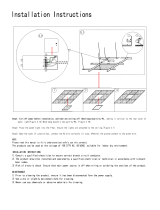
NOTE: When constructing the framed opening, please ensure there is
access to install the gas line when the unit is installed
• Slide the replace into the cavity.
• Tack four studs (Vertical, "broken line") in place, shown
• Secure the replace in position by nailing into these cleats.
Section 2: Framing
Figure 3. Framing dimensions, (Both Sides Typical)
When this appliance is installed directly on ANY combustible other
than wood ooring (carpet, vinyl, etc.). It must be installed on an
equivalent wood or metal panel. This material must extend the full
width and depth of the appliance.
WARNING
In wall framing dimensions Shelfoverthefireplace,Topvent
Shelfoverthefireplace,Sidevent
Alcoveabovefireplace
Figure 3.b Combustible Framing for shelves over the replace, Top vent.
Figure 3.b Combustible Framing for shelves over the replace, Side vent.
Figure 3.b Non Combustible Framing with alcove above replace, Right side. Combustible
Framing above replace, Left side, see gure 2. (Top Vent).
A B C D E
H38DFST 40¾'' 42½'' N/A 23¾'' 40¾''
H42DFST 45'' 49½'' 46½'' 24'' 45''
1" Min.
Non-combustiblenailing
ange(supplied)Both
sides typical
Non-combustible
materials.Alcove
overreplace
CeilingLevel
Door
Opening
Floor
H42STNon-Combustible
header (Supplied)
NOTNEEDEDFORH38ST
Both walls typical. May not
beexactlyasshown
NON-COMBUSTIBLE HEADER (H42ST ONLY)
COMBUSTIBLE HEADER
COMBUSTIBLE
MATERIAL
BACKFRAME
Combustiblematerial
backframe,2-peices.Both
sides typical
Non-Combustible
header
Combustible
header
A
B
C
D
E
F
J
G
L
M
O
P
N Q
K
H I
H38DFST
H42DFST
F 46'' 50''
G 17½'' 19''
H N/A 46½''
I 42½'' 49½''
H38DFST
H42DFST
J 33½'' 37⅜''
K N/A 46½''
L 42½'' 49½''
M 10'' 11½''
H38DFST
H42DFST
N 42½'' 49½''
O 6'' 6''
P 10'' 10''
Q 36½'' 40½''
NON-COMBUSTIBLE HEADER (H42ST ONLY)

9
Installation
XG0207 - 170223
ClearancesH38DF*ST
ClearancesH42DF*ST
Installing the Nailing Flange Extension
MODEL
Top - Side
vent†
Top - Top
vent†
Sides
Floor
Mantel
H*38DF*-ST 10" 17½" 2" 0"
See Section 6
Finishing around the
replace
H*42DF*-ST 12" 19" 2" 0"
Figure 4. Combustible Wall Clearances
When installing a shelf over the top of the replaces, the following
guidelines must be adhered to:
For Side Vent applications, the minimum clearance is 2" from the side of
the replace to a wall, or any combustible materials, and 10" clearance
from the top of the replace to the underside of any combustible shelf
materials.
For Top Vent applications, the minimum clearance is 2" from the side
of the replace to a wall, or any combustible materials, and 17 1/2" to
the underside of any combustible shelf materials.
1” clearance is maintained on sides and bottom of vent runs and 2”
above horizontal vent runs to any combustible material.
When installing a shelf over the top of the replaces, the following
guidelines must be adhered to:
For Side Vent applications, the minimum clearance is 2" from the Side
of the replace to a wall and 12" clearance from the top of the replace
to the underside of any combustible shelf materials.
For Top Vent applications, the minimum clearance is 2" from the Side
of the replace to a wall and 19" to the underside of any combustible
shelf materials.
1” clearance is maintained on sides and bottom of vent runs and 2”
above horizontal vent runs to any combustible material.
† Note: Clearance from top of replace to a ceiling within the replace
enclosure.
** Note: For mantel clearance, please refer to Section 6: Finishing
Once the replace is placed into the rough framed opening, the supplied
Nailing Flange Extension (Part No. H42074) must be fasten securely
into place, with nails or wood screws.
Note: The nailing ange extension can be substituted with a
pieceofNON-Combustiblematerialofthesamesizeandthermal
characteristics,ie:cementboardorequivalent.Thisisrecommended
inapplications wherethe facingmaterials will notadhere tothe
metalnailingange.
The Supplied nailing extension must be placed along the top edge of
the replace and securely fastened in place to the non combustible
header and combustible wood framing.
Figure 4.b Installing standos

10
Installation
XG0207 - 170223
Figure 5. Flue cover and collar removal, Top Vented replace.
Figure 5.b Flue cover and collar installation, Side Vented replace.
Section 3: Venting
Montigo supplies a variety of direct venting and termination options.
The direct vent termination location MUST be selected such that it is the
highest point in the venting assembly. It should also be selected such
that it provides the shortest vent run possible. Should it be impossible
to ensure that the termination is the highest point or to meet the
venting guidelines laid out below please contact your Montigo dealer
to discuss power venting options.
Notes For Planning Venting:
• Venting can originate from the unit through the top or through the rear
• Venting can terminate through the roof or through an exterior wall.
• Refer to Appendix A - Termination Locations to ensure the planned
termination location is acceptable.
• Once the termination location has been established, refer to the
appropriate section below for installation details
• All replaces shipped from the factory are top vent.
• Silicone application is NOT required when joining Montigo vent
pipes and components.
Section3-1:ConvertingtoSideVent
Use the following instructions to convert a unit for side vent use:
• Remove the Side ue cover and gasket (5" and 8") on the ue outlet,
as shown in Figure 5.
• Next, Remove the Top ue collar's (5" and 8") on the ue outlet, as
shown in Figure 5.
• Install the (removed) Side ue cover and gasket material, to the Top
vent outlet. Fasten the cover with included hardware, as illustrated
Figure 5b.
• Install the (5" and 8") collars to the Side vent outlet using the included
hardware, as illustrated Figure 5b.
Outer Flue
Plate
5" Inner Flue
Cover Plate
5" Inner Flue
Cover Plate
5" Inner Flue
Collar
8" Outer Flue
Collar
8" Outer Flue
Collar
8" Outer Flue
Cover Plate
Flue Collar
Under no circumstances can Montigo ex venting be cut to
accommodate an installation. Use an alternative length to complete
your vent run.
NOTICE

11
Installation
XG0207 - 170223
Roof mounted terminations
The following details are some possible congurations for roof mounted
terminations. See below.
This section applies to installations where the direct vent termination
will be roof mounted.
Section 3-2-1: Venting Layout
Selection of components and details of venting lay out should adhere
to the following guidelines:
• The maximum termination point is 32’ above the replace (NOTE:
if the maximum termination height is used, the ame pattern may
be aected).
• The Vertical termination must be a minimum 2’ higher than where
the termination exits the roong materials, (asphalt shingles, cedar
shakes, etc). This distance should be measured from the high side of
the roof slope where the ue ashing intersects the roong materials.
(see Figures 8 to 8c).
• Termination location must be a minimum 6’ from a mechanical air inlet.
• Termination location must be a minimum 18” from a parapet wall.
• For a more detailed diagram of allowed termination locations, see
Appendix A.
• A maximum of two osets (each oset is made up of 2-90° bends)
may be made for vertical vent runs.
• Firestops must be installed as required by National & local codes.
• Ensure all horizontal runs are supported with a minimum of 3
supports per 10’ of venting.
• Install all roof ashing and storm collars as shown.
Figure 6. Top vent, roof mounted termination with no oset in vent run.
Figure 6.b Top vent, Roof mounted with 1 oset (1 oset= two 90° bends).
Figure 6.c Top vent, Roof mounted with 2 osets (1 oset= two 90° bends).
Section 3-2: Installing a Roof Mounted Direct Vent
Termination
PVTK1 Termination
PVTK1 Termination
PVTK1 Termination
Storm collar
Storm collar
Storm collar
2' min
2' min
2' min
Support ring
Support ring
Support straps OR
Support ring and plates
Support ring and plates
Support plate
Support plate
Firestop
Firestop
Firestop
Firestop
Firestop
32' max
32' max
32' max
Roof ashing
PEXT
PEXT-10
Adaptor
Flue
Collar
Roof ashing
Roof ashing

12
Installation
XG0207 - 170223
Figure 6.d Side vent, Roof mounted venting (1 = 90° bend).
Storm collar
Support plate
32' max
Roof ashing
MVTK1 Termination
Support ring
PEXT Solid Sections
2' min.
12"
max.
Firestop
Firestop
90° Elbow

13
Installation
XG0207 - 170223
Figure 7. Installing a PTO4-F termination.
Figure 7.b Installing a PTO termination with the MSR frame.
Figure 7.c Installing a PTO termination with the BSR frame.
Figure 7.d Installing a PTO termination with MOSR frame.
Figure 7.e Installing the VSS Vinyl Shield.
Figure 7.f Installing a PTO termination heat guard.
1
12”
2”
1
2”
12”
This section applies to installations where the direct vent termination
will be wall mounted. NOTE: If subject to a highly corrosive environment
i.e. Seaside, Montigo recommends using Stainless Steel Termination.
Section3-3:InstallingaWallMountedTermination5''/8''
Installationofterminationwithbuiltinframe
A termination with a built-in frame is installed during framing of a
structure.
1. Frame the termination opening to 11" x 11".
2. Install exterior sheathing to the structure framing.
3. Fasten the termination to the sheathing using a minimum of 4 screws.
MSR Frame
PTO-4 (5"/8")
Termination
PTO-4F (5"/8")
Termination
Installationofaterminationshieldforvinylsiding
The VSS Termination shield is installed when the exterior of a structure
is clad with Vinyl siding. It is placed directly above, and on-center with
the termination.
Installation of termination frame at time of framing
Terminations with a MSR frame allow the installation of the frame prior
to installation of the termination.
1. Frame the termination opening to 12" x 12".
2. Secure the MSR Frame to the exterior sheathing of the structure.
3. Fasten the termination to the MSR Frame using a minimum of 4 screws.
1. Frame the MOSR opening to 12" x 12".
2. Fasten the MOSR frame to the interior side of the studs, concrete,
or nished wall construction using a minimum of 4 screws.
3. Insert the termination into the MOSR frame as shown here, (from
the inside) and attach to the MOSR by installing a min. quantity of 4
bolts into the threaded nuts on the MOSR Frame.
Installation of termination frame at time of framing in masonry
Terminations with a BSR frame allow the installation of the frame in
masonry prior to the installation of the termination
1. Frame the BSR opening to 12" x 12".
2. Secure the BSR Frame to the exterior sheathing of the structure.
3. Fasten the termination to the BSR Frame using a minimum of 4 screws.
BSR Frame
MTKOG 5"/8")
Installing heat guards
Installing heat guards over terminations is recommended in installations
where the termination is located within 7' feet above grade, or above
a pedestrian walkway, and may be required by code in public areas.
1. Ensure that the two long mounting brackets are facing the bottom
of the termination (See inset). This will provide more heat protection
at the top of the termination, where temperatures are highest.
2. Attach to the faceplate of the termination using four sheet metal
screws.
1
1”
11”
Framing
Exterior
Sheathing
Fastening Hard-
ware, minimum
4-screws
Framing
Exterior
Sheathing
Fastening Hardware,
minimum 4-screws
PTO-4 (5"/8")
Termination
Framing
Exterior
Sheathing
Fastening Hardware,
minimum 4-screws
Exterior Vinyl
siding
PTO-4 (5"/8")
Termination
VSS Vinyl shield
Installation of termination from inside structure
A Termination with a MOSR Frame is installed from the inside of the
structure. These are commonly used in high-rise construction.
MOSR Frame
PTO-4 (5"/8")
Termination
12”
12”
Fastening Hardware,
minimum 4-screws
Framing,
concrete
or other
materials
Exterior
Sheathing, concrete
or other materials

14
Installation
XG0207 - 170223
Figure 8.b H38DFST Top Vent Venting Graph for wall mounted terminations
Figure 8. Top Vented, wall mounted installation with 1 elbow (1 one 90° bend). The vent run
must comply with Venting Graph for Top vent, wall mounted terminations
Figure 8. Top Vented, wall mounted Multi-elbow installation. See Venting Graph for Top vent,
wall mounted terminations
Figure 8. Top Vented, wall mounted Retracted Multi-elbow installation
Selection of components and details of venting layout should adhere
to the following guidelines:
• Vent terminations must not be recessed in walls or siding.
• For Heat Shield requirements see Section 3-3.
• Once the proposed venting layout has been determined refer to
graph to ensure the layout is acceptable.
Notes Wall Mounted Terminations: TOP VENT
• All measurements for vertical or horizontal runs are measured from
center of the vent pipe.
• Venting runs must fall within the limits set by the venting graph.
Top Venting Graph
Measure the vertical height from the replace hearth to the centre of
the termination and the horizontal run from the replace ue collar to
the wall ange of the termination. Plot on the Venting Graph with an 'X'.
If the 'X' falls on or above the top boundary of the shaded area, the
installation is acceptable.
H38DFSTTOPVENTRUN
ExampleA:(AcceptableInstallation)
If the vertical dimension from the hearth is 114" and the horizontal
run to the wall ange of the vent termination is 168", this would be an
acceptable installation.
ExampleB:(UnacceptableInstallation)
If the vertical dimension from the hearth is 36" and the horizontal run
to the wall ange of the vent termination is 84", this would not be an
acceptable installation.
ExampleC:(UnacceptableInstallation)
If the vertical dimension from the oor of the replace is 60" and the
horizontal run to the wall ange of the vent termination is 144", this
would not be an acceptable installation.
0
HEARTH
12
12
0
60
36
84
120
24
72
108
48
96
132
Vertical Height (In.)
Horizontal Run (In.)
36 60 84 108 132 15624 48 72 96 120 144 168 180
Acceptableventrun
within non-shaded area.
Unacceptableventrun
within shaded area.
A
B
C
Section3-3-1:H38STVentingLayout:WallMountedTermination
Exterior
Wall
Exterior
Wall
Exterior
Wall
46''
42''
Hearth
Termination
Heat Shield
46''
Min.
46''
Min.
46''
Min.
Rigid
Section
Rigid
Section
Flex
Section
Flex
Section
42''
Max.
15'
Max.
126" Max.
30" Max.
Termination
Termination
Heat Shield
Heat Shield

15
Installation
XG0207 - 170223
Figure 8. Straight run, Side Vented, wall mounted termination for H*38DF*-ST
Figure 8. Side Vented, wall mounted Multi-elbow termination installation. Installation for
H*38DF*-ST must have a minimum vertical rise of 48"
Figure 8. Side Vented, wall mounted Multi-elbow installation
Selection of components and details of venting layout should adhere
to the following guidelines:
• Vent terminations must not be recessed in walls or siding.
• For Heat Shield requirements see Section 3-3.
• Once the proposed venting layout has been determined refer to
graph to ensure the layout is acceptable.
Notes Wall Mounted Terminations: SIDE VENT
• All measurements for vertical or horizontal runs are measured from
center of the vent pipe.
• Venting runs must fall within the limits set by the venting graph.
ExampleA:(AcceptableInstallation)
If the vertical dimension from the hearth is 120" and the horizontal
run to the wall ange of the vent termination is 138", this would be an
acceptable installation.
ExampleB:(UnacceptableInstallation)
If the vertical dimension from the hearth is 48" and the horizontal run
to the wall ange of the vent termination is 96", this would not be an
acceptable installation.
ExampleC:(UnacceptableInstallation)
If the vertical dimension from the oor of the replace is 72" and the
horizontal run to the wall ange of the vent termination is 120", this
would not be an acceptable installation.
Side Venting Graph
Measure the vertical height from the replace hearth to the centre of
the termination and the horizontal run from the replace ue collar to
the wall ange of the termination. Plot on the Venting Grap with an 'X'.
If the 'X' falls on or above the top boundary of the shaded area, the
installation is acceptable.
H38DFSTSIDEVENTRUN
Figure 9. H38DFST Side Vent Venting Graph for wall mounted terminations
0
HEARTH
12
12
0
60
36
84
120
24
72
108
48
96
132
Vertical Height (In.)
Horizontal Run (In.)
36 60 84 108 132 15624 48 72 96 120 144 168 180
Acceptableventrun
within non-shaded area.
Unacceptableventrun
within shaded area.
A
B
C
Exterior
Wall
Hearth
Hearth
Termination
Flex or Rigid
Heat Sheild
Heat Sheild
PXT Extention
33
½
''
12''
48''
42''
32½''
Max.
48''
Max.
14½''
Min.
33½''
12''
Max.
30''
Max.
192'' Max.
12'' Max. horozontal
run with no vertical lift
Termination
Rigid
Section
Flex
Section

16
Installation
XG0207 - 170223
Figure 8.b H42DFST Top Vent Venting Graph for wall mounted terminations
Figure 8. Top Vented, wall mounted installation with 1 elbow (1 one 90° bend). The vent run
must comply with Venting Graph for Top vent, wall mounted terminations
Figure 8. Top Vented, wall mounted Multi-elbow installation. See Venting Graph for Top vent,
wall mounted terminations
Figure 8. Top Vented, wall mounted Retracted Multi-elbow installation
Selection of components and details of venting layout should adhere
to the following guidelines:
• Vent terminations must not be recessed in walls or siding.
• For Heat Shield requirements see Section 3-3.
• Once the proposed venting layout has been determined refer to
graph to ensure the layout is acceptable.
Notes Wall Mounted Terminations: TOP VENT
• All measurements for vertical or horizontal runs are measured from
center of the vent pipe.
• Venting runs must fall within the limits set by the venting graph.
Top Venting Graph
Measure the vertical height from the replace hearth to the centre of
the termination and the horizontal run from the replace ue collar to
the wall ange of the termination. Plot on the Venting Graph with an 'X'.
If the 'X' falls on or above the top boundary of the shaded area, the
installation is acceptable.
H42DFST TOP VENT RUN
ExampleA:(AcceptableInstallation)
If the vertical dimension from the hearth is 120" and the horizontal
run to the wall ange of the vent termination is 138", this would be an
acceptable installation.
ExampleB:(UnacceptableInstallation)
If the vertical dimension from the hearth is 48" and the horizontal run
to the wall ange of the vent termination is 96", this would not be an
acceptable installation.
ExampleC:(UnacceptableInstallation)
If the vertical dimension from the oor of the replace is 72" and the
horizontal run to the wall ange of the vent termination is 120", this
would not be an acceptable installation.
0
HEARTH
12
12
0
60
36
84
120
24
72
108
48
96
132
Vertical Height (In.)
Horizontal Run (In.)
36 60 84 108 132 15624 48 72 96 120 144 168 180
Acceptableventrun
within non-shaded area.
Unacceptableventrun
within shaded area.
A
B
C
Section 3-3-2: H42ST Venting Layout: Wall Mounted Termination
Exterior
Wall
Exterior
Wall
Exterior
Wall
50''
36''
NG
12''
LP
Hearth
Insulated
sleve
required
Termination
Heat Shield
50''
Rigid
Section
Rigid
Section
Flex
Section
Flex
Section
36'' Max. NG
12'' Max.
Propane
150"
Max.
126" Max.
30" Max.
Termination
Termination
Heat Shield
Heat Shield

17
Installation
XG0207 - 170223
Figure 8. Side Vented, wall mounted Multi-elbow termination installation. Installation for
H*42DF*-ST must have a minimum vertical rise of 48"
Selection of components and details of venting layout should adhere
to the following guidelines:
• Vent terminations must not be recessed in walls or siding.
• For Heat Shield requirements see Section 3-3.
• Once the proposed venting layout has been determined refer to
graph to ensure the layout is acceptable.
Notes Wall Mounted Terminations: SIDE VENT
• All measurements for vertical or horizontal runs are measured from
center of the vent pipe.
• Venting runs must fall within the limits set by the venting graph.
ExampleA:(AcceptableInstallation)
If the vertical dimension from the hearth is 120" and the horizontal
run to the wall ange of the vent termination is 138", this would be an
acceptable installation.
ExampleB:(UnacceptableInstallation)
If the vertical dimension from the hearth is 48" and the horizontal run
to the wall ange of the vent termination is 96", this would not be an
acceptable installation.
ExampleC:(UnacceptableInstallation)
If the vertical dimension from the oor of the replace is 72" and the
horizontal run to the wall ange of the vent termination is 120", this
would not be an acceptable installation.
Side Venting Graph
Measure the vertical height from the replace hearth to the centre of
the termination and the horizontal run from the replace ue collar to
the wall ange of the termination. Plot on the Venting Grap with an 'X'.
If the 'X' falls on or above the top boundary of the shaded area, the
installation is acceptable.
Hearth
Flex or Rigid
52''
Min.
14½''
Min.
37''
30''
Max.
H42DFST SIDE VENT RUN
Figure 9. H42DFST Side Vent Venting Graph for wall mounted terminations
0
HEARTH
12
12
0
60
36
84
120
24
72
108
48
96
132
Vertical Height (In.)
Horizontal Run (In.)
36 60 84 108 132 15624 48 72 96 120 144 168 180
Acceptableventrun
within non-shaded area.
Unacceptableventrun
within shaded area.
A
B
C
52''
42''

18
Installation
XG0207 - 170223
Connectionandinstallationofthevent
components should adhere to the following
guidelines:
Section 3-3-2: Venting Components
The following components and associated Montigo part numbers for
installation of a roof or wall mounted termination. Use of non-Montigo
approved parts will VOID the warranty and may impede operation of
the replace.
• Use any combination of rigid and ex pipe as required and in any
orientation (Male connectors can face in any direction).
• Flex sections may be stretched up to 50% of their total length (e.g.
a 24” section maybe stretched to 36”).
• Connect all vent sections using a minimum of three sheet metal
screws on the outer pipe ue.
• Ensure the pipe ends male to female slide in a minimum of 1 1/2”
of overlap.
• Ensure all horizontal runs are supported with a minimum of 3
supports per 10’ of venting.
• When hanging/supporting venting, ensure that 1” clearance is
maintained on sides and bottom of vent runs and 2” above horizontal
vent runs to any combustible material.
• Rigid pipe may be cut less than half way from the FEMALEENDONLY.
• Flex pipe cannot be cut
• Ensure when cutting sections of rigid pipe to maintain integrity of
internal supports.
• For ex venting, place the springs supplied with the pipe kit, between
the outer and inner pipes to keep the pipes separate and avoid any
possible hot spots.
• Montigo recommends the use of a ex section for the nal pipe
connected directly to the replace oering greater exibility of
installation and absorption of movement.
• Firestops must be installed as required by National & local codes.
IMPORTANT:
Please Refer to your Building Envelope Engineer
or Waterproong Consultant for a review of ALL
penetrations through exterior walls or the roof.
A - Termination PTO4 (3" Length)
PTO4F (3" Length)
PVTK1SS
B - Frame Kits MSR (Stucco Frame)
MOSR (Stucco Frame)
BSR-4 (4" Brick Frame)
BSR-6 (6" Brick Frame)
C - Flex Sections PFL - 1 (12" f/f Section)
PFL - 18 (18" f/f Section)
PFL - 2 (24" f/f Section)
PFL - 3 (36" f/f Section)
PFL - 4 (48" f/f Section)
PFL - 6 (72" f/f Section)
D - Rigid Pipe PEXT - 1 (12" f/m Section)
PEXT - 2 (24" f/m Section)
PEXT - 3 (36" f/m Section)
PEXT - 4 (48" f/m Section)
PEXT - 6 (72" f/m Section)
E - Rigid Pipe Extension PXT - 5 (5" f/f Section)
PXT - 12 (12" f/f Section)
PXT - 20 (20" f/f Section)
F-Elbows PEL-90MM (m/m 90º Elbow)
PEL-90FF ( f/f 90º Elbow)
PEL-90FM ( f/m 90º Elbow)
PEL-45FM ( f/m 45º Elbow)
G - Wall Penetration Kit PFVK01F
H-SupportRing&Plate PSPXT-8
I - Firestop FS-8
J-RoofFlashing PRF-7 (1/12 - 7/12 pt.)
PRF-12 (7/12 - 12/12 pt.)
K - Heat Shield RHS101
L - Heat Guard MTKOG

19
Installation
XG0207 - 170223
Section 3-3-2.2: Alternate Venting Components
The following components are approved for use with Montigo products. Please contact your local Montigo
dealer for further information.
Component
Montigo Part Number
Simpson Duravent
Part Number
ICC
Part Number
MetalFab
Part Number
Selkirk
Part Number
Termination PTO4 (3" Length)
PTO4F (3" Length)
PVTK1SS (5/8 Vent)
58DVA-HC (Horizontal 5/8 vent)
58DVA-VCH (Vertical 5/8 Vent)
Rigid Sections
(5/8Vent)
PEXT - 1 (12" f/m)
PEXT - 2 (24" f/m)
PEXT - 3 (36" f/m)
PEXT - 4 (48" f/m)
PEXT - 6 (72" f/m)
58DVA-06 (6")
58DVA-09 (9")
58DVA-12 (12")
58DVA-18 (18")
58DVA-24 (24")
58DVA-36 (36")
58DVA-48 (48")
58DVA-60 (60")
5DL6 (6")
5DL9 (9")
5DL1 (12")
5DL2 (24")
5DL3 (36")
5DL4 (48")
5D6 (6")
5D12 (12")
5D18 (18")
5D24 (24")
5D36 (36")
5D48 (48")
5DT-06
5DT-09
5DT-12
5DT-18
5DT-24
5DT-36
5DT-48
Rigid Pipe Extension PXT12 (12" f/f)
PXT20 (20" f/f)
58DVA-08A (12")
58DVA-16A (20")
5DLT (12")
5DLS1 (12")
5DLT2 (20")
5DSL2 (20")
5DAL (3" to 10")
5DT-AJ12 (12")
Rigid Telescopic Pipe 58DVA-17TA
58DVA-24TA
5DLA30
Elbows
(5/8Vent)
PEL-90MM (m/m 90º)
PEL-90FF ( f/f 90º)
PEL-90FM ( f/m 90º)
PEL-45FM ( f/m 45º)
58DVA-E30 (30°)
58DVA-E45 (45°)
58DVA-E60 (60°)
58DVA-E90 (90°)
5DE45 (45°)
5DE90 (90°)
5D45L (45°)
5D90L (90°)
5DT-EL45 (45°)
5DT-EL90 (90°)
SupportRing&Plate PSPXT-8 58DVA-DC 5CS 5DT-CS
Firestop FS-8 58DVA-WFS
58DVA-FS
5CS 5DFS 5DT-FS
Roof Flashing PRF-7 (1/12 - 7/12 pt.)
PRF-12 (7/12 - 12/12 pt.)
58DVA-FF (at roof)
58DVA-F6 (0/12 - 6/12 pt.)
58DVA-F12 (7/12 - 12/12 pt.)
5DF (0/12 - 6/12 pt.)
5DF-12 (7/12 - 12/12 pt.)
5DT-AF6
5DT-AF12
Metal/TileRoofFlashing 58DVA-F6DS (0/12-6/12 pt.)
58DVA-F12DS (7/12-12/12 pt.)
Heat Shield RHS101 58DVA-WTU
58DVA-WT
5WT
5WTE
5DT-WT
Attic Radiation Shield 58DVA-IS 5AS
5RDS
5DT-AIS
Vinyl Siding Heat Shield VSS
VSSSS
58DVA-VSK (Vinyl Siding Stando
Kit)
Wall Support 58DVA-WS 5WS 5DWS 5DTWSB
OsetSupport 58DVA-ES 5OS 5DT-OS
Vaulted Ceiling Support 58DVA-CS 5SS DRS 5DT-CCS
Storm Collar SC8 58DVA-SC 5SC
5SQSC
5DSC 5DT-SC
Montigo Fireplace Adapter 58DVA-AD-M1 TM-5AA6 5DNA
Montigo Termination Adapter 58DVA-AD-M2 TM-5TA1 5DMTA
* Must use Montigo termination, see section 3-3-2.
Montigo Direct vent units are also approved
for use with Flexmaster ex pipe.
FLEXMASTER

20
Installation
XG0207 - 170223
InstallingaWallMountedRHS8heatshield
The RHS8 Heat shield CANNOT be used WITHIN 36" horizontal or 60"
vertically of the replace, (see gure 18a). For applications within these
dimensions the RHS101 Heat Shield MUST be used.
To install the RHS8, frame an opening in combustible construction,
Figure 18 below. Slide the Heat shield in place over the vent pipe which
attaches to the replace. After the replace and vent pipe has been
installed, clearances should match the dimensions in Figure 18.
InstallingaWallMountedRHS101Heatshield
The RHS101 Heat shield MUST be used where the RHS8 Termination
(Figure 18 and 18a) CANNOT be used. Use the RHS100 within 36"
horizontal or 60" vertical.
To install the RHS101, Slide the Inner Section over the vent pipe that
will connect to the replace. Fasten the vent pipe to the back of the
replace with a Min. of three sheet metal screws.
Next, slide the RHS101 outer section from the outside of the structure.
To complete the installation fasten the Heat Shield Outer Section &
Termination frame to the structure.
Figure 15.e RHS101 Installation
Figure 15.c RHS101 Installation. (Install by sliding Outer Section over vent pipe where it passes
through the combustible construction.
Figure 15.a RHS8 Installation. (Install by sliding over vent pipe where it passes through the
combustible construction).
Figure 15.b RHS8 Installation. (Minimum requirements).
Figure 15.d Heat Shield. After sliding the outer section in place.
RHS8 Heat Shield
1” Min. Both sides Typical
1” Min.
1” Min.
Combustible Framing
Section3-3-3:HeatShields5''/8''
3/8'' min. Both sides Typical
Drywall / sheetrock
Drywall / sheetrock
RHS101 Heat Shield, inner Section
RHS101 Heat Shield, inner Section
Vent pipe, from replace
Vent pipe, from replace
Combustible framing
RHS101 Heat Shield Outer Section
RHS101 Heat Shield Outer Section
Termination
Termination
3/8'' min.
1'' min.
1'' min.
3/8'' min.
Inner shield
Outer shield
Combustible Framing
1'' min. Both sides Typical
RHS8 Heat Shield
Combustible framing
Exterior
Wall
Hearth
Termination
Heat Shield
60''
Min.
36''
Min.
/