Page is loading ...

MMM
I
MMMOPERATING INSTRUCTIONS
OPERATING INSTRUCTIONS
DUSTHUNTER SP100 Ex
Dust Concentration Monitor
Installation, Operation, Maintenance

2
8020016/ZS56/V2-1/2018-01| SICKOPERATING INSTRUCTIONS | DUSTHUNTER SP100 Ex
Subject to change without notice
Described Product
Product name: DUSTHUNTER SP100 Ex
Manufacturer
SICK Engineering GmbH
Bergener Ring 27 · D-01458 Ottendorf-Okrilla · Germany
Phone: +49 35205 524-10
Fax: +49 35205 524-50
E-Mail: info.pa@sick.de
Trademarks
Windows is a Microsoft Corporation trademark.
Other product names used in this document may also be trademarks and are only used
for identification purposes.
Legal Information
This document is protected by copyright. All rights derived from the copyright shall be
reserved for SICK Engineering GmbH. Reproduction of this document or parts of this
document is only permissible within the limits of the legal determination of Copyright
Law.
Any modification, shortening or translation of this document is prohibited without the
express written permission of SICK Engineering GmbH.
The trademarks stated in this document are the property of their respective owner.
© SICK Engineering GmbH. All rights reserved.
Original document
This document is an original document of SICK Engineering GmbH.

Contents
3
8020016/ZS56/V2-1/2018-01 | SICK O P E R A T I N G I N S T R U C T I O N S | DUSTHUNTER SP100 Ex
Subject to change without notice
1 Important information .............................................................................. 6
1.1 Main hazards...................................................................................................6
1.1.1 Hazard through hot and/or aggressive gases and high pressure 6
1.1.2 Hazards through electrical equipment .......................................... 6
1.1.3 Hazards through laser beam..........................................................6
1.1.4 Hazards through explosive or combustible gases, dust ...............6
1.2 Symbols and document conventions .............................................................7
1.2.1 Warning symbols ............................................................................7
1.2.2 Warning levels and signal words.................................................... 7
1.2.3 Information symbols .......................................................................7
1.3 Information on operation in potentially explosive atmospheres...................8
1.4 Intended use ...................................................................................................9
1.5 Responsibility of user....................................................................................10
1.5.1 General information......................................................................10
1.5.2 Safety information and protective measures ..............................10
2 Product description .................................................................................13
2.1 Measuring principle, measured variables....................................................13
2.1.1 Functional principle ......................................................................13
2.1.2 Response time ..............................................................................14
2.1.3 Function check..............................................................................15
2.2 Device components ......................................................................................17
2.2.1 Sender/receiver unit ....................................................................18
2.2.2 Flange with tube ...........................................................................20
2.2.3 Control unit MCU...........................................................................21
2.2.3.1 Standard interfaces ..................................................21
2.2.3.2 Versions .....................................................................22
2.2.3.3 Type code ..................................................................23
2.2.3.4 Modules.....................................................................24
2.2.4 Installation accessories................................................................25
2.2.5 Test equipment for linearity test..................................................25
2.3 Device configuration .....................................................................................26
2.3.1 Sender/receiver unit ....................................................................26
2.3.2 Voltage and purge gas supply ...................................................26
2.4 SOPAS ET (PC program) ................................................................................27
3 Assembly and installation ......................................................................28
3.1 Project planning ............................................................................................28
3.2 Assembly .......................................................................................................29
3.2.1 Fitting the flange with tube ..........................................................29
3.2.2 Fitting control unit MCU................................................................32
3.2.3 Fitting a weatherproof hood .......................................................33
Contents
Contents

Contents
4
8020016/ZS56/V2-1/2018-01 | SICKOPERATING INSTRUCTIONS | DUSTHUNTER SP100 Ex
Subject to change without notice
3.3 Electrical installation .................................................................................... 34
3.3.1 Electrical safety ............................................................................ 34
3.3.1.1 Properly installed power isolating switches............. 34
3.3.1.2 Lines with correct rating........................................... 34
3.3.1.3 Grounding the devices.............................................. 34
3.3.1.4 Potential equalization of explosion-protected
devices ...................................................................... 34
3.3.1.5 Responsibility for system safety .............................. 35
3.3.2 General information, prerequisites ............................................. 36
3.3.3 Installing the purge gas supply .................................................... 37
3.3.3.1 Purging with instrument air .................................. 37
3.3.4 Connecting control unit MCU ....................................................... 38
3.3.4.1 Work to be done ....................................................... 38
3.3.4.2 Connections for MCU processor board.................... 39
3.3.4.3 Connection of connection line to MCU .................... 40
3.3.4.4 Standard connection ................................................ 41
3.3.5 Connecting the MCU remote control unit.................................... 42
3.3.5.1 Connection to control unit MCU............................... 42
3.3.5.2 Connection to the MCU remote control unit............ 42
3.3.6 Fitting the interface and I/O module (option) ............................. 43
4 Commissioning and configuration........................................................ 44
4.1 Basics............................................................................................................ 44
4.1.1 General information ..................................................................... 44
4.1.2 Installing SOPAS ET ...................................................................... 44
4.1.2.1 Password for SOPAS ET menus................................ 44
4.1.3 Connection to the device via USB line ........................................ 44
4.1.3.1 Finding the DUSTHUNTER COM port........................ 45
4.1.4 Connection to the device via Ethernet (option) .......................... 46
4.2 Installing the sender/receiver unit .............................................................. 47
4.2.1 Adapting the sender/receiver unit to the flow direction............. 47
4.2.2 Fitting and connecting the sender/receiver unit ........................ 48
4.2.3 Assigning the sender/receiver unit to the measuring location
(in SOPAS ET)................................................................................ 49
4.3 Setting standard parameters ....................................................................... 51
4.3.1 Assigning the MCU to the sender/receiver unit.......................... 51
4.3.2 Factory settings ............................................................................ 52
4.3.3 Determining the function check .................................................. 53
4.3.4 Setting the analog outputs parameters ...................................... 54
4.3.5 Setting the analog inputs parameters......................................... 56
4.3.6 Setting the response time............................................................ 57
4.3.7 Calibration for dust concentration measurement ...................... 58
4.3.8 Data backup in SOPAS ET............................................................ 60
4.3.9 Starting measurement mode....................................................... 61

Contents
5
8020016/ZS56/V2-1/2018-01 | SICK O P E R A T I N G I N S T R U C T I O N S | DUSTHUNTER SP100 Ex
Subject to change without notice
4.4 Setting the Interface module parameters....................................................62
4.4.1 General information......................................................................62
4.4.2 Setting the Ethernet module parameters .................................63
4.5 Operating/setting parameters via the optional LC-Display.........................64
4.5.1 General information on use .........................................................64
4.5.2 Password and operating levels ....................................................64
4.5.3 Menu structure .............................................................................65
4.5.4 Parameter settings .......................................................................65
4.5.4.1 MCU ...........................................................................65
4.5.4.2 Sender/receiver unit.................................................68
4.5.5 Using SOPAS ET to modify display settings .................................69
5 Maintenance.............................................................................................71
5.1 General ..........................................................................................................71
5.2 Maintenance on the sender/receiver unit ..................................................73
5.2.1 Cleaning the optics of the sender/receiver unit..........................73
5.2.2 Checking the contamination value ..............................................74
5.2.3 Checking restricted breathing ......................................................75
5.3 Decommissioning..........................................................................................76
6 Troubleshooting .......................................................................................77
6.1 General ..........................................................................................................77
6.2 Sender/receiver unit.....................................................................................79
6.3 Control unit MCU ...........................................................................................80
6.3.1 Malfunctions .................................................................................80
6.3.2 Warning and malfunction messages in SOPAS ET......................80
6.3.3 Replacing the fuse........................................................................82
7 Specifications...........................................................................................83
7.1 Compliances..................................................................................................83
7.2 Technical data .............................................................................................84
7.3 Dimensions, Part Nos. ..................................................................................86
7.3.1 Sender/receiver unit ...................................................................86
7.3.2 Flange with tube ...........................................................................87
7.3.3 Control unit MCU...........................................................................88
7.3.4 Weatherproof covers ....................................................................89
7.4 Accessories ...................................................................................................89
7.4.1 Line sender/receiver unit - MCU ..................................................89
7.4.2 Assembly parts..............................................................................89
7.4.3 Device check accessories ............................................................89
7.4.4 Options for MCU control unit........................................................90
7.4.5 Misc. ..............................................................................................90
7.5 Consumable parts for 2-years operation .....................................................90
7.5.1 Sender/receiver unit ....................................................................90

6
8020018/ZS56/V2-1/2018-01| SICKOPERATING INSTRUCTIONS | DUSTHUNTER SP100 Ex
Subject to change without notice
1 IMPORTANT INFORMATION
1 Important information
1.1 Main hazards
1.1.1 Hazard through hot and/or aggressive gases and high pressure
The optical subassemblies are fitted directly on the gas-carrying duct. In installations with a
low hazard potential (no danger to health, low pressure, low temperatures in the gas duct),
these units can be installed and removed while the installation is in operation, providing the
applicable specifications and safety regulations for the system are adhered to and all nec-
essary and suitable protective measures are taken.
1.1.2 Hazards through electrical equipment
1.1.3 Hazards through laser beam
1.1.4 Hazards through explosive or combustible gases, dust
The DUSTHUNTER SP100 Ex measuring system may be used in potentially explosive
atmospheres only according to the respective specifications.
WARNING: Danger from exhaust gas
▸ In plants with gases detrimental to health, overpressure, high temperatures,
risk of explosions, the sender/receiver unit fitted on the duct may only be
installed/removed when the plant is at a standstill.
WARNING: Danger through power voltage
▸ Disconnect power supply lines before working on power connections or
parts carrying power voltage.
▸ Refit any contact protection removed before switching the power voltage
back on again.
WARNING: Hazards through laser beam
!▸
Never look directly into the beam path
!▸
Do not point the laser beam at persons
▸ Pay attention to laser beam reflections.
WARNING: Hazards by explosive or combustible gases, dust
▸ In potentially explosive atmospheres, only use the version of the DUST-
HUNTER SP100 Ex specified for such use (see “Information on operation in
potentially explosive atmospheres”, page 8).
WARNING: Hazards by explosive or combustible gases, dust
▸ Only specially trained service personnel may open the sender/receiver unit,
so that ignition protection is maintained.
This service personnel must have been specially trained by SICK for the
DUSTHUNTER SP100 Ex measuring system.

7
8020018/ZS56/V2-1/2018-01| SICK O P E R A T I N G I N S T R U C T I O N S | DUSTHUNTER SP100 Ex
Subject to change without notice
IMPORTANT INFORMATION 1
1.2 Symbols and document conventions
1.2.1 Warning symbols
1.2.2 Warning levels and signal words
DANGER
Risk or hazardous situation which will result in severe personal injury or death.
WARNING
Risk or hazardous situation which could result in severe personal injury or death.
CAUTION
Hazard or unsafe practice which could result in less severe or minor injuries.
NOTICE
Hazard which could result in property damage.
1.2.3 Information symbols
WARNING: Explosion hazards through hot surfaces
▸ The hot surface of the measuring probe and, possibly, escaping hot gases
can cause a risk of explosions when pulling the sender/receiver unit out of
the duct.
Symbol Significance
Hazard (general)
Hazard by voltage
Hazards through laser radiation
Hazard in potentially explosive atmospheres
Symbol Significance
Important technical information for this product
Important information on electric or electronic functions
Information on product condition relating to protection against explosions (general)
Information on product condition with regard to Explosion Protection Directive ATEX
2014/34/EU

8
8020018/ZS56/V2-1/2018-01| SICKOPERATING INSTRUCTIONS | DUSTHUNTER SP100 Ex
Subject to change without notice
1 IMPORTANT INFORMATION
1.3 Information on operation in potentially explosive atmospheres
● The electronics unit of the sender/receiver unit corresponds to ATEX 2014/
34/EU with identification:
ATEX II 3G Ex nR op is IIC T6 Gc / ATEX II 3D Ex tc op is IIIC T85°C Dc
● The explosion protection marking is located on the type plate (example):
EU Type Examination Certificate: BVS 16 ATEX E 068 X
Character “X” following the certificate number indicates the following special
condition for safe application of the device:
Correct temperature class selection is required.
● The maximum allowable surface temperature of the enclosure of the
electronics unit is 70°C. The external heat source (duct walls) must be
insulated so that 70°C is not exceeded.
3337904
0044
Manufactured
PN:
2
5
01
05 06
°C T °C
gas
gas
02
03
08
SN:
04
NL:
07
-15°C T +60°C
amb
el
No. Variable
01 Barcode
02 Type code
03 Material number
04 Serial number
05 Min. gas temperature
06 Max. gas temperature
07 Nominal length
08 Month/year
!▸
Do not remove, add or change any components on the sender/receiver unit
unless described and specified in the official manufacturer information, oth-
erwise the approval for use in potentially explosive atmospheres becomes
void.
▸ Observe the stipulated commissioning procedure (see “Commissioning and
configuration”, page 44).
▸ Adhere to the prescribed maintenance intervals (Section“Maintenance”,
page 71).
!▸
Do not insert or remove the plug on the sender/receiver unit when under
voltage.
!▸
System components without Ex marking must not be used in potentially
explosive atmospheres.
▸ Ex atmosphere
– Observe regulations for transport in Ex atmospheres, e.g. no transport of
packaging materials in Ex atmospheres.
– Do not perform installation work in Ex atmospheres.
Commissioning and decommissioning as well as cleaning may only be
performed when it is verified that no explosive media are present (verifi-
cation by gas detector).
– The enclosure of the sender/receiver unit may not be opened and
screwed down in Ex atmospheres.
▸ Ex protection zone
– Use only suitable tools for the Ex protection zone.
– Observe behavior rules to prevent sparks.
– Only work that does not affect ignition protection is allowed.

9
8020018/ZS56/V2-1/2018-01| SICK O P E R A T I N G I N S T R U C T I O N S | DUSTHUNTER SP100 Ex
Subject to change without notice
IMPORTANT INFORMATION 1
1.4 Intended use
Purpose of the device
The DUSTHUNTER SP100 Ex measuring system serves continuous measurement of dust
concentrations in exhaust gas and exhaust air plants.
Correct use
▸ Use the device only as described in these Operating Instructions. The manufacturer
bears no responsibility for any other use.
▸ Observe all measures necessary for conservation of value, e.g., for maintenance and
inspection and/or transport and storage.
● Do not remove, add or modify any components to or on the device unless described and
specified in the official manufacturer information. Otherwise
– the device could become dangerous
– the manufacturer’s warranty becomes void
Restrictions of use
WARNING: Risk of explosion in potentially explosive atmospheres
▸ Only use the measuring system in potentially explosive atmospheres accord-
ing to the device identification (see “Information on operation in potentially
explosive atmospheres”, page 8.
▸ Only use the measuring system within the temperature limits as specified in
these Operating Instructions as well as on the type plate.
The specified values must not be exceeded even for brief periods.
▸ The use of the measuring system with hybrid mixtures (mixture of combusti-
ble gases or vapors with dust or fluff) must be evaluated according to the sit-
uation being considered, e.g. regarding concentration limits or energy and
temperature limits.
!▸
Do not install any components, apart from the electronics unit and the
sender/receiver unit, in lines, tanks, or other installation areas where
explosive gas and/or dust mixtures may be present.
▸ The measuring system must not be operated with dust deposits thicker than
5mm.

10
8020018/ZS56/V2-1/2018-01| SICKOPERATING INSTRUCTIONS | DUSTHUNTER SP100 Ex
Subject to change without notice
1 IMPORTANT INFORMATION
1.5 Responsibility of user
1.5.1 General information
Designated users
The DUSTHUNTER SP100 Ex measuring system may only be installed and operated by
skilled technicians who, based on their technical training and knowledge as well as
knowledge of the relevant regulations, can assess the tasks given and recognize the
hazards involved.
Special local conditions
▸ Observe the valid legal regulations as well as the technical rules deriving from
implementation of these regulations applicable for the respective equipment during work
preparation and performance (e.g. Ex protection zones).
▸ Carry out work according to the local conditions specific for the equipment as well as
operational hazards and regulations.
Risk assessment
The operator must perform a risk assessment according to the ATEX Directive for operators
1999/92/EC.
Retention of documents
Keep the Operating Instructions belonging to the measuring system as well as equipment
documentation onsite for reference at all times. Pass the respective documentation on to
any new owner of the measuring system.
1.5.2 Safety information and protective measures
Protection devices
For devices used in potentially explosive atmospheres:
● Installation, commissioning, maintenance and testing may be performed
only by experienced persons who have knowledge of the rules and regula-
tions for potentially explosive atmospheres, particularly:
– Ignition protection types
– Installation regulations
–Zone classification
● Applicable standards (examples):
– IEC 60079-0: Electrical apparatus for explosive gas atmospheres; Part 0:
General requirements
– IEC 60079-15: Equipment protection by type of protection “n”
– IEC 60079-28: Protection of equipment and transmission systems using
optical radiation
– IEC 60079-31: Equipment Dust Ignition Protection By Enclosure "t"
NOTE:
Depending on the particular hazard potential, an adequate number of suitable
protection devices and personal safety equipment must be available and used
by the personnel.

11
8020018/ZS56/V2-1/2018-01| SICK O P E R A T I N G I N S T R U C T I O N S | DUSTHUNTER SP100 Ex
Subject to change without notice
IMPORTANT INFORMATION 1
Behavior during purge gas failure
The purge gas supply serves to protect optical subassemblies fitted on the duct against hot
or aggressive gases. Leave the supply switched on when the equipment is at a standstill.
Optical subassemblies can be severely damaged in a short time or combustible gases can
escape causing a risk of explosion if the purge gas supply fails.
Preventive measures for operating safety
Recognizing malfunctions
Every deviation from normal operation is to be regarded as a serious indication of a
functional impairment. These are, amongst others:
● Warning displays (e.g. heavy contamination)
● Significant drifts in measured results
● Increased power consumption
● Higher temperatures of system components
● Monitoring devices triggering
● Smells or smoke emission.
NOTE:
The user must ensure that:
▸ The purge air supply runs reliably and continuously,
(the sender/receiver unit must have a permanent supply or purge gas.)
▸ Failure of the purge gas supply is immediately detected (e.g., by using
pressure monitors).
WARNING: Risk of explosion
▸ The sender/receiver unit must be disconnected immediately from the power
supply when a purge gas failure occurs.
To avoid damage to the device, the sender/receiver must be removed from
the duct but then only when it can be ensured that, when removing the
device, the probe is either cold or significantly below the ignition tempera-
ture or an Ex atmosphere does not exist.
Before putting the device into operation again, ensure no ignitable gas is in
the enclosure and protection by the restricted breathing enclosure continues
to exist.
NOTE:
The user must ensure that:
▸ Neither failures nor erroneous measurements can lead to operational states
that can cause damage or become dangerous
▸ The specified maintenance and inspection tasks are carried out regularly by
qualified, experienced personnel.

12
8020018/ZS56/V2-1/2018-01| SICKOPERATING INSTRUCTIONS | DUSTHUNTER SP100 Ex
Subject to change without notice
1 IMPORTANT INFORMATION
Avoiding damage
Necessary insulation
The thermal insulation is an explosion protection measure to be subjected to special
examination when gas temperatures in the duct are higher than the surface temperature
allowed by the selected temperature class. Observe the following during this examination:
– Apart from the duct surface, other parts (e.g. flange tube and flange) that can be
subjected to prohibited high temperatures through thermal conduction are to be
included in the insulation or the thermal conduction prevented.
– The operator must ensure that thermal conduction is reduced through suitable insula-
tion to such an extent that the temperature of the restricted breathing enclosure
remains below 70 °C and therefore below the temperature of the temperature class. The
operator must take into consideration that the device-internal warming can be up to 2K.
– when removing the sender/receiver unit from the duct, the operator must ensure that
the probe is either cold or significantly below the ignition temperature or an Ex
atmosphere does not exist.
NOTE:
In order to avoid malfunctions that can cause direct or indirect personal injury
or property damage, the operator must ensure:
▸ The responsible maintenance personnel are present at any time and as fast
as possible
▸ The maintenance personnel are adequately qualified to react correctly to
malfunctions of the measuring system and any resulting operational inter-
ruptions (e.g., when used for measurement and control purposes)
▸ The malfunctioning equipment is switched off immediately in case of doubt
and that switching off does not cause collateral malfunctions.

13
8020018/ZS56/V2-1/2018-01| SICK O P E R A T I N G I N S T R U C T I O N S | DUSTHUNTER SP100 Ex
Subject to change without notice
PRODUCT DESCRIPTION 2
2 Product description
2.1 Measuring principle, measured variables
2.1.1 Functional principle
The measuring system works according to the scattered light measurement principle
(forward dispersion). A laser diode beams the dust particles in the gas flow with modulated
light in the visual range (wavelength approx. 650 nm). A highly sensitive detector registers
the light scattered by the particles, amplifies the light electrically and feeds it to the
measuring channel of a microprocessor as central part of the measuring, control and
evaluation electronics. The measuring volume in the gas duct is defined through the inter-
section of the sender beam sent and the receive aperture.
Continuous monitoring of the sender output registers the smallest changes in brightness of
the light beam sent which then serves to determine the measurement signal.
Fig. 1: Measuring principle
Determining the dust concentration
Measured scattered light intensity (SI) is proportional to dust concentration (c). Scattered
light intensity not only depends on the number and size of particles but also on the optical
characteristics of the particles and therefore the measuring system must be calibrated
using a gravimetric comparison measurement for exact dust concentration measurement.
The calibration coefficients determined can be entered directly in the measuring system as
c = cc2
· SI² + cc1 · SI + cc0
(Entry see “Calibration for dust concentration measurement”, page 58; standard factory
setting: cc2 = 0, cc1 = 1, cc0 = 0).
Approx. 15°
Sender/receiver unit
Gas duct
Receiver
Measuring volume
Sender

14
8020018/ZS56/V2-1/2018-01| SICKOPERATING INSTRUCTIONS | DUSTHUNTER SP100 Ex
Subject to change without notice
2 PRODUCT DESCRIPTION
2.1.2 Response time
The response time is the time required to attain 90% of the signal peak after a sudden
change in the measurement signal. It can be set anywhere between 1 and 600 s. As the
response time increases, transient measured value fluctuations and interruptions are
damped stronger and stronger which “smoothes out” the output signal.
Fig. 2: Response time
100
98
96
94
92
90
88
86
84
Response time
t in s
Measured value with response time
90% of the signal peak
Process change
0 10 20 30 40 50 60 70 80 90
Measured value
in %

15
8020018/ZS56/V2-1/2018-01| SICK O P E R A T I N G I N S T R U C T I O N S | DUSTHUNTER SP100 Ex
Subject to change without notice
PRODUCT DESCRIPTION 2
2.1.3 Function check
A function check can be triggered at fixed intervals as from a definable starting timepoint
for an automatic function check of the measuring system. The setting can be made using
the SOPAS ET operating program (see “Determining the function check”, page 53). Any
unallowed deviations from normal behavior that may occur are signaled as errors. A
function check triggered manually can help localize possible error causes should a device
malfunction occur.
The function check comprises:
● Approx. 45 s measurement of zero value, control value and contamination of the optical
interfaces
The measuring time depends on the increase in contamination value (change > 0.5% →
measurement is repeated up to 2 times).
● Every 90 s (standard value) output of values determined (duration parameter can be
modified, see “Determining the function check”, page 53).
Fig. 3: Function check output on a plotter
Zero value measurement
The sender diode is switched off for zero point control so that no signal is received. This
means possible drifts or zero point deviations are detected reliably in the overall system
(e.g., due to an electronic defect). A warning signal is generated when the “zero value” is
outside the specified range.
Further information → Service Manual
Contamination degree
(Live Zero = 0%,
20 mA = 40%)
Function check
start
Zero value output (Live Zero)
Control value output
(70% value, span)
Contamination output
Control value
determination
Paper feed
Function check
end
● The analog output must be activated to output control values on the analog output
(see “Setting the analog outputs parameters”, page 54).
● The value measured last is output on the analog output during control value determi-
nation.
● If the control values are not output on the analog output, the current measured value
is output when control value determination has completed.
● Relay 3 is switched on during a function check (see “MCU processor board connec-
tions”, page 39).
● A function check is not started automatically when the measuring system is in “Main-
tenance” mode.
● If the start timepoint or cycle interval is changed, a check cycle timed between
parameter setting and new start timepoint is still carried out.
● Changes to the interval time are first effective after the next start timepoint.

16
8020018/ZS56/V2-1/2018-01| SICKOPERATING INSTRUCTIONS | DUSTHUNTER SP100 Ex
Subject to change without notice
2 PRODUCT DESCRIPTION
Control value measurement (Span test)
Sender beam intensity changes between 70 and 100% during control value determination.
The light intensity received is compared against the standard value (70%). The measuring
system generates an error signal for deviations greater than ±2%. The error message is
cleared again when the next functional check runs successfully. The control value is deter-
mined with high precision through statistical evaluation of a high number of intensity
changes.
Contamination measurement
For contamination measurement the receiver optics is slewed into a reference position
and the light intensity is measured. The measured value determined and the value defined
as factory setting are used to calculate a correction factor. This fully compensates any con-
tamination that occurs.
A value between live zero and 20 mA is output on the analog output for contamination
values < 40% ; when this value is exceeded, the “Malfunction” status is output (on the
analog output the set error current; see “Factory settings”, page 52, see “Setting the
analog outputs parameters”, page 54).
Fig. 4: Contamination and control value measurement
Receiver optics in reference position

17
8020018/ZS56/V2-1/2018-01| SICK O P E R A T I N G I N S T R U C T I O N S | DUSTHUNTER SP100 Ex
Subject to change without notice
PRODUCT DESCRIPTION 2
2.2 Device components
Measuring system DUSTHUNTER SP100 Ex comprises the components:
● Sender/receiver unit DHSP-T
● Connection line to connect the sender/receiver unit to the control unit MCU (MCU can
be installed up to 1000 m from the device.)
● Flange with tube
● Control unit MCU
to control, evaluate and output the data of the sender/receiver unit connected via the
RS485 interface
– without purge gas supply
Fig. 5: DUSTHUNTER SP100 Ex device components (electronics unit in
version Zone 2/22)
Communication between sender/receiver unit and MCU
As standard, each sender/receiver unit is connected to one control unit via the connection
line.
USB 1.1
(RS 232)
Duct
Connection cable
Flange with tube
Power supply
Sender/receiver unit
Instrument air (onsite)
MCU-N without purge gas supply
Float-type flowmeter, pressure reducer
(onsite)
Operating and parameter program SOPAS ET
Non-Ex atmosphere
Zone 2/22 or non-Ex atmosphere

18
8020018/ZS56/V2-1/2018-01| SICKOPERATING INSTRUCTIONS | DUSTHUNTER SP100 Ex
Subject to change without notice
2 PRODUCT DESCRIPTION
2.2.1 Sender/receiver unit
The sender/receiver unit comprises two main subassemblies:
● Electronics unit
It contains the optical and electronics subassemblies to send and receive the light beam
as well as to process and evaluate the signals.
● Measuring probe
The measuring probe is available in different versions and nominal lengths as well as for
various gas temperature ranges and defines the device variant (see “Device configu-
ration”, page 26).
Data transfer to and power supply (24 V DC) from the control unit MCU run via a shielded
line with 4 wires and plug-in connector. A USB interface is available for service pur-
poses.Clean purge gas to cool the probe and keep the optical surfaces clean is fed via a
purge air connection.
The sender/receiver unit is fastened to the duct with a flange with tube (see “Device com-
ponents”, page 17).
Type code
A type code identifies the special version of the sender/receiver unit:
Sender/receiver unit example: DHSP-T X X X X EX3KT6
Maximum permissible gas temperature:
- 2: 220 °C (standard version)
- 4: 400 °C (high-temperature version)
Probe material
- V: Stainless steel
- H: Hastelloy
- M: Hastelloy probe + stainless steel protective tube
Measuring probe nominal length (NL)
- 1: 435 mm
- 2: 735 mm
Flange version
- 1: Reference circle k100
Ex certification
- EX3K: Electronics unit, version Zone 2/22
Maximum surface temperature
- according to EN 60079-0:2012

19
8020018/ZS56/V2-1/2018-01| SICK O P E R A T I N G I N S T R U C T I O N S | DUSTHUNTER SP100 Ex
Subject to change without notice
PRODUCT DESCRIPTION 2
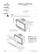
Fig. 6: Sender/receiver unit DHSP-T2VxxEX3K
Purging
The sender/receiver unit must be purged with purge gas (instrument air onsite).
On the standard version, the purge gas flows through the non-return valve in the protective
tube to the measuring opening.
On the high-temperature version, the purge gas flows through the non-return valve in the
protective tube to the measuring opening. In addition, the purge gas flows outside through
the purge openings of the protective tube. This gas cushion provides additional cooling
between the flange with tube and protective tube. Take into consideration that purge gas
consumption is higher in the high-temperature version. (see “Purging with instrument air”,
page 37)
Non-return valve
The non-return valve protects the sender/receiver unit against high temperatures and
sample gas for a short time (few minutes) should the purge gas supply fail.
Electronics unit
Protective tube
Connection for connection cable
Flange with tube
Probe head with receiver optics
Cleaning opening for sender optics
Duct wall
Sight glass
Non-return valve G1/4“
Measuring opening
NL
NOTE:
● The distance between internal duct wall and measuring opening should be at lest
100 mm. For the high-temperature version, the distance should be between 100 mm
and 140 mm so that the measuring device does not protrude too far into the duct
and is not warmed up unnecessarily by the hot sample gas.
Distances see “Fitting the flange with tube”, page 29
NOTE: High-temperature version
To purge the measuring probe, the sender/receiver unit must be fitted in a
flange with tube with an inner diameter of 70 mm. Otherwise temperature dam-
age can occur on the sender/receiver unit when fitted without a flange with
tube.
NOTE:
Device damage is highly probable during longer operation without purge gas
supply. Therefore the sender/receiver unit must always be removed from the
duct when the purge air fails.

20
8020018/ZS56/V2-1/2018-01| SICKOPERATING INSTRUCTIONS | DUSTHUNTER SP100 Ex
Subject to change without notice
2 PRODUCT DESCRIPTION
2.2.2 Flange with tube
The flange with tube is available in different steel grades and dimensions (see “Flange with
tube”, page 87). Selection depends on the wall and isolation thickness of the duct wall (→
nominal length) and the duct material.
Fig. 7: Flange with tube
Material St 37 or
1.4571
NL
Gas tempera-
ture
Sender/receiver unit nominal length (in mm)
435 735
< 150 °C
130, 240 130, 240, 500
NL (in mm)
> 150 °C
240 500
Standard version
Marking for assembly position
Securing bolt
/