Page is loading ...

INSTRUCTION MANUAL
HI98197
USP Compliant
EC, Resistivity, Temperature Meter
for Ultrapure Water

All rights are reserved. Reproduction in whole or in part is prohibited without the written consent of
the copyright owner, Hanna Instruments Inc., Woonsocket, Rhode Island, 02895, USA.
Thank you for choosing a Hanna Instruments product.
Please read this instruction manual carefully before using this instrument. This
manual will provide you with the necessary information for correct use of this
instrument, as well as a precise idea of its versatility.
If you need additional technical information, do not hesitate to e-mail us at
tech@hannainst.com or view our worldwide contact list for a Hanna Instruments
representative near you at www.hannainst.com.
Dear
Customer

3
TABLE OF CONTENTS
PRELIMINARY EXAMINATION ............................................................................................
GENERAL DESCRIPTION ....................................................................................................
FUNCTIONAL DESCRIPTION ...............................................................................................
SPECIFICATIONS ..............................................................................................................
OPERATIONAL GUIDE .......................................................................................................
AUTORANGING ................................................................................................................
TEMPERATURE COMPENSATION ........................................................................................
CONDUCTIVITY VERSUS TEMPERATURE CHART....................................................................
USP MEASUREMENT ........................................................................................................
USP MODE PROCEDURES .................................................................................................
USER CALIBRATION ..........................................................................................................
EC CALIBRATION ..............................................................................................................
GOOD LABORATORY PRACTICE (GLP) ..................................................................................
SETUP ............................................................................................................................
LOG ON DEMAND .............................................................................................................
AUTOLOG ........................................................................................................................
AUTOEND..........................................................................................................................
TEMPERATURE CALIBRATION (for technical personnel only) .................................................
PC INTERFACE ................................................................................................................
BATTERIES REPLACEMENT ................................................................................................
TROUBLESHOOTING GUIDE ...............................................................................................
PROBE MAINTENANCE ......................................................................................................
ACCESSORIES .................................................................................................................
4
5
9
16
18
23
28
37
53
56
66
68
6
11
17
19
27
35
49
55
59
67
70

4
Note: Save all packing material until you are sure that the instrument functions correctly. All defective
items must be returned in the original packing with the supplied accessories.
Remove the instrument from the packing material and examine it carefully to make sure that no damage
has occurred during shipping. If there is any damage, please contact your local Hanna Instruments Office.
Each instrument is supplied with:
• HI763123 Platinum four-ring Conductivity/TDS probe with internal temperature sensor and
1 m (3.3’) cable
• HI605453 Stainless Steel Body for HI763123
• HI7031M 1413 µS/cm calibration standard (230 ml)
• HI7033M 84 µS/cm calibration standard (230 ml)
• HI920015 Micro USB cable
• 100 mL Plastic Beaker (2 pcs.)
• 1.5 V AA Batteries (4 pcs.)
• Instruction Manual and Quick Reference
• Certificate
• Tubing
PRELIMINARY EXAMINATION

5
The HI98197 instrument is state-of-the-art, heavy-duty conductivity meter, designed to provide
laboratory results and accuracy under harsh industrial conditions.
The USP standard compliance makes the instrument useful for ultrapure water determination.
It is provided with a series of new diagnostic features which add an entirely new dimension to the measure-
ment of conductivity, by allowing the user to dramatically improve the reliability of the measurement:
• 7 memorized standards (0.00 µS/cm, 84.0 µS/cm, 1.413 mS/cm, 5.00 mS/cm, 12.88 mS/cm,
80.0 mS/cm and 111.8 mS/cm) for calibration.
• EC calibration up to five calibration points.
• Messages on the graphic LCD for an easy and accurate calibration.
• Diagnostic features to alert the user when the electrode needs cleaning.
• User-selectable “calibration time out” to remind when a new calibration is necessary.
Moreover, they offer an extended temperature range from -20.0 to 120.0 °C (-4.0 to 248.0 °F),
using temperature sensor inside EC electrode.
This instrument can also measure in Resistivity, TDS and Salinity ranges. Three salinity modes are
available:
% NaCl, Practical salinity and Natural seawater scale.
Other features include:
• Temperature source selection
• Temperature automatic compensation, linear or non linear user selectable
• Temperature reference selection 15 °C, 20 °C or 25 °C.
• Temperature coefficient set
• Log on demand up to 400 samples
• Auto Log feature up to 1000 records
• Auto Hold feature, to freeze first stable reading on the LCD
• Lock and user setup Fixed range selection
• GLP feature, to view last calibration data for EC, NaCl
• Probe change recognition
• PC interface
• Probe replatinization
GENERAL DESCRIPTION

6
1) Liquid Crystal Display (LCD).
2) F1, F2, F3 functional keys.
3) / keys to manually increase/decrease the parameters or to scroll between the parameter
list.
4) ON/OFF (
) key, to turn the instrument ON and OFF.
5) LIGHT (
) key to toggle display backlighting.
6) GLP key, to display Good Laboratory Practice information.
7) CAL key, to enter/exit calibration mode.
8) SETUP key, to enter/exit SETUP mode.
9) RCL key, to enter/exit view logged data mode.
10) MODE key to toggle between EC, USP and Salinity ranges.
11) RANGE key, to switch between EC, Resistivity, TDS, NaCl.
12) HELP key to enter/exit contextual help.
13) ESC to leave current mode, exit calibration, setup, help. etc.
FRONT VIEW
14) Electrode DIN connector.
15) USB connector.
TOP VIEW
FUNCTIONAL DESCRIPTION

7
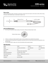
HI605453 - Stainless Steel Body for HI763123
The HI98197 uses the HI763123 platinum four-ring conductivity/resistivity probe for the measurement
of very low conductivity solutions. The HI763123 is capable of measuring the conductivity/resistivity
of high purity water (18.2 MΩ⋅cm @ 25°C). The conductivity readings are displayed with a
0.001 µS/cm resolution and resistivity readings to 0.1 MΩ⋅cm. The measurement of conductivity/
resistivity of high purity water is difficult to perform in an open vessel due to the reaction of carbon
dioxide (CO
2
) in the air with water (H
2
0) to form carbonic acid (H
2
CO
3
). The carbonic acid will
dissociate into hydrogen ions (H
+
) and bicarbonate ions (HCO
3
-
). This dissociation will not only cause
a decrease in pH but also a decrease in resistance (increase in conductance). The HI763123 platinum
four-ring conductivity/resistivity probe has a threaded connection for the insertion of the probe into
a stainless steel flow cell to prevent the diffusion of carbon dioxide into the water. The high purity
water flows through the bottom of the flow cell using a plastic tubing connection and exits out the
side connection to a drain. It is important that the flow of water is from the bottom to ensure that the
water passes through the PEI sleeve of the conductivity/resistivity probe.
When using the flow cell for continuous measurements of high purity water, it is necessary to follow the
next steps:
• Rinse and clean the electrode with purified water. The PEI protective sleeve of the HI763123
should be removed by pulling down. After rinsing with water the probe should be dried and the sleeve
placed back on.
• Insert the HI763123 probe into the flow cell and tighten clockwise. Note that it is easier to screw
the probe into the flow cell when the probe is not connected to the meter.
Connect the supplied plastic tubing to the flow cell.
HI763123-four-ring Conductivity/TDS probe with internal temperature sensor and 1m (3.3’)
cable.
FUNCTIONAL DESCRIPTION

8
• Perform two-point calibration. The first calibration point is done in air (probe inserted in flow
cell without any solution). The air calibration is at 0.001 µS/cm. Once the probe is calibrated to
0.001 µS/cm then a second point is calibrated. It is recommend calibrating the second point with
the HI7033 (84 µS/cm) calibration standard. Holding both tubing (bottom and side) the standard
is introduced into the flow cell through the bottom tubing until there is a 5-7.5 cm (2-3”) column
of solution in the side tubing. While holding both tubes the flow cell should be tapped gently to
dislodge any trapped air. Alternatively the raising and lowering of each tube to move the solution
through the cell. The column of solution should be observed to move as one tube is raised higher
than the other. Once the reading stabilizes the calibration point can be confirmed.
• After calibration the bottom tube of the flow cell is connect to the water source to be tested. The
other tube goes to waste. The water source should be turned on and adjusted to approximately
200-500 mL/minute. A graduated cylinder or beaker can be used to determine the flow rate. The
water should be allowed to flow for at least 1-2 minutes before taking a reading.
• For the measurement of high purity water it is important to use a temperature correction coefficient
(β) of 5.20%/°C. See setup options for changing the temperature correction coefficient. This setting
will adjust each reading by 5.20% for each 1 °C away from the reference temperature (default
25 °C). Using a temperature coefficient of 1.90%/°C (default) will result in higher readings
(>18.2 MΩ⋅cm) being observed for high purity water at a temperature colder than 25 °C.
FUNCTIONAL DESCRIPTION

9
Resistivity
Range
1.0 to 99.9 Ω⋅cm
100 to 999 Ω⋅cm
1.00 to 9.99 KΩ⋅cm
10.0 to 99.9 KΩ⋅cm
100 to 999 KΩ⋅cm
1.00 to 9.99 MΩ⋅cm
10.0 to 100.0 MΩ⋅cm
(autoranging)
Resolution
0.1 Ω⋅cm / 1 Ω⋅cm / 0.01 KΩ⋅cm/ 0.1 KΩ⋅cm/ 1 KΩ⋅cm
0.01 MΩ⋅cm / 0.1 MΩ⋅cm
Accuracy ±1% of reading (±10 Ω⋅cm or 1 digit whichever greater)
TDS
Range
0.00 to 99.99 ppm
100.0 to 999.9 ppm
1.000 to 9.999 g/L
10.00 to 99.99 g/L
100.0 to 400.0 g/L
(autoranging)
Resolution 0.01 ppm / 0.1 ppm / 0.001 g/L / 0.01 g/L / 0.1 g/L
Accuracy ±1% of reading (±0.05 ppm or 1 digit whichever greater)
EC
Range
0 to 400 mS/cm
(shows values up to 1000 mS/cm)
Actual conductivity 1000 mS/cm
0.000 to 9.999 µS/cm
10.00 to 99.99 µS/cm
100.0 to 999.9 µS/cm
1.000 to 9.999 mS/cm
10.00 to 99.99 mS/cm
100.0 to 1000.0 mS/cm (autoranging)
Resolution 0.001 µS/cm / 0.01 µS/cm / 0.1 µS/cm
0.001 mS/cm / 0.01 mS/cm / 0.1 mS/cm
Accuracy ±1% of reading (±0.01 µS/cm or 1 digit whichever greater)
SPECIFICATIONS

10
Temperature
Range -20.0 to 120.0 °C (-4.0 to 248.0 °F)
Resolution 0.1 °C (0.1 °F)
Accuracy ±0.2 °C (±0.4 °F) (excluding probe error)
EC Calibration
Automatic up to five points with seven memorized standards
(0.00 µS/cm, 84.0 µS/cm, 1.413 mS/cm, 5.00 mS/cm,
12.88 mS/cm, 80.0 mS/cm, 111.8 mS/cm)
Cell Constant Setup 0.010 to 10.000
NaCl Calibration
Max. one point only in % range (with HI7037 standard);
use conductivity calibration for other ranges
Implemented Standards USP compliant
EC Probe HI763123 (8 pin DIN, 1 m cable)
Temperature Source Automatic from sensor inside the probe; Manual entry
Temperature Compensation NoTC, Linear, Non Linear ISO/DIS 7888 std
Reference Temperature 15, 20, 25 °C
Temperature Coeficient 0.00 to 10.00 %/°C
TDS Factor 0.40 to 1.00
SPECIFICATIONS
Log on Demand 400 samples
Lot Logging
5, 10, 30 sec,
1, 2, 5, 10, 15, 30, 60, 120, 180 min (max 1000 samples)
Salinity
Range
% NaCl: 0.0 to 400.0 %
Seawater scale: 0.00 to 80.00 (ppt)
Practical salinity: 0.01 to 42.00 (PSU)
Resolution 0.1 % / 0.01 ppt / 0.01 PSU
Accuracy ±1% of reading
Memorized Profiles Up to 10
Measurement Modes Autorange, AutoEnd, LOCK and fixed range
Battery Type / Life
1.5V AA batteries (4 pcs.) / 100h no backlight 25h with
backlight
Auto Power Off User selectable: 5, 10, 30, 60 minutes or disabled

11
INITIAL PREPARATION
The instrument is supplied complete with batteries. See Batteries Replacement for details, page 65.
To prepare the instrument for field measurements close the serial communication socket with proper
stopper (to ensure waterproof protection).
Connect the EC probe to the DIN connector on the top of the instrument. Tighten the thread ring. Make
sure the probe sleeve is properly inserted.
Turn the instrument ON by pressing ON/OFF key.
PC Connectivity Opto-isolated USB
Dimensions 185 x 93 x 35.2 mm (7.3 x 3.6 x 1.4”)
Weight 400 g (14.2 oz)
Environment 0 to 50 °C (32 to 122 °F) max. RH 100% IP 67
OPERATIONAL GUIDE
SPECIFICATIONS
At start-up the display will show the Hanna Instruments logo for a few seconds followed by the
percentage indication of the remaining battery life and the “Loading Log...” message, then enters
the measurement mode.

12
The Auto Power Off feature turns the instrument off after a set period (default 30 min) with no button
pressed to save battery life. To set another period or to disable this feature, see SETUP menu on
page 37. The instrument continues to monitor the inputs and memorize readings if the automatic
logging is enabled and started. To stop autologging press StopLog key or simply power off the
instrument by pressing the ON/OFF key.
The Auto Light Off backlight feature turns the backlight off after a set period (default 1 min) with
no buttons pressed. To set another period or to disable this feature, see SETUP menu on page 37.
MEASUREMENTS
Immerse the probe into the solution to be tested. The sleeve holes must be completely submerged. Tap
the probe repeatedly to remove any air bubbles that may be trapped inside the sleeve.
If needed, press RANGE repeatedly until the desired range (EC, Resistivity, TDS, Salinity) is selected
on the LCD.
Allow for the reading to stabilize. The main LCD line displays the measurement in the selected range,
while the temperature is displayed on the lower LCD line.
EC range
The conductivity range is from 0 to 400 mS/cm . The actual conductivity range (the uncompensated
conductivity) is up to 1000 mS/cm. The instrument will display conductivity readings up to 1000 mS/cm.
Note: The
symbol in front of the temperature reading means that the temperature can be
entered by the user (Manual option selected in SETUP, or temperature out of range).
OPERATIONAL GUIDE

13
TDS range
A conductivity measured value can be corrected to a total dissolved solids value using the TDS factor.
Salinity
The salinity is derived from the conductivity of a sample.
Salt % range
The percent of salinity in a sample is dependent on the sample and the salinity coefficient.
For practical reasons, the salinity of a solution is derived from the salinity of the seawater. Two methods
of calculating the salinity from the conductivity are supported:
• Natural seawater scale
• Practical salinity scale
Natural seawater scale (UNESCO 1966)
According to the definition, salinity of a sample in ppt is calculated using the following formula:
R
T
=
C
T
(sample)
C(35;15)·r
T
r
T
=1.0031·10
-9
T
4
–6.9698·10
-7
T
3
+1.104259·10
-4
T
2
+2.00564·10
-2
T+6.766097·10
-1
R=R
T
+10
-5
R
T
(R
T
–1.0)(T–15.0)[96.7-72.0R
T
+37.3R
T
2
–(0.63+0.21R
T
2
)(T–15.0)]
OPERATIONAL GUIDE
Resistivity range
The reciprocal of the conductivity of a material is the resistivity.

14
According to the definition, salinity of a sample in PSU (practical salinity units) is calculated using
the following formula:
S=-0.08996+28.2929729R+12.80832R
2
–10.67869R
3
+5.98624R
4
–1.32311R
5
where:
R
T
- coefficient;
C
T
(sample) - uncompensated conductivity at T °C;
C(35;15)= 42.914 mS/cm - the corresponding conductivity of KCl solution
containing a mass of 32.4356 g KCl / 1 Kg solution;
r
T
- temperature compensation polynom.
Note: The formula can be applied for temperatures between 10 °C and 31 °C.
To access this range press Mode while in Salinity range until the seawater scale [SW] is
displayed.
Practical salinity scale
This is a practical scale based on the precise measurement of the electrical conductivity of a solution
with a known salinity range.
The relationship derived from the scale relates salinity, conductivity, temperature and pressure
and use a solution with a salinity of 35 ‰ as datum point. This is taken to have a conductivity
of 42.914 mS/cm of 15 °C at standard atmospheric pressure.
OPERATIONAL GUIDE

15
Notes: If the meter displays the top of the range blinking, the reading is out of range.
If the stability indicator “
” blinks, the reading is unstable.
Make sure the meter is calibrated before taking measurements.
If measurements are taken successively in different samples, for accurate readings it is recommend-
ed to rinse the probe thoroughly with deionized water before immersing it into the samples.
TDS reading is obtained by multiplying the EC reading by the TDS factor, which has a default
value of 0.50. It is possible to change the TDS factor in the 0.40 to 1.00 range by entering
SETUP mode.
a
0
= 0.008 b
0
=0.0005
a
1
= -0.1692 b
1
= -0.0056
a
2
= 25.3851 b
2
= -0.0066
a
3
= 14.0941 b
3
= -0.0375
a
4
= -7.0261 b
4
= 0.0636
a
5
= 2.7081 b
5
= -0.0144
c
0
= 0.008
c
1
= 0.0005
X = 400R
T
Y = 100R
T
f (T)= (T-15)/[1+0.0162(T-15)]
Notes: The formula can be applied for salinity values between 0 and 42 PSU.
The formula can be applied for temperatures between -2 °C and 35 °C.
To reach this range press Mode while in Salinity range until the practical salinity scale [PSU] is
displayed.
OPERATIONAL GUIDE
R
T
- coefficient;
C
T
(sample) - uncompensated conductivity at T °C;
C(35,15)= 42.914 mS/cm - the corresponding conductivity of KCl solution
containing a mass of 32.4356 g KCl /1 Kg solution;
r
T
- temperature compensation polynom

16
The EC, Resistivity and TDS scales are autoranging. The meter automatically sets the scale with the
highest possible resolution.
By pressing Lock, the autoranging feature is disabled and the current range is frozen on the LCD.
The “Range: Locked” message is displayed. To restore the autoranging option press “AutoRng”
functional key again.
The autoranging mode is also disabled by selecting a “fixed range” in the SETUP menu. While in fixed
range mode the instrument will display the readings with the fixed resolution. A maximum of 6 digits
can be displayed. The top of the fixed range is displayed blinking when the reading exceeds this value.
To disable fixed range mode enter SETUP and select autoranging mode.
Note: Autoranging is automatically restored if the range is changed, if the calibration mode
is entered, or if the meter is turned off and back on again.
AUTORANGING
The probes designed to work with this instrument have an internal ID identification. Every time the
instrument detects probe changing, it reminds the user to update the cell constant of the new probe
being used and to calibrate in the appropriate EC range.
OPERATIONAL GUIDE

17
Two selectable temparature sources are available: reading directly from the sensor inside the probe
or manual entry.
Three options of compensating temperature are available:
Linear Temperature Compensation: The conductivity of a solution with a specific electrolyte
concentration changes with temperature. The relationship of the change in conductivity as a function
of temperature is described by a solution’s temperature coefficient. This coefficient varies with each
solution and is user selectable (see SETUP mode).
Non Linear Temperature Compensation: for natural water measurements.
The conductivity of natural water shows strong non-linear temperature behavior.
A polynomial relationship is used to improve the accuracy of the calculated results.
Note: Conductivity measurements of natural water can only be performed at temperatures
ranging from 0 to 36 °C. Otherwise the “Out T range” message will be displayed blinking.
No Temperature Compensation (No TC): The temperature shown on the LCD is not taken into
account.
To select the desired option enter SETUP menu (see page 37).
If the temperature is out of the -20 °C - 120 °C range the instrument will do no temperature
compensation.
TEMPERATURE COMPENSATION

18
The conductivity of an aqueous solution is the measure of its ability to carry an electrical current by
means of ionic motion.
The conductivity invariably increases as the temperature rises.
It is affected by the type and number of ions in the solution and by the viscosity of the solution itself.
Both parameters are temperature dependent. The dependency of conductivity on temperature is
expressed as a relative change per Celsius degree at a particular temperature, commonly as percent
per °C (%/°C).
The following table lists the temperature dependence of the Hanna Instruments calibration buffers.
°C °F
HI7030
HI8030
(µS/cm)
HI7031
HI8031
(µS/cm)
HI7033
HI8033
(µS/cm)
HI7034
HI8034
(µS/cm)
HI7035
HI8035
(µS/cm)
HI7039
HI8039
(µS/cm)
0
5
10
15
16
17
18
19
20
21
22
23
24
25
26
27
28
29
30
31
32
41
50
59
60.8
62.6
64.4
66.2
68
69.8
71.6
73.4
75.2
77
78.8
80.6
82.4
84.2
86
87.8
7150
8220
9330
10480
10720
10950
11190
11430
11670
11910
12150
12390
12640
12880
13130
13370
13620
13870
14120
14370
776
896
1020
1147
1173
1199
1225
1251
1278
1305
1332
1359
1386
1413
1440
1467
1494
1521
1548
1575
64
65
67
68
70
71
73
74
76
78
79
81
82
84
86
87
89
90
92
94
48300
53500
59600
65400
67200
68500
69800
71300
72400
74000
75200
76500
78300
80000
81300
83000
84900
86300
88200
90000
65400
74100
83200
92500
94400
96300
98200
100200
102100
104000
105900
107900
109800
111800
113800
115700
117700
119700
121800
123900
2760
3180
3615
4063
4155
4245
4337
4429
4523
4617
4711
4805
4902
5000
5096
5190
5286
5383
5479
5575
CONDUCTIVITY VERSUS TEMPERATURE CHART

19
Pharmaceutical laboratories working in the US market are obliged to respect the regulations set down
by the US Pharmacopoeia (USP). The 5
th
supplement of USP24-NF19 lays down the rules for checking
the quality of pure or fully deionized water used for the production of injection products.
The conductivity of water provides information on its chemical composition. It is therefore logical that
conductivity is the main parameter to measure.
The conductivity of water is a measure of the ion mobility through this water. The conductivity partly
depends on the pH, the temperature and the amount of atmospheric carbon dioxide, which has been
dissolved in water to form ions (intrinsic conductivity). The conductivity also depends on the chloride,
sodium and ammonium ions initially present in water (extraneous conductivity).
The conductivity (intrinsic and extraneous) of the water is measured at Stage 1 and compared to
values listed in a table to evaluate if the studied water is suitable or not for use in pharmaceutical
applications. If the sample fails Stage 1, additional tests have to be performed (Stage 2 and 3) in
order to determine if the excessive conductivity value is due to intrinsic factors or extraneous ions.
USP Requirements
Automatic temperature correction must not be used.
Instrument specifications
Minimum resolution of 0.1 µS/cm on the lowest range. Excluding the cell accuracy, the instrument
accuracy must be ±0.1 µS/cm.
Meter calibration
It is accomplished by replacing the conductivity cell with precision resolution traceable to primary
standards (accurate to ±0.1 % of the stated value) or an equivalently accurate resistance device.
Cell calibration
Meter conductivity must be measured accurately using calibrated instrumentation. The conductivity
cell constant must be known in ±2%.
Before starting water analysis calibrate in the lowest EC range or set the probe cell constant (enter
the value written in the calibration certificate delivered with the probe).
Stage 1
Determine the temperature and conductivity of the water.
• Rinse the probe carefully with deionized water. Check that the four-rings, sleeve holes and the
temperature sensor are immersed in the sample and that no air bubbles are trapped. Connect
the probe to the meter, enter USP mode and press the Stage 1 key. The instrument will perform
a temperature and conductivity measurement (using a non-temperature corrected conductivity
reading).
USP MEASUREMENT

20
Temperature
°C
0 0.6
5 0.8
10 0.9
15 1.0
20 1.1
25 1.3
30 1.4
35 1.5
40 1.7
45 1.8
50 1.9
55 2.1
60 2.2
65 2.4
70 2.5
75 2.7
80 2.7
85 2.7
90 2.7
95 2.9
100 3.1
• Using the Stage 1 temperature and conductivity requirement table the corresponding conductivity
limit at that temperature is determined.
• If the measured conductivity is not greater than the table value the water meets the requirements
of the test for conductivity. If the conductivity is higher than the table value, proceed with Stage 2.
Stage 1 table
Temperature and conductivity requirements *
(for the non-temperature compensated conductivity measurements only)
(*) Values from USP - NF Fifth Supplement
Conductivity
µS/cm
USP MEASUREMENT
Physical Tests / Water Conductivity (645) 3465-3467
/