Page is loading ...

Millerfi
February
1994
Form:
OM-1534D
Effective
With
Serial
No.
KB1
39723
OWNERS
MANUAL
CO
~
U
Read
and
follow
these
instructions
and
all
safety
blocks
carefully.
Have
only
trained
and
qualified
persons
install,
operate,
or
service
this
unit.
Call
your
distributor
if
you
do
not
understand
the
directions.
j~
~
Give
this
manual
to
the
operator.
~I~fl
For
help,
call
your
distributor
or:
MILLER
Electric
Mfg.
Co.,
P.O.
Box
1079,
Appleton,
WI
54912
414-734-9821
S-44G
L
cover
7/93
ST-045
405-A
'
1994
MLLER
Elect,ic
Mfg.
Co.
PRINTED
IN
USA

I
-I
J
MILLERS
TRUE
BLUETM
LIMITED
WARRANTY
Effective
January
1,
1992
(Equipment
with
a
serial
number
preface
of
KC
or
newer)
This
limited
warranty
supersedes
all
previous
MILLER
warranties
and
is
exclusive
with
no
other
guarantees
or
warranties
expressed
or
implied.
L
LIMITED
WARRANTY
Subject
tothe
terms
and
conditions
below,
MILLER
Electnc
Mfg.
Co.,
Appleton,
Wisconsin,
warrants
to
its
onginal
retail
purchaser
that
new
MILLER
equipment
sold
after
the
effective
date
ot
this
limited
warranty
is
tree
of
de
fects
in
material
and
workmanship
at
the
time
it
is
shipped
by
MILLER.
THIS
WAR
RANTY
IS
EXPRESSLY
IN
LIEU
OF
ALL
OTHER
WARRANTIES,
EXPRESS
OR
IMPLIED,
INCLUDING
THE
WARRANTIES
OF
MERCHANTABILITY
AND
FIT
NESS.
Within
the
warranty
periods
listed
below,
MILLER
will
repair
or
replace
any
war
ranted
pails
orcomponents
that
fail
due
to
such
defects
in
material
orworkmanship.
MILLER
must
be
notified
in
writing
within
thirty
(30)
days
of
such
defect
or
failure,
at
which
time
MILLER
will
provide
instructions
on
the
warranty
claim
procedures
to
be
followed.
MILLER
shall
honor
warranty
claims
on
warranted
equipment
listed
below
in
the
event
of
such
a
failure
within
the
warranty
time
periods.
All
warranty
time
periods
start
on
the
date
that
the
equipment
was
delivered
to
the
original
retail
purchaser,
or
one
year
after
the
equipment
is
sent
to
the
distributor.
1.
5
Years
Parts3
Years
Labor
Original
main
power
rectifiers
2.
3
Years
Pails
and
Labor
Transformer/Rectifier
Power
Sources
Plasma
Arc
Cutting
Power
Sources
Semi-Automatic
and
Automatic
Wire
Feeders
*
Robots
3.
2
Years
Pails
and
Labor
Engine
Driven
Welding
Generators
(NOTE:
Engines
are
warranted
separately
by
the
engine
manufacturer
for
a
period
of
two
years.)
Air
Compressors
*
Remote
Controls
Accessory
Kits
Replacement
Pails
MILLERS
True
Blue~
Limited
Warranty
shall
not
apply
to:
1.
Items
furnished
by
MILLER,
but
manufactured
by
others,
such
as
engines
or
trade
accessories.
These
items
are
covered
by
the
manufacturers
warranty,
if
any.
2.
Consumable
components;
such
as
contact
tips,
cutting
nozzles,
contactors
and
relays
or
parts
that
fail
due
to
normal
wear.
3.
Equipment
that
has
been
modified
by
any
party
other
than
MILLER,
or
equip
ment
that
has
been
impropeily
installed,
improperty
operated
or
misused
based
upon
industry
standards,
or
equipment
which
has
not
had
reasonable
and
necessary
maintenance,
or
equipment
which
has
been
used
for
operation
outside
of
the
specifications
for
the
equipment.
MILLER
PRODUCTS
ARE
INTENDED
FOR
PURCHASEAND
USE
BYCOMMER
CIAL/INDUSTRIAL
USERS
AND
PERSONS
TRAINED
AND
EXPERIENCED
IN
THE
USE
AND
MAINTENANCE
OF
WELDING
EOUIPMENT.
In
the
event
of
a
warranty
claim
covered
by
this
warranty,
the
exclusive
remedies
shall
be,
at
MILLERS
option:
(1)
repaifl
or
(2)
replacement;
or,
where
authorized
in
writing
by
MILLER
inappropriate
cases,
(3)
the
reasonable
cost
of
repair
or
replace
ment
Stan
authorized
MILLER
service
station;
or
(4)
payment
of
or
credit
forthe
pur
chase
price
(less
reasonable
depreciation
bssed
upon
actual
use)
upon
return
of
the
goods
at
customers
risk
and
expense.
MILLERS
option
of
repair
or
replacement
will
be
FOB.,
Factory
at
Appleton,
Wisconsin,
or
FOB.
at
a
MILLER
authorized
ser
vice
facility
as
determined
by
MILLER.
Therefore
no
compensation
or
reimburse
ment
for
trsnsportation
costs
of
any
kind
will
be
allowed.
TO
THE
EXTENT
PERMITTED
BY
LAW,
THE
REMEDIES
PROVIDED
HEREIN
ARE
ThE
SOLE
AND
EXCLUSIVE
REMEDIES.
IN
NO
EVENTSHALL
MILLER
BE
LIABLE
FOR
DIRECT,
INDIRECT,
SPECIAL,
INCIDENTALOR
CONSEQUENTIAL
DAMAGES
(INCLUDING
LOSS
OF
PROFIT),
WHETHER
BASED
ON
CON
TRACT,
TORT
OR
ANY
OTHER
LEGAL
THEORY.
ANY
EXPRESS
WARRANTY
NOT
PROVIDED
HEREIN
AND
ANY
IMPLIED
WAR
RANTY,
GUARANTY
OR
REPRESENTATiON
AS
TO
PERFORMANCE,
AND ANY
REMEDY
FOR
BREACH
OF
CONTRACT
TORT
OR
ANY
OTHER
LEGAL
THEORY
WHICH,
BUT
FOR
THIS
PROVISION,
MIGHT
ARISE
BY
IMPLICATION,
OPERA11ON
OF
LAW,
CUSTOM
OF
TRADE
OR
COURSE
OF
DEALING,
IN
CLUDING
ANY
IMPLIED
WARRANTY
OF
MERCHANTABILITY
OR
FITNESS
FOR
PARTICULAR
PURPOSE,
WITH
RESPECTTO
ANY
AND
ALL
EQUIPMENT
FURNISHED
BY
MILLER
IS
EXCLUDED
AND
DISCLAIMED
BY
MILLER.
Some
states
in
the
U.S.A.
do
not
allow
limitations
of
how
long
an
implied
warranty
lasts,
or
the
exclusion
of
incidental,
indirect,
special
or
consequential
damages,
so
the
above
limitation
or
exclusion
may
not
apply
to
you.
This
warranty
provides
spe
cific
legal
rights,
and
other
rights
may
be
available,
but
may
vary
from
state
to
state.
In
Canada,
legislation
in
some
provinces
provides
for
certain
additional
warranties
or
remedies
other
than
as
stated
herein,
and
to
the
extent
that
they
may
not
be
waived,
the
limitations
and
exclusions
sot
out
above
may
not
apply.
This
Limited
Warranty
provides
specific
legal
rights,
and
other
rights
may
be
available,
but
may
vary
from
province
to
province.
4.
1
Year
Pails
and
Labor
Motor
Driven
Guns
Process
Controllers
Water
Coolant
Systems
HF
Units
Grids
Spot
Welders
Load
Banks
SDX
Transformers
*
Running
Gear/Trailers
Field
Options
(NOTE:
Field
options
are
covered
under
True
BlueTM
for
the
remaining
warranty
period
of
the
product
they
are
installed
in,
or
for
a
minimum
of
one
year
whichever
is
greater.)
5.
6
Months
Batteries
6.
90
Days
Pails
and
Labor
MIG
Guns/TIG
Torches
Plasma
Cutting
Torches
~~1
U
L
RECEIVING-HANDLING
Before
unpacking
equipment,
check
carton
for
any
damage
that
may
have
occurred
during
shipment.
File
any
claims
for
loss
or
damage
with
the
delivering
carrier.
Assistance
for
filing
or
settling
claims
may
be
obtained
from
distributor
and/or
equipment
manufacturers
Transportation
Department.
When
requesting
information
about
this
equipment,
always
provide
Model
Designation
and
Serial
or
Style
Number.
Use
the
following
spaces
to
record
Model
Designation
and
Serial
or
Style
Number
of
your
unit.
The
information
is
located
on
the
rating
label
or
nameplate.
Model
__________
Serial
or
Style
No.
Date
of
Purchase
miller
9/93

ERRATA
SHEET
April
25,
1994
FORM:
OM-1534~
After
this
manual
was
printed,
refinements
in
equipment
design
occurred.
This
sheet
lists
exceptions
to
data
appearing
later
in
this
manual.
AMENDMENT
TO
SECTION
4
INSTALLATION
OR
RELOCATION
~p=~
~
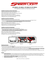
Amend
Figure
4-3.
Wire
Reel
And
Reel-Type
Wire
Installation
~
Ret.
ST-127
308-B
/
Ref.
ST-i
5799
-A
Amend
Section
4-9B.
WELDING
WIRE
INSTALLATION:
Installation
Of
Wire
Reel
And
Reel-Type
Wire
1.
Remove
retaining
ring
and,
if
applicable,
wire
reel
assembly
from
hub.
2.
Lay
wire
reel
assembly
flat
on
table
or
floor.
3.
Pull
lock
and
turn.
Remove
spanner
nut
from
wire
reel
assembly.
4.
Remove
wire
retainer,
and
install
wire
onto
wire
reel.
Be
sure
wire
feeds
off
bottom
of
reel.
5.
Reinstall
wire
retainer.
Tighten
spanner
nut
until
lock
is
in
position
over
hole
in
wire
retainer.
Pull
lock
and
tu
insert
locking
pin
into
wire
retainer.
6.
Slide
wire
reel
assembly
onto
hub,
and
turn
assembly
until
hub
guide
pin
is
seated
in
reel.
7.
Reinstall
retaining
ring
onto
hub.
Spanner
Nut
Wire
Retainer
Retaining
Ring
Wire
Reei
Hub
FIgure
4-3.
Wire
Reel
And
Reel-Type
Wire
Installation
to

AMENDMENT
TO
SECTION
9
PARTS
LIST
Amend
Parts
List
as
follows:
**First
digit
represents
page
no
digits
following
dash
represent
item
no.
+When
ordering
a
component
originally
displaying
a
precautionary
label,
the
label
should
also
be
ordered.
BE
SURE
TO
PROVIDE
MODEL
AND
SERIAL
NUMBER
WHEN
ORDERING
REPLACEMENT
PARTS.
Part
No.
Replaced
With
Description
Quantity
.
21-3
...
124
904
.
.
..
168
103
..
NUT,
spanner
retaining
(Eff
w/KE621
826)
(consisting
of)
1
.
21-4
...
124
905
.
.
.
+168
104
..
RETAINER,
spool
support
(Eff
w/KE621826)
(consisting
of)
1
166
594
. . .
.
LABEL,
caution
falling
wire
reel
can
cause
damage
1
.
24-9
...
079
669
. .
..
166
071
..
LEVER,
mtg
pressure
gear
(Eff
w/KE557397)
1
24-12
..
046
619
.
.
..
166
338
..
LEVER,
mtg
pressure
gear
(Eff
wIKE557397)
1
.
24-
Added
.
.
..
166
072
..
SPACER,
gear
(Eff
w/KE557397)
4
OM-1534D
Page
2

OM-1534D-~
4
TABLE
OF
CONTENTS
Section
No.
Page
No.
SECTION
1
SAFETY
RULES
FOR
OPERATION
OF
ARC
WELDING
POWER
SOURCE
1-1.
Introduction
1
1-2.
General
Precautions
1
1-3.
Arc
Welding
4
1-4.
Standards
Booklet
Index
5
SECTION
2
SAFETY
PRECAUTIONS
AND
SIGNAL
WORDS
2-1.
General
Information
And
Safety
6
2-2.
Safety
Alert
Symbol
And
Signal
Words
6
SECTION
3
SPECIFICATIONS
3-1.
Description
7
SECTION
4
INSTALLATION
OR
RELOCATION
4-1.
Location
7
4-2.
Drive
Motor
Vent
Screw
7
4-3.
Wire
Guide
And
Drive
Roll
Installation
8
4-4.
Welding
Gun
Connections
8
4-5.
Voltage
Sensing
Lead
Connection
9
4-6.
Shielding
Gas
Connection
(Models
With
Optional
Gas
Valve)
9
4-7.
115
Volts
AC
Connection
(Models
With
Optional
Gas
Valve)
9
4-8.
Welding
Power
Source/Wire
Feeder
Weld
Cable
Connections
9
4-9.
Welding
Wire
Installation
10
4-10.
WeldingWireThreading
10
SECTION
5-OPERATOR
CONTROLS
5-1.
Arc
Length
Control
11
5-2.
Jog
Button
12
5-3.
Polarity
Switch
12
5-4.
Optional
Voltmeter
12
5-5.
Optional
Remote
Jog
Switch
12
SECTION
6-
SEQUENCE
OF
OPERATION
6-1.
Flux
Core
Arc
Welding
(FCAW)
And
Gas
Metal
Arc
Welding
(GMAW)
13
6-2.
Shutting
Down
13
SECTION
7
MAINTENANCE
&
TROUBLESHOOTING
7-1.
Routine
Maintenance
14
7-2.
Aligning
Motor
Gear
And
Drive
Gears
14
7-3.
Reinstallation
Of
Hub
Assembly
15
7-4.
Overload
Protection
15
7-5.
Brush
Inspection
And
Replacement
16
7-6.
Troubleshooting
17

Section
No
Page
No.
SECTION
8
ELECTRICAL
DIAGRAMS
Diagram
8-1.
Circuit
Diagram
18
SECTION
9
PARTS
LIST
Figure
9-1.
Main
Assembly
20
Optional
Equipment
22
Figure
9-2.
Switch,
Magnetic
Blowout
23
Figure
9-3.
Wire
Drive
&
Gears
24
LIST
OF
CHARTS
AND
TABLES
Table
3-1.
Specifications
7
Table
5-1.
Arc
Voltage
Wire
Speed
12
Table
7-1.
Maintenance
Schedule
14
Table
7-2.
Troubleshooting
17
Table
9-1.
Drive
Roll
&
Wire
Guide
Kits
25

SECTION
1
-
SAFETY
RULES
FOR
OPERATION
OF
ARC
WELDING
POWER
SOURCE
1-1.
INTRODUCTION
We
learn
by
experience.
Learning
safety
through
per
sonal
experience,
like
a
child
touching
a
hot
stove
is
harmful, wasteful,
and
unwise.
Let
the
experience
of
others
teach
you.
Safe
practices
developed
from
experience
in
the
use
of
welding
and
cutting
are
described
in
this
manual.
Re
search,
development,
and
field
experience
have
evolved
reliable
equipment
and
safe
installation,
opera
tion,
and
servicing
practices.
Accidents
occur
when
equipment
is
improperly
used
or
maintained.
The
rea
son
for
the
safe
practices
may
not
always
be
given.
Some
are
based
on
common
sense,
others
may
require
technical
volumes
to
explain.
It
is
wiser
to
follow
the
rules.
Read
and
understand
these
safe
practices
before
at
tempting
to
install,
operate,
or
service
the
equipment.
Comply
with
these
procedures
as
applicable
to
the
par
ticular
equipment
used
and
their
instruction
manuals,
for
personal
safety
and
for
the
safety
of
others.
Failure
to
observe
these
safe
practices
may
cause
seri
ous
injury
or
death.
When
safety
becomes
a
habit,
the
equipment
can
be
used
with
confidence.
These
safe
practices
are
divided
into
two
Sections:
1-General
Precautions,
common
to
arc
welding
and
cut
ting;
and
2-Arc
Welding
(and
Cutting)
(only).
Reference
standards:
Published
Standards
on
safety
are
also
available
for
additional
and
more
complete
pro
cedures
than
those
given
in
this
manual.
They
are
listed
in
the
Standards
Index
in
this
manual.
ANSI
Z49.1
is
the
most
complete.
The
National
Electrical
Code,
Occupational
Safety
and
Health
Administration,
local industrial
codes,
and
local
inspection
requirements
also
provide
a
basis
for
equip
ment
installation,
use,
and
service.
1-2.
GENERAL
PRECAUTIONS
Different
arc
welding
processes,
electrode
alloys,
and
fluxes
can
produce
different
fumes,
gases,
and
radiation
levels.
In
addition
to
the
information
in
this
manual,
be
sure
to
consult
flux
and
electrode
manu
facturers
Material
Safety
Data
Sheets
(MSDSs)
for
specific
technical
data
and
precautionary
measures
concerning
their
material.
A.
Burn
Prevention
Wear
protective
clothing-gauntlet
gloves
designed
for
use
in
welding,
hat,
and
high
safety-toe
shoes.
Button
shirt
collar
and
pocket
flaps,
and
wear
cuff
less
trousers
to
avoid
entry
of
sparks
and
slag.
Wear
helmet
with
safety
goggles
and
glasses
with
side
shields
underneath,
appropriate
filter
lenses
or
plates
(protected
by
clear
cover
glass).
This
is
a
MUST
for
welding
or
cutting,
(and
chipping)
to
protect
the
eye
from
radiant
energy
and
flying
metal.
Replace
cover
glass
when
broken,
pitted,
or
spattered.
See
1-3A.2.
Avoid
oily
or
greasy
clothing.
A
spark
may
ignite
then1.
Hot
metal
such
as
electrode
stubs
and
workpiece~
should
never
be
handled
without
gloves.
Medical
first
aid
and
eye
treatment.
First
aid
facilitie~
and
a
qualified
first
aid
person
should
be
available
for
each
shift
unless
medical
facilities
are
close
by
for
irri
mediate
treatment
of
flash
burns
of
the
eyes
and
skih
burns.
Ear
plugs
should
be
worn
when
working
on
overhead
dr
in
a
confined
space.
A
hard
hat
should
be
worn
wheb
others
work
overhead.
Flammable
hair
preparations
should
not
be
used
by
pe
-
Sons
intending
to
weld
or
cut.
B.
Toxic
Fume
Prevention
Severe
discomfort,
illness
or
death
can
result
fro
i
fumes,
vapors,
heat,
or
oxygen
enrichment
or
depletio
that
welding
(or
cutting)
may
produce.
Prevent
the~
with
adequate
ventilation
as
described
in
ANSI
Sta~
dard
Z49.1
listed
in
Standards
Index.
NEVER
ventila
with
oxygen.
Lead-,
cadmium
-,zinc-,
mercury
-,
and
beryllium-bea
ing
and
similar
materials,
when
welded
(or
cut)
may
pr
duce
harmful
concentrations
of
toxic
fumes.
Adequa~
local
exhaust
ventilation
must
be
used,
or
each
perso
in
the
area
as
well
as
the
operator
must
wear
an
air-su
plied
respirator.
For
beryllium,
both
must
be
used.
Metals
coated
with
or
containing
materials
that
e
toxic
fumes
should
not
be
heated
unless
coating
is
r
moved
from
the
work
surface,
the
area
is
well
ventilate
and,
if
necessary,
while
wearing
an
air-supplied
respir~
tor.
Work
in
a
confined
space
only
while
it
is
being
ventilated
and,
if
necessary,
while
wearing
an
air-supplied
respir~
tor.
Gas
leaks
in
a
confined
space
should
be
avoidec
Leaked
gas
in
large
quantities
can
change
oxygen
co~
centration
dangerously.
Do
not
bring
gas
cylinders
into
confined
space.
Leaving
confined
space,
shut
OFF
gas
supply
at
sour
to
prevent
possible
accumulation
of
gases
in
the
space
downstream
valves
have
been
accidentally
opened
left
open.
Check
to
be
sure
that
the
space
is
safe
befo
e
re-entering
it.
Vapors
from
chlorinated
solvents
can
be
decompos
by
the
heat
of
the
arc
(or
flame)
to
form
PHOSGENE
highly
toxic
gas,
and
other
lung
and
eye
irritating
prc
ucts.
The
ultraviolet
(radiant)
energy
of
the
arc
can
at
decompose
trichloroethylene
and
perchloroethylei
vapors
to
form
phosgene.
DO
NOT
WELD
or
cut
whe
n
n
e
e
n
~it
d
1
a
if
)r
d
a
re
OM-1
534
Pag~
1

solvent
vapors
can
be
drawn
into
the
welding
or
cutting
atmosphere
or
where
the
radiant
energy
can
penetrate
to
atmospheres
containing
even
minute
amounts
of
trichioroethylene
or
perchloroethylene.
C.
Fire
and
Explosion
Prevention
Causes
of
fire
and
explosion
are:
combustibles
reached
by
the
arc,
flame,
flying
sparks,
hot
slag
or
heated
mate
rial;
misuse
of
compressed
gases
and
cylinders;
and
short
circuits.
BE
AWARE
THAT
flying
sparks
or
falling
slag
can
pass
through
cracks,
along
pipes,
through
windows
or
doors,
and
through
wall
or
floor
openings,
out
of
sight
of
the
goggled
operator.
Sparks
and
slag
can
fly
35
feet.
To
prevent
fires
and
explosion:
Keep
equipment
clean
and
operable,
free
of
oil,
grease,
and
(in
electrical
parts)
of
metallic
particles
that
can
cause
short
circuits.
If
combustibles
are
in
area,
do
NOT
weld
or
cut.
Move
the
work
if
practicable,
to
an
area
free
of
combustibles.
Avoid
paint
spray
rooms,
dip
tanks,
storage
areas,
venti
lators.
If
the
work
cannot
be
moved,
move
combustibles
at
least
35
feet
away
out
of
reach
of
sparks
and
heat;
or
protect
against
ignition
with
suitable
and
snug-fitting,
fire-resistant
covers
or
shields.
Walls
touching
combustibles
on
opposite
sides
should
not
be
welded
on
(or
cut).
Walls,
ceilings,
and
floor
near
work
should
be
protected
by
heat-resistant
covers
or
shields.
Fire
watcher
must
be
standing
by
with
suitable
fire
extin
guishing
equipment
during
and
for
some
time
after
weld
ing
or
cutting
if:
a.
appreciable
combustibles
(including
building
construction)
are
within
35
feet
b.
appreciable
combustibles
are
further
than
35
feet
but
can
be
ignited
by
sparks
c.
openings(concealedorvisible)
infloorsorwalls
within
35
feet
may
expose
combustibles
to
sparks
d.
combustibles
adjacent
to
walls,
ceilings,
roofs,
or
metal
partitions
can
be
ignited
by
radiant
or
conducted
heat.
Hot
work
permit
should
be
obtained
before
operation
to
ensure
supervisors
approval
that
adequate
precau
tions
have
been
taken.
After
work
is
done,
check
that
area
is
free
of
sparks,
glowing
embers,
and
flames.
An
empty
container
that
held
combustibles,
or
that
can
produce
flammable
or
toxic
vapors
when
heated,
must
never
be
welded
on
or
cut,
unless
container
has
first
been
cleaned
as
described
in
AWS
Standard
A6.O,
listed
7
in
Standards
Index.
This
includes:
a
thorough
steam
or
caustic
cleaning
(or
a
solvent
or
water
washing,
depending
on
the
combusti
bles
solubility)
followed
by
purging
and
inerting
with
ni
trogen
or
carbon
dioxide,
and
using
protective
equip
ment
as
recommended
in
A6.O.
Waterfilling
just
below
working
level
may
substitute
for
inerting.
A
container
with
unknown
contents
should
be
cleaned
(see
preceding
paragraph).
Do
NOT
depend
on
sense
of
smell
or
sight
to
determine
if
it
is
safe
to
weld
or
cut.
Hollow
castings
or
containers
must
be
vented
before
welding
or
cutting.
They
can
explode.
Explosive
atmospheres.
Never
weld
or
cut
where
the
air
may
contain
flammable
dust,
gas,
or
liquid
vapors
(such
as
gasoline).
D.
Compressed
Gas
Equipment
Standard
precautions.
Comply
with
precautions
in
this
manual,
and
those
detailed
in
CGA
Standard
P-i,
SAFE
HANDLING
OF
COMPRESSED
GASES
IN
CYLIN
DERS,
listed
11
in
Standards
Index.
1.
Pressure
Regulators
Regulator
relief
valve
is
designed
to
protect
only
the
regulator
from
overpressure;
it
is
not
intended
to
protect
any
downstream
equipment.
Provide
such
protection
with
one
or
more
relief
devices.
Never
connect
a
regulator
to
a
cylinder
containing
gas
other
than
that
for
which
the
regulator
was
designed.
Remove
faulty
regulator
from
service
immediately
for
repair
(first
close
cylinder
valve).
The
following
symp
toms
indicate
a
faulty
regulator:
Leaks-if
gas
leaks
externally.
Excessive
Creep-if
delivery
pressure
continues
to
rise
with
downstream
valve
closed.
Faulty
Gauge-if
gauge
pointer
does
not
move
off
stop
pin
when
pressurized,
nor
returns
to
stop
pin
after
pres
sure
release.
Repair.
Do
NOT
attempt
to
repair.
Send
faulty
regulators
for
repair
to
manufacturers
designated
repair
center,
where
special
techniques
and
tools
are
used
by
trained
personnel.
2.
Cylinders
Cylinders
must
be
handled
carefully
to
prevent
leaks
and
damage
to
their
walls,
valves,
or
safety
devices:
Avoid
electrical
circuit
contact
with
cylinders
including
third
rails,
electrical
wires,
or
welding
circuits.
They
can
produce
short
circuit
arcs
that
may
lead
to
a
serious
ac
cident.
(See
1-3G.)
ICC
or
DOT
marking
must
be
on
each
cylinder.
It
is
an
assurance
of
safety
when
the
cylinder
is
properly
han
dled.
Identifying
gas
content.
Use
only
cylinders
with
name
of
gas
marked
on
them;
do
not
rely
on
color
to
identify
gas
content.
Notify
supplier
if
unmarked.
NEVER
DEFACE
or
alter
name,
number,
or
other
markings
on
a
cylinder.
It
is
illegal
and
hazardous.
Empties:
Keep
valves
closed,
replace
caps
securely;
mark
MT;
keep
them
separate
from
FULLS
and
return
promptly.
OM-1
534
Page
2

Prohibited
use.
Never
use
a
cylinder
or
its
contents
for
other
than
its
intended
use,
NEVER
as
a
support
or
roller.
Locate
or
secure
cylinders
so
they
cannot
be
knocked
over.
Passageways
and
work
areas.
Keep
cylinders
clear
of
areas
where
they
may
be
struck.
Transporting
cylinders.
With
a
crane,
use
a
secure
sup
port
such
as
a
platform
or
cradle,
Do
NOT
lift
cylinders
off
the
ground
by
their
valves
or
caps,
or
by
chains,
slings,
or
magnets.
Do
NOT
expose
cylinders
to
excessive
heat,
sparks,
slag,
and
flame,
etc.
that
may
cause
rupture.
Do
not
al
low
contents
to
exceed
130F.
Cool
with
water
spray
where
such
exposure
exists.
Protect
cylinders
particularly
valves
from
bumps,
falls,
falling
objects,
and
weather.
Replace
caps
securely
when
moving
cylinders.
Stuck
valve.
Do
NOT
use a
hammer
or
wrench
to
open
a
cylinder
valve
that
can
not
be
opened
by
hand.
Notify
your
supplier.
Mixing
gases.
Never
try
to
mix
any
gases
in
a
cylinder.
Never
refill
any
cylinder.
Cylinder
fittings
should
never
be
modified
or
ex
changed.
3.
Hose
Prohibited
use.
Never
use
hose
other
than
that
de
signed
for
the
specified
gas.
A
general
hose
identifica
tion
rule
is:
red
for
fuel
gas,
green
for
oxygen,
and
black
for
inert
gases.
Use
ferrules
or
clamps
designed
for
the
hose
(not
ordi
nary
wire
or
other
substitute)
as a
binding
to
connect
hoses
to
fittings.
No
copper
tubing
splices.
Use
only
standard
brass
fit
tings
to
splice
hose.
Avoid
long
runs
to
prevent
kinks
and
abuse.
Suspend
hose
off
ground
to
keep
it
from
being
run
over,
stepped
on,
or
otherwise
damaged.
Coil
excess
hose
to
prevent
kinks
and
tangles.
Protect
hose
from
damage
by
sharp
edges,
and
by
sparks,
slag,
and
open
flame.
Examine
hose
regularly
for
leaks,
wear,
and
loose
con
nections.
Immerse
pressured
hose
in
water;
bubbles
in
dicate
leaks.
Repair
leaky
or
worn
hose
by
cutting
area
out
and
splic
ing
(1-2D3).
Do
NOT
tape.
4.
Proper
Connections
Clean
cylinder
valve
outlet
of
impurities
that
may
clog
orifices
and
damage
seats
before
connecting
regulator.
Except
for
hydrogen,
crack
valve
momentarily,
pointin
outlet
away
from
people
and
sources
of
ignition.
Wip
with
a
clean
lintless
cloth.
Match
regulator
to
cylinder.
Before
connecting,
chec
that
the
regulator
label
and
cylinder
marking
area,
an
that
the
regulator
inlet
and
cylinder
outlet
matci
NEVER
CONNECT
a
regulator
designed
for
a
particulE
gas
or
gases
to
a
cylinder
containing
any
other
gas.
Tighten
connections.
When
assembling
threaded
cor
nections,
clean
and
smooth
seats
where
necessar
Tighten.
If
connection
leaks,
disassemble,
clean,
an
retighten
using
properly
fitting
wrench.
Adapters.
Use
a
CGA
adapter
(available
from
your
su~
plier)
between
cylinder
and
regulator,
if
one
is
require
use
two
wrenches
to
tighten
adapter
marked
RIGH
and
LEFT
HAND
threads.
Regulator
outlet
(or
hose)
connections
may
be
identifie
by
right
hand
threads
for
oxygen
and
left
hand
threa
(with
grooved
hex
on
nut
or
shank)
for
fuel
gas.
5.
Pressurizing
Steps:
Drain
regulator
of
residual
gas
through
suitable
vent
b
fore
opening
cylinder
(or
manifold
valve)
by
turning
a
justing
screw
in
(clockwise).
Draining
prevents
exce
sive
compression
heat
at
high
pressure
seat
by
allowi
seat
to
open
on
pressurization.
Leave
adjusting
scre
engaged
slightly
on
single-stage
regulators.
Stand
to
side
of
regulator
while
opening
cylinder
valve.
Open
cylinder
valve
slowly
so
that
regulator
pressure
i
-
creases
slowly.
When
gauge
is
pressurized
(gau
e
reaches
regulator
maximum)
leave
cylinder
valve
in
f
lowing
position:
For
oxygen,
and
inert
gases,
open
fu
ly
to
seal
stem
against
possible
leak.
For
fuel
gas,
open
o
less
than
one
turn
to
permit
quick
emergency
shutoff.
Use
pressure
charts
(available
from
your
supplier)
for
safe
and
efficient,
recommended
pressure
settings
~n
regulators.
I
Check
for
leaks
on
first
pressurization
and
regulai
there-after.
Brush
with
soap
solution
(capfull
of
Ivory
Li
uid*
or
equivalent
per
gallon
of
water).
Bubbles
indica
leak.
Clean
off
soapy
water
after
test;
dried
soap
is
cor
bustible.
E.
User
Responsibilities
Remove
leaky
or
defective
equipment
from
service
ii
mediately
for
repair.
See
User
Responsibility
stateme
in
equipment
manual.
F.
Leaving
Equipment
Unattended
Close
gas
supply
at
source
and
drain
gas.
G.
Rope
Staging-Support
Rope
staging-support
should
not
be
used
for
welding
or
cutting
operation;
rope
may
burn.
*Trademark
of
Proctor
&
Gamble.
g
k
Lr
I.
I.
r
d
5
w
ly
Le
i
n
nt
OM-1
534
Pag~
3

1-3.
ARC
WELDING
Comply
with
precautions
in
1-1, 1-2,
and
this
section.
Arc
Welding,
properly
done,
is
a
safe
process,
but
a
careless
operator
invites
trouble.
The
equipment
carries
high
currents
at
significant
voltages.
The
arc
is
very
bright
and
hot.
Sparks
fly,
fumes
rise,
ultraviolet
and
in
frared
energy
radiates,
weldments
are
hot,
and
com
pressed
gases
may
be
used.
The
wise
operator
avoids
unnecessary
risks
and
protects
himself
and
others
from
accidents.
Precautions
are
described
here
and
in
stan
dards
referenced
in
index.
A.
Burn
Protection
Comply
with
precautions
in
1-2.
The
welding
arc
is
intense
and
visibly
bright.
Its
radiation
can
damage
eyes,
penetrate
lightweight
clothing,
reflect
from
light-colored
surfaces,
and
burn
the
skin
and
eyes.
Skin
burns
resemble
acute
sunburn,
those
from
gas-
shielded
arcs
are
more
severe
and
painful.
DONT
GET
BURNED;
COMPLY
WITH
PRECAUTIONS.
1.
Protective
Clothing
Wear
long-sleeve
clothing
(particularly
for
gas-shielded
arc)
in
addition
to
gloves,
hat,
and
shoes
(1
-2A).
As
nec
essary,
use
additional
protective
clothing
such
as
leather
jacket
or
sleeves,
flame-proof
apron,
and
f
ire-re
sistant
leggings.
Avoid
outer
garments
of
untreated
cot
ton.
Bare
skin
protection.
Wear
dark,
substantial
clothing.
Button
collar
to
protect
chest
and
neck
and
button
pock
ets
to
prevent
entry
of
sparks.
2.
Eye
and
Head
Protection
Protect
eyes
from
exposure
to
arc.
NEVER
look
at
an
electric
arc
without
protection.
Welding
helmet
or
shield
containing
a
filter
plate
shade
no.
12
or
denser
must
be
used
when
welding.
Place
over
face
before
striking
arc.
Protect
filter
plate
with
a
clear
cover
plate.
Cracked
or
broken
helmet
or
shield
should
NOT
be
worn;
radiation
can
pass
through
to
cause
burns.
Cracked,
broken,
or
loose
filter
plates
must
be
replaced
IMMEDIATELY.
Replace
clearcover
plate
when
broken,
pitted,
or
spattered.
Flash
goggles
with
side
shields
MUST
be
worn
under
the
helmet
to
give
some
protection
to
the
eyes
should
the
helmet
not
be
lowered
over
the
face
before
an
arc
is
struck.
Looking
at
an
arc
momentarily
with
unprotected
eyes
(particularly
a
high
intensity
gas-shielded
arc)
can
cause
a
retinal
burn
that
may
leave
a
permanent
dark
area
in
the
field
of
vision.
3.
Protection
of
Nearby
Personnel
Enclosed
welding
area.
For
production
welding,
a
sepa
rate
room
or
enclosed
bay
is
best.
In
open
areas,
sur
round
the
operation
with
low-reflective,
non-combusti
ble
screens
or
panels.
Allow
for
free
air
circulation,
par
ticularly
at
floor
level.
Viewing
the
weld.
Provide
face
shields
for
all
persons
who
will
be
looking
directly
at
the
weld.
Others
working
in
area.
See
that
all
persons
are
wearing
flash
goggles.
Before
starting
to
weld,
make
sure
that
screen
flaps
or
bay
doors
are
closed.
B.
Toxic
Fume
Prevention
Comply
with
precautions
in
1
-2B.
Generator
engine
exhaust
must
be
vented
to
the
outside
air.
Carbon
monoxide
can
kill.
C.
Fire
and
Explosion
Prevention
Comply
with
precautions
in
1
-2C.
Equipments
rated
capacity.
Do
not
overload
arc
welding
equipment.
It
may
overheat
cables
and
cause
a
fire.
Loose
cable
connections
may
overheat
or
flash
and
cause
a
fire.
Never
strike
an
arc
on a
cylinder
or
other
pressure
ves
sel.
It
creates
a
brittle
area
that
can
cause
a
violent
rup
ture
or
lead
to
such
a
rupture
under
rough
handling.
D.
Compressed
Gas
Equipment
Comply
with
precautions
in
1-2D.
E.
Shock
Prevention
Exposed
hot
conductors
or
other
bare
metal
in
the
weld
ing
circuit,
or
in
ungrounded,
electrically-HOT
equip
ment
can
fatally
shock
a
person
whose
body
becomes
a
conductor.
DO
NOT
STAND,
SIT,
LIE,
LEAN
ON,
OR
TOUCH
a
wet
surface
when
welding,
without
suitable
protection.
To
protect
against
shock:
Wear
dry
insulating
gloves
and
body
protection.
Keep
body
and
clothing
dry.
Never
work
in
damp
area
without
adequate
insulation
against
electrical
shock.
Stay
on
a
dry
duckboard,
or
rubber
mat
when
dampness
or
sweat
can
not
be
avoided.
Sweat,
sea
water,
or
moisture
be
tween
body
and
an
electrically
HOT
part
or
grounded
metal
reduces
the
electrical
resistance,
and
could
en
able
dangerous
and
possibly
lethal
currents
to
flow
through
the
body.
A
voltage
will
exist
between
the
electrode
and
any
con
ducting
object
in
the
work
circuit.
Examples
of
conduct
ing
objects
include,
but
are
not
limited
to,
buildings,
elec
trical
tools,
work
benches,
welding
power
source
cases,
workpieces,
etc.
Never
touch
the
electrode
and
any
metal
object
unless
the
welding
power
source
is
off.
1.
Grounding
the
Equipment
Arc
welding
equipment
must
be
grounded
according
to
the
National
Electrical
Code,
and
the
work
must
be
grounded
according
to
ANSI
Z49.1
Safety
In
Welding
And
Cutting.
When
installing,
connect
the
frames
of
each
unit
such
as
welding
power
source,
control,
work
table,
and
water
cir
culatorto
the
building
ground.
Conductors
must
be
ade
quate
to
carry
ground
currents
safely.
Equipment
made
OM-1534
Page
4

electrically
HOT
by
stray
current
may
shock,
possibly
fa
tally.
Do
NOT
GROUND
to
electrical
conduit,
or
to
a
pipe
carrying
ANY
gas
or
flammable
liquid
such
as
oil
or
fuel.
Three-phase
connection.
Check
phase
requirements
of
equipment
before
installing.
If
only
3-phase
power
is
available,
connect
single-phase
equipment
to
only
two
wires
of
the
3-phase
line.
Do
NOT
connect
the
equip
ment
ground
lead
to
the
third
(live)
wire,
or
the
equip
ment
will
become
electrically
HOT-a
dangerous
condi
tion
that
can
shock,
possibly
fatally.
Before
welding,
check
ground
for
continuity.
Be
sure
conductors
are
touching
bare
metal
of
equipment
frames
at
connections.
If
a
line
cord
with
a
ground
lead
is
provided
with
the
equipment
for
connection
to
a
switchbox,
connect
the
ground
lead
to
the
grounded
switchbox.
If
a
three-prong
plug
is
added
for
connection
to
a
grounded
mating
re
ceptacle,
the
ground
lead
must
be
connected
to
the
ground
prong
only.
If
the
line
cord
comes
with
a
three-
prong
plug,
connect
to
a
grounded
mating
receptacle.
Never
remove
the
ground
prong
from
a
plug,
or
use
a
plug
with
a
broken
off
ground
prong.
2.
Electrode
Holders
Fully
insulated
electrode
holders
should
be
used.
Do
NOT
use
holders
with
protruding
screws.
3.
Connectors
Fully
insulated
lock-type
connectors
should
be
used
to
join
welding
cable
lengths.
4.
Cables
Frequently
inspect
cables
for
wear,
cracks
and
damage.
IMMEDIATELY
REPLACE
those
with
excessively
worn
or
damaged
insulation
to
avoid
possibly-lethal
shock
from
bared
cable.
Cables
with
damaged
areas
may
be
taped
to
give
resistance
equivalent
to
original
cable.
Keep
cable
dry,
free
of
oil
and
grease,
and
protected
from
hot
metal
and
sparks.
5.
Terminals
And
Other
Exposed
Parts
Terminals
and
other
exposed
parts
of
electrical
units
should
have
insulating
covers
secured
before
opera-
tion.
6.
Electrode
a.
Equipment
with
output
on/off
control
(contactor)
Welding
power
sources
for
use
with
the
gas
metal
arc
welding
(GMAW),
gas
tungsten
arc
welding
(GTAW)
and
similar
processes
nor
mally
are
equipped
with
devices
that
permit
on-
off
control
of
the
welding
power
output.
When
so
equipped
the
electrode
wire
becomes
electri
cally
HOT
when
the
power
source
switch
is
ON
and
the
welding
gun
switch
is
closed.
Never
touch
the
electrode
wire
or
any
conducting
ob
ject
in
contact
with
the electrode
circuit
unless
the
welding
power
source
is
off.
b.
Equipment
without
output
on/off
control
(n~
contactor)
Welding
power
sources
used
with
shielde
metal
arc
welding
(SMAW)
and
similar
pro
esses
may
not
be
equipped
with
welding
pow
output
on-off
control
devices.
With
such
equi
ment
the
electrode
is
electrically
HOT
when
th
power
switch
is
turned
ON.
Never
touch
th~
electrode
unless
the
welding
power
source
off.
7.
Safety
Devices
Safety
devices
such
as
interlocks
and
circuit
breake
s
should
not
be
disconnected
or
shunted
out.
Before
installation,
inspection,
or
service,
of
equipmen
shut
OFF
all
power
and
remove
line
fuses
(or
lock
or
rec
tag
switches)
to
prevent
accidental
turning
ON
of
powe
Disconnect
all
cables
from
welding
power
source,
an
pull
all
115
volts
line-cord
plugs.
Do
not
open
power
circuit
or
change
polarity
while
wel
ing.
If,
in
an
emergency,
it
must
be
disconnected,
gua
against
shock
burns,
or
flash
from
switch
arcing.
Leaving
equipment
unattended.
Always
shut
OFF
ar
disconnect
all
power
to
equipment.
Power
disconnect
switch
must
be
available
near
if
welding
power
source.
F.
Protection
For
Wearers
of
Electronic
Life
Su~
port
Devices
(Pacemakers)
Magnetic
fields
from
high
currents
can
affect
pacemak
operation.
Persons
wearing
electronic
life
suppc
equipment
(pacemaker)
should
consult
with
their
doct
before
going
near
arc
welding,
gouging,
or
spot
weldir
operations.
1-4.
STANDARDS
BOOKLET
INDEX
For
more
information,
refer
to
the
following
standards
their latest
revisions
and
comply
as
applicable:
1.
ANSI
Standard
Z49.1,
SAFETY
IN
WELDIN
AND
CUTTING
obtainable
from
the
America
Welding
Society,
550
N.W.
LeJeune
Rd,
Mian
FL
33126.
2.
NIOSH,
SAFETY
AND
HEALTH
IN
ARC
WELl
ING
AND
GAS
WELDING
AND
CUTTING
o
tamable
from
the
Superintendent
of
Document
U.S.
Government
Printing
Office,
Washingtc
D.C.
20402.
3.
OSHA,
SAFETY
AND
HEALTH
STANDARD
29CFR
1910,
obtainable
from
the
Superinte
dent
of
Documents,
U.S.
Government
Printit
Off
ice,
Washington,
D.C.
20402.
4.
ANSI
Standard
Z87.1,
SAFE
PRACTICES
FC
OCCUPATION
AND
EDUCATIONAL
EYE
AN
FACE
PROTECTION
obtainable
from
the
Ame
can
National
Standards
Institute,
1430
Broa
way,
New
York,
NY
10018.
9
a
S
r.
d
d
d
e
~rt
ig
G
In
)-
s,
n,
1-
A
D
ri
OM-1534
Pag~
5

5.
ANSI
Standard
Z41
.1,
STANDARD
FOR
MENS
SAFETY-TOE
FOOTWEAR
obtainable
from
the
American
National
Standards
Institute,
1430
Broadway,
New
York,
NY
10018.
6.
ANSI
Standard
Z49.2,
FIRE
PREVENTION
IN
THE
USE
OF
CUTTING
AND
WELDING
PROC
ESSES
obtainable
from
the
American
National
Standards
Institute,
1430
Broadway,
New
York,
NY
10018.
7.
AWS
Standard
A6.0,
WELDING
AND
CUTTING
CONTAINERS
WHICH
HAVE
HELD
COMBUS
TIBLES
obtainable
from
the
American
Welding
Society,
550
N.W.
LeJeune
Rd,
Miami,
FL
33126.
8.
NFPA
Standard
51,
OXYGEN-FUEL
GAS
SYS
TEMS
FOR
WELDING,
CUTTING,
AND
ALLIED
PROCESSES
obtainable
from
the
National
Fire
Protection
Association,
Batterymarch
Park,
Quincy,
MA
02269.
9.
NFPA
Standard
70,
NATIONAL
ELECTRICAL
CODE
obtainable
from
the
National
Fire
Protec
tion
Association,
Batterymarch
Park,
Quincy,
MA
02269.
10.
NFPA
Standard
51B,
CUTTING
AND
WELDING
PROCESSES
obtainable
from
the
National
Fire
Protection
Association,
Batterymarch
Park,
Quincy,
MA
02269.
11.
CGA
Pamphlet
P-i,
SAFE
HANDLING
OF
COM
PRESSED
GASES
IN
CYLINDERS
obtainable
from
the
Compressed
Gas
Association,
1235
Jef
ferson
Davis
Highway,
Suite
501,
Arlington,
VA
22202.
12.
GSA
Standard
W117.2,
CODE
FOR
SAFETY
IN
WELDING
AND
CUTTING
obtainable
from
the
Canadian
Standards
Association,
Standards
Sales,
178
Rexdale
Boulevard,
Rexdale,
On
tario,
Canada
M9W
1
R3.
13.
NWSA
booklet,
WELDING
SAFETY
BIBLIOG
RAPHY
obtainable
from
the
National
Welding
Supply
Association,
1900
Arch
Street,
Philadel
phia,
PA
19103.
14.
American
Welding
Society
Standard
AWSF4.1,
RECOMMENDED
SAFE
PRACTICES
FOR
THE
PREPARATION
FOR
WELDING
AND
CUTTING
OF
CONTAINERS
AND
PIPING
THAT
HAVE
HELD
HAZARDOUS
SUBSTANCES,
obtainable
from
the
American
Welding
Society,
550
N.W.
LeJeune
Rd,
Miami,
FL
33126.
15.
ANSI
Standard
Z88.2,
PRACTICE
FOR
RESPI
RATORY
PROTECTION,
obtainable
from
the
American
National
Standards
Institute,
1430
Broadway,
New
York,
NY
10018.
SECTION
2-
SAFETY
PRECAUTIONS
AND
SIGNAL
WORDS
2-1.
GENERAL
INFORMATION
AND
SAFETY
A.
General
Information
presented
in
this
manual
and
on
various
la
bels,
tags,
and
plates
on
the
unit
pertains
to
equipment
design,
installation,
operation,
maintenance,
and
troubleshooting
which
should
be
read,
understood,
and
followed
for
the
safe
and
effective
use
of
this
equipment.
The
nameplate
of
this
unit
uses
international
symbols
for
labeling
the
front
panel
controls.
The
symbols
also
appear
at
the
appropriate
section
in
the
text.
B.
Safety
The
installation,
operation,
maintenance,
and
trouble
shooting
of
arc
welding
equipment
requires
practices
and
procedures
which
ensure
personal
safety
and
the
safety
of
others.
Therefore,
this
equipment
is
to
be
in
stalled,
operated,
and
maintained
only
by
qualified
per
Sons
in
accordance
with
this
manual
and
all
applicable
codes
such
as,
but
not
limited
to,
those
listed
at
the
end
of
Section
1
Safety
Rules
For
Operation
Of
Arc
Weld
ing
Power
Source.
2-2.
SAFETY
ALERT
SYMBOL
AND
SIGNAL
WORDS
The
following
safety
alert
symbol
and
signal
words
are
used
throughout
this
manual
to
call
attention
to
and
identify
different
levels
of
hazard
and
special
instruc
tions.
4A
This
safety
alert
symbol
is
used
with
the
signal
words
WARNING
and
CAUTION
to
call
atten
tion
to
the
safety
statements.
a
WARNING
statements
identify
procedures
or
practices
which
must
be
followed
to
avoid
seri
ous
personal
injury
or
loss
of
life.
a
CAUTION
statements
identify
procedures
or
practices
which
must
be
followed
to
avoid
minor
personal
injury
or
damage
to
this
equipment.
IMPORTANT
statements
identify
special
instructions
necessary
for
the
most
efficient
operation
of
this
equip
ment.
OM-1
534
Page
6

SECTION
3-
SPECIFICATIONS
Table
3-1.
Specifications
Electrode
Wire
Diameter
Capability
Speed
Range
Max.
Weld
Output
@
100%
Duty
Cycle
Weight
Net
Ship
115
lbs.
1125
lbs.
(52
kg)
(57
kg)
1/16
Thru
1/8
in.
(1
.6
Thru
3.2
mm)
Depends
On
Arc
Voltage
100
Volts
'
750
Amperes
ST-045
405-A
3-1.
DESCRIPTION
This
unit
is
a
heavy-duty
wire
feeder
designed
to
run
off
the
arc
voltage
of
a
constant
current
or
constant
voltage
dc
welding
power
source.
The
four
drive
roll
system
is
designed
for
use
with
1/16
in.
(1.6
mm)
through
1/8
in.
(3.2
mm)
flux-cored
or
self-shielding
welding
wire.
All
necessary
equipment
and
controls
are
provided
v
the
wire
feeder
to
supply
welding
wire
to
the
gun.
An
optional
gas
valve,
voltmeter,
and/or
remote
jog
c
trol
can
be
provided.
ith
SECTION
4-
INSTALLATION
OR
RELOCATION
4-1.
LOCATION
(Figure
3-1)
The
service
life
and
efficiency
of
this unit
and
associated
components
are
reduced
when
they
are
subjected
to
high
levels
of
dust,
dirt,
moisture,
corrosive
vapors,
and
extreme
heat.
A
proper
installation
site
should
be
selected
for
the
wire
feeder
if
the
unit
is
to
provide
dependable
service.
Lead
lengths
must
be
considered
when
installing
the
unit.Suitable
space
should
be
maintained
around
the
unit
for
making
necessary
connections
and
for
mainte
nance
functions.
4-2.
DRIVE
MOTOR
VENT
SCREW
The
drive
motor
is
provided
with
a
vent
screw
which
must
be
removed
before
operating
the
wire
feeder.
I~e
move
right
side
panel
to
gain
access
to
the
drive
motor.
a
CAUTION:
PRESSURE
IN
WIRE
DRl~FE
MOTOR
GEAR
BOX
will
damage
motor.
Remove
vent
screw
before
operation.
Warranty
is
void
if
the
vent
screw
is
not
remo
before
operation.
Figure
3-1.
Wire Feeder
Dimensions
ed
OM-1534Pa
e7

4-3.
WIRE
GUIDE
AND
DRIVE
ROLL
INSTALLA
TION
(Figure
4-1)
Upon
initial
installation,
or
as
a
result
of
changes
in
wire
size
and
type,
it
is
necessary
to
install
the
required
drive
rolls
and
wire
guides.
Select
drive
rolls
according
to
Table
9-1.
After
obtaining
the
appropriate
drive
rolls
and
wire
guides,
proceed
as
follows:
A.
Wire
Guide
Installation
1.
Loosen
the
wire
guide
securing
screws.
IMPORTANT:
Wire
guides
should
be
installed
so
that
the
tip(s)
of
the
guide
is
as
close
to
the
drive
roll
as
possi
ble
without
touching.
2.
Install
wire
guides
as
illustrated
in
Figure
4-1.
Ad
just
after
installing
drive
rolls,
and
secure
by
tight-
ening
securing
screws.
B.
Wire
Guide
And
Drive
Roll
Installation
1.
Loosen
pressure
adjustment
knobs,
and
pivot
free
of
cover.
2.
Pivot
gear
cover
away
to
expose
pressure
gear.
3.
Loosen
and
remove
the
three
securing
screws on
each
gear.
4.
Slide
a
drive
roll
onto
the
drive
gear
and
pressure
gear
with
holes
aligned
and
secure
with
screws.
To
ensure
proper
gripping
of
U-Cogged
drive
rolls,
install
all
rolls
either
showing
the
side
with
slots
or
showing
the
side
without
slots.
Line
up
the
One-Piece
Drive
Roll
Gear
Securing
Drive
Roll
Securing
Screw
blunted
teeth
on
the
pressure
gear
rolls
directly
over
the
space
between
teeth
on
the
drive
gear
roll.
IMPORTANT:
When
the
grooves
become
worn,
re
verse
rolls
to
locate
unused
groove
in
position
to
feed
wire.
IMPORTANT:
The
allgnment
of
the
wire
drive
assembly
is
factory
set
and
should
not
require
readjustment.
If
readjustment
of
the
motor
gear
and
drive
gears
is
nec
essaiy,
refer
to
Section
7-2.
4-4.
WELDING
GUN
CONNECTIONS
A.
Gun
Connector
To
Drive
Assembly
(Provides
Weld
Power
And
Shielding
Gas,
If
Applicable)
(Figure
4-1)
IMPORTANT:
The
outlet
guide
is
provided
as
part
of
the
gun
or
gun
adapter
assembly.
1.
Loosen
the
gun/feeder
connector
securing
knob.
IMPORTANT:
The
outlet
guide
should
be
installed
so
that
tip
of
guide
is
as
close
to
the
drive
rolls
as
possible
without
touching.
2.
Insert
the
gun/feeder
connector,
or
gun/feeder
adapter
if
required,
which
includes
installed
outlet
guide,
into
drive
assembly
opposite
inlet
guide.
Gun
Feeder
Connector
Opening
SB-070
887-E
Pressure
Adjustment
Knob
3.
Tighten
gun/feeder
connector
securing
knob.
Drive
Gear
Cover
Motor
Securing
Weld
Cable
Knob
Mounting
Terminal
Bolt
OM-1534
Page
8
Figure
4-1.
Drive
Roll
And
Wire
Guide
Installation
On
Four
Drive
Roll
Units

B.
Shielding
Gas
(If
Applicable)
An
integral
gas
input
fitting
is
provided
on
the
wire
drive
assembly
for
guns
utilizing
this
type
of
connection.
If
the
gun
requires
a
separate
shielding
gas
connection,
dis
connect
the
hose
from
the
gas
fitting
on
drive
assembly,
install
proper
fittings
or
connectors,
and
connect
to
gas
hose
from
gun.
C.
Weld
Cable
(If
Applicable)
a
WARNING:
ELECTRIC
SHOCK
can
kill.
Do
not
touch
live
electrical
parts.
Shut
down
welding
power
source
and
discon
nect
input
power
employing
lockout/tagging
procedures
before
making
weld
cable
con
nections.
Lockout/tagging
procedures
consist
of
pad
locking
line
disconnect
switch
in
open
position,
removing
fuses
from
fuse
box,
or
shutting
off
and
red-tagging
circuit
breaker
or
other
discon
necting
device.
Stop engine
on
welding
generator
before
working
on
wire
feeder.
ARCING
can
damage
weld
cable
terminal.
Clean
weld
cable
terminal
before
connecting
weld
cable
if
necessary.
Tighten
terminal
nut
securely.
Loose
or
dirty
connections
can
cause
erratic
weld
output.
Connect
the
weld
cable
from
the
gun,
if
applicable,
to
the
4-5.
VOLTAGE
SENSING
LEAD
CONNECTION
Connect
the
voltage
sensing
lead
clamp
to
the
workpiece.
4-6.
SHIELDING
GAS
CONNECTION
(Models
With
Optional
Gas
Valve)
Obtain
a
shielding
gas
hose
of
proper
size,
type,
and
length
and
a
gas
fitting
with
5/8-18
right-hand
threads
to
make
shielding
gas
connection
to
control
box.
Proceed
as
follows:
1.
Install
gas
fitting
onto
one
end
of
shielding
g~s
hose.
2.
Route
end
of
gas
hose
with
fitting
to
gas
input
fil
ting
on
gas
valve
on
rear
of
control
box.
3.
Route
and
connect
remaining
end
of
hose
o
regulator/flowmeter
on
shielding
gas
supply.
4-7.
115
VOLTS
AC
CONNECTION
(Models
Wi~h
Optional
Gas
Valve)
The
optional
gas
valve
require
115
volts
ac
to
functio
Connect
the
power
cord
from
the
wire
feeder
gas
val~
to
a
115
volts
ac,
60
Hz
receptacle
when
use
of
the
gi
valve
is
desired.
4-8.
WELDING
POWER
SOURCE/WIRE
FEEDE
WELD
CABLE
CONNECTIONS
(Figure
4-2J
4~
ELECTRIC
SHOCK
can
kill.
Do
not
touch
live
electrical
parts.
Shut
down
welding
power
source
and
disco
nect
input
power
employing
lockout/ta
ggii
procedures
before
making
weld
cable
cc
nections.
Lockout/tagging
procedures
consist
of
pa
locking
line
disconnect
switch
in
open
positic
removing
fuses
from
fuse
box,
or
shutting
and
red-tagging
circuit
breaker
or
other
disco
necting
device.
Stop
engine
on
welding
generator
befc
working
on
wire
feeder.
ARCING
can
damage
weld
cable
terminal.
Clean
weld
cable
terminal
before
connecti
weld
cable
if
necessary.
Tighten
terminal
nut
securely.
Loose
or
dirty
connections
can
cause
erra
weld
output.
front
weld
cable
terminal
on
the
drive
assembly.
R
n,
if
re
ic
Unit
Rear
Figure
4-2.
Wire
Feeder
Installation
ST-140
74~
OM-1534Pag
9

Select
and
prepare
weld
cable
according
to
information
in
welding
power
source
Owners
Manual.
For
Electrode
Positive/Reverse
Polarity
connections
proceed
as
follows:
1.
Route
weld
cable
through
grommet
in
rear
panel
of
wire
feeder,
and
connect
cable
to
weld
cable
terminal.
Be
sure
cable
does
not
interfere
with
wire
feed.
2.
Connect
remaining
end
of
cable
to
the
Positive
(+)
weld
output
terminal
on
welding
power
source
(see
welding
power
source
Owners
Manual.)
3.
Route
and
connect
another
weld
cable
of
ade
quate
size
and
capacity
from
the
Negative
()
weld
output
terminal
(see
welding
power
source
Owners
Manual)
to
workpiece.
IMPORTANT:
For
Electrode
Negative/Straight
Polarity
connections,re
verse
connections
at
the
weld
output
ter
minals.
Be
sure
the
POLARITY
switch
(see
Section
5-3)
corresponds
to
the
weld
output
connections.
4-9.
WELDING
WIRE
INSTALLATION
A.
Installation
Of
Spool-Type
Wire
(Figure
4-3)
1.
Remove
retaining
ring.
2.
Slide
spool
of
wire
onto
hub
so
that
wire
feeds
off
bottom
of
spool.
3.
Rotate
spool
until
hole
in
spool
aligns
with
pin
in
hub.
Slide
spool
onto
hub
until
it
seats
against
back
flange
of
the
hub.
4.
Reinstall
retaining
ring
onto
hub.
Figure
4-3.
Wire
Reel
And
Reel-Type
Wire
Installation
B.
Installation
Of
Wire
Reel
And
Reel-Type
Wire
(Figure
4-3)
1.
Remove
retaining
ring
and,
if
applicable,
wire
reel
assembly
from
hub.
2.
Lay
wire
reel
assembly
flat
on
a
table
or
floor.
3.
Remove
spanner
nut
from
wire
reel
assembly.
4.
Remove
wire
retainer,
and
install
wire
onto
wire
reel.
Be
sure
that
wire
feeds
off
bottom
of
reel.
5.
Reinstall
wire
retainer
and
spanner
nut
onto
wire
reel.
6.
Slide
wire
reel
assembly
onto
hub,
and
rotate
as
sembly
until
hub
guide
pin
is
seated
in
reel.
7.
Reinstall
retaining
ring
onto
hub.
C.
Adjustment
Of
Hub
Tension
(Figure
4-3)
Check
the
hub
tension
by
slowly
rotating
the
wire
spool
or
reel.
The
wire
should
unwind
freely,
but
hub
tension
should
be
sufficient
to
keep
wire
taut
and
prevent
back
lash
when
the
wire
feed
stops.
If
adjustment
is
required,
loosen
or
tighten
the
hex
nut
on
the
end
of
the
hub
sup
port
shaft
accordingly.
4-10.
WELDING
WIRE
THREADING
WARNING:
ELECTRIC
SHOCK
can
kill;
MOVING
PARTS
can
cause
injury.
Do
not
touch
live
electrical
parts.
Keep
away
from
moving
parts.
Do
not
energize
welding
power
source
until
instructed
to
do
so.
The
welding
wire
and
all
metal
parts
in
contact
with
it
are
energized
while
welding.
WELDING
WIRE
can
cause
puncture
wounds;
HOT
SURFACES
can
burn
skin.
Do
not
press
JOG
button
until
instructed
to
do
so.
Do
not
point
gun
toward
any
part
of
the
body,
any
conductive
surface,
or
other
personnel
when
threading
welding
wire.
Allow
gun
to
cool
before
touching.
LOOSE
WELDING
WIRE
can
cause
injury.
Keep
a
firm
hold
on
the
wire
during
installa
tion,
removal,
and
threading
operations.
Spooled
wire
has
a
tendency
to
unravel
rapidly
when
loosened
from
the
spool.
Install
the
wire
as
instructed
in
Section
4-9.
Cut
off
any
portion
of
the
free
end
of
the
wire
which
is
not
straight.
If
necessary,
straighten
wire
to
remove
cast.
Be
sure
that
the
cut
end
is
free
from
rough
surfaces
to
permit
proper
feeding.
3.
Adjust
hub
tension
according
to
Section
4-9C
if
necessary.
4.
Loosen
knobs
on
the
drive
roll
pressure
adjust
ments,
pivot
pressure
adjustments
free
of
the
covers,
and
pivot
pressure
gear
assemblies
away
to
an
open
position.
5.
Manually
feed
wire
through
the
inlet
wire
guide
and
intermediate
wire
guide,
if
applicable,
and
on
into
the
outlet
wire
guide.
Feed
approximately
4
in.
(102
mm)
of
wire
into
the
outlet
wire
guide.
Ring
Spanner
Nut
Wire
Reel
Hub
Wire
Retainer
1.
2.
Ref.
ST-i
27
308-A
OM-1
534
Page
10

IMPORTANT:
If
the
U-Cogged
drive
rolls
do
not
align
properly
when
the
gear
cover
is
closed,
pivot
the
gear
cover
away
from
the
drive
gear,
and
rotate
pressure
gear
one
tooth
(see
Section
4-3).
6.
Pivot
the
pressure
gear
assemblies
closed
mak
ing
sure
the
teeth
on
the
pressure
gears
mesh
with
the
teeth
on
the
drive
gears.
The
welding
wire
must
be
in
the
grooves
of
the
drive
rolls.
(See
Section
7-2
if
wire
does
not
feed
in
the
grooves
of
the
drive
rolls.)
7.
Pivot
the
pressure
adjustment
knobs
until
the
washers
on
the
pressure
adjustments
are
seated
on
top
of
the
gear
covers.
8.
Turn
the
pressure
adjustment
knobs
in
a
clock
wise
direction
until
the
drive
rolls
are
tight
against
the
welding
wire.
Do
not
overtighten.
Further
ad
justment
to
attain
desired
clamping
pressure
can
be
made
after
the
welding
power
source
and
wire
feeder
are
put
into
operation.
9.
Lay
gun
cable
assembly
out
flat
and
straight
(no
coils
in
the
cable/conduit).
10.
Energize
the
welding
power
source.
WARNING:
ELECTRIC
SHOCK
can
kill;
TAF
GLED
WELDING
WIRE
can
touch
case
cauf
ing
welding
power
source
open-circuit
vol
age
to
be
present
on
case
if
JOG
button
pressed.
Do
not
touch
wire
feedercase
if
JOG
button
pressed
and
wire
does
not
feed.
If
wire
stops
feeding,
turn
off
welding
pow
source,
and
determine
the
cause.
Correct
any
hub
tension,
jammed
wire,
org~
liner
damage
problems
before
trying
to
co~
tinue
welding.
12.
Press
the
JOG
button
(see
WARNING
block
beginning
of
this
Section).
Wire
feeds
if
drive
rc
pressure
is
properly
adjusted
to
prevent
slippag
If
wire
slippage
is
noticed,
turn
pressure
adjus
ment
knob
clockwise
in
1/4
turn
increments
un
wire
slippage
stops.
If
excess
pressure
is
r~
quired,
check
gun
contact
tube
and
gun
liner
f~
correct
size
or
obstructions.
Release
the
JO
button
when
welding
wire
extends
approximate
1
in.
(25
mm)
out
of
gun
tip.
13.
Shut
down
welding
power
source.
SECTION
5-
OPERATOR
CONTROLS
Arc
Control
Ref.
ST-045
4O~
-A
5-1.
ARC
LENGTH
CONTROL
(Figure
5-1
And
Table
5-1)
The
ARC
LENGTH
control
provides
a
means
of
select
ing
the
rate
at
which
welding
wire
feeds
into
the
weld.
Rotating
the
ARC
LENGTH
control
clockwise
increases
the
wire
feed
speed.
The
scale
surrounding
the
cont~ol
is
calibrated
in
percent,
zero
to
100
(SHORT
to
LONG).
IMPORTANT:
If
the
welding
power
source
has
a
high
low
arc
voltage,
the
wire
feed
speed
is
correspondin
faster
or
slower.
I
S
7
II
il
y
.Jog
Polarity
Switch
Figure
5-1.
Operator
Controls
or
ly
OM-1534
Page
11

040
JOG
The
JOG
button
is
a
momentary-contact
switch.
When
pressed,
it
completes
the
circuit
to
the
motor
without
having
to
strike
an
arc.
This
switch
permits
jogging
of
the
wire
at
the
setting
of
the
ARC
CONTROL
control,
with
out
energizing
the
optional
shielding
gas
valve.
5-3.
POLARITY
SWITCH
(Figure
5-1)
Place
the
POLARITY
switch
in
the
ELECTRODE
NEG
ATIVE
position
when
the
weld
output
cables
are
con
nected
to
the
welding
power
source
for
electrode
nega
tive
welding.
Place
the
POLARITY
switch
in
the
ELECTRODE
POSI
TIVE
position
when
the
weld
output
cables
are
con
nected
to
the
welding
power
source
for
electrode
posi
tive
welding.
IMPORTANT:
Be
sure
the
weld
cables
from
the
welding
power
source
are
connected
for
the
position
of
the
P0-
LARITY
switch.
If
the
weld
output
cable
connections
do
not
correspond
to
the
switch
position,
the
welding
wire
retracts
into
the
gun.
5-4.
OPTIONAL
VOLTMETER
The
voltmeter
indicates
dc
arc
voltage
while
welding.
When
the
JOG
button
is
pressed,
the
voltmeter
indi
cates
the
voltage
applied
by
the
jog
circuit.
5-5.
OPTIONAL
REMOTE
JOG
SWITCH
The
Remote
Jog
switch
allows
the
operator
to
jog
weld
ing
wire
from
the
work
area.
The
Remote
Jog
switch
functions
the
same
as
the
front
panel
JOG
button.
The
JOG
button
on
the
unit
is
also
functional
when
the
Remote
Jog
switch
is
connected.
Table
5-1.
Arc
Voltage
Wire
Speed
Arc
Voltage
Arc
Length
Control
Setting
0
10
20
30
40
50
60
70 80
90
100
15
169
154 136
120 105
92
77
64 54
41
28
16
182
170 146
128
113
100
85 70
59
46
33
17
195
180
156
138
121
105
92
77
67
51
38
18
205
190
167
149
130
113
100
82
72
56 46
19
215
200
182
159
141
123
105
87 77
62
49
20
226
213
192
170
148 133
113
92 82
67
51
21
238 226 200
177
156 138
123
97 87 72
56
22
251
235
210
187
167 146 128
105
92
77
62
23
269
246
221
197
172
156 136
115
97 82
67
24
274
262 230
208
187 167 144
123 108
85
72
25
292
272
241
218
195
174 149
128
113
90
74
26
303
282
251
226 200
182
156
136
118
95 79
27
312
292
262
235 210
187 162
144
123 100
82
28
326 305 275
244 220
197
170
149
128
105
85
29
336 315
285
256 228
205
174
154 136
110
89
30
349
328 295
266 236
210
187
161
141
115
92
31
362 338
308
274
246
221
192
169 146
120
100
32
372
354
321
287 254
233 200
177 154 128
105
Inches
Per
Minute*
*Rounded
Off
OM-1534
Page
12
5-2.
JOG
BUTTON
(Figure
5-1)
ELECTRODE
NEGATIVE
ELECTRODE
POSITIVE
()~(
..
,.~
.
.

SECTION
6
-
SEQUENCE
OF
OPERATION
6-1.
FLUX
CORE
ARC
WELDING
(FCAW)
AND
3.
Connectworkclarnp
to
clean,
bare
metal
atwo
GAS
METAL
ARC
WELDING
(GMAW)
piece.
a
WARNING:
ELECTRIC
SHOCK
can
kill;
4.
Rotate
the
ARC
LENGTH
control
to
the
desir
d
MOVING
PARTS
can
cause
serious
injury;
setting
(see
Section
5-1).
IMPROPER
AIRFLOW
AND
EXPOSURE
TO
5.
Turn
on
the
shielding
gas
at
the
source,
if
applic
ENVIRONMENT
can
damage
internal
parts.
a
ble.
Do
not
touch
live
electrical
parts.
6.
Wear
welding
helmet
with
proper
filter
lens
Keep
away
from
moving
parts.
cording
to
ANSI
Z49.1.
Keep
all
covers
and
panels
in
place
while
op
erating.
7.
Energize
welding
power
source.
Warranty
is
void
if
the
wire
feeder
is
operated
WARNING:
ELECTRIC
SHOCK
can
kill.
with
any
portion
of
the
outer
enclosure
removed.
Do
not
touch
live
electrical
parts.
ARC
RAYS,
SPARKS,
AND
HOT
SURFACES
Do
not
touch
welding
wire
orany
metal
pal
in
can
burn
eyes
and
skin;
NOISE
can
damage
contact
with
it
while
welding.
hearing.
Wear
correct
eye,
ear,
and
body
protection.
The
welding
wire
and
all
metal
parts
in
cont~ct
with
it
carry
weld
output
when
the
welding
power
FUMES
AND
GASES
can
seriously
harm
source
contactor
is
energized.
your
health.
Keep
your
head
out
of
the
fumes.
a.
Touch
the
welding
wire
to
workpiece
to
start
t
ie
Ventilate
to
keep
from
breathing
fumes
and
arc
and
gas
flow,
if
applicable.
Wire
feeds
if
dri
e
gases.
roll
pressure
is
properly
adjusted
to
prevent
slip
page.
If
wire
slippage
is
noticed,
adjust
drive
~oll
If
ventilation
is
inadequate,
use
approved
pressure
according
to
Section
4-10.
breathing
device.
WARNING:
ELECTRIC
SHOCK
can
kill;
TAN-
WELDING
WIRE
can
cause
puncture
GLED
WELDING
WIRE
can
touch
case
cas
wounds.
ing
welding
power
source
open-circuit
volt-
Do
not
point
gun
toward
any
part
of
the
body,
age
to
be
present
on
case
if
JOG
buttonjis
any
conductive
surface,
or
other
personnel.
pressed.
Do
not
touch
wire
feeder
case
if
JOG
butto
is
HOT
METAL,
SPATTER,
AND
SLAG
can
cause
fire
and
burns,
pressed
and
wire
does
not
feed.
Watch
for
fire.
If
wire
stops
feeding,
turn
off
welding
po
er
how
to
use
it.
Correct
any
hub
tension,
jammed
wire,
or~un
source,
and
determine
the
cause.
Keep
a
fire
extinguisher
nearby,
and
know
tinue
welding.
Do
not
use
near
flammable
material,
liner
damage
problems
before
trying
to
c1n-
Allow
work
and
equipment
to
cool
before
han
dling.
9.
To
stop
wire
feed,
pull
the
gun
away
from
he
MAGNETIC
FIELDS
FROM
HIGH
CURRENTS
workpiece.
can
affect
pacemaker
operation.
Wearers
should
consult
their
doctor
before
6-2.
SHUTTING
DOWN
going
near
arc
welding,
gouging,
or
spot
welding
operations.
1.
Shut
down
welding
power
source.
See
Section
1
Safety
Rules
For
Operation
Of
2.
Turn
off
shielding
gas
at
the
source,
if
applica
le.
Arc
Welding
Power
Source.
3.
Turn
off
all
associated
equipment.
Make
all
connections
and
thread
welding
wire
as
WARNING:
HIGH
CONCENTRATION
OF
instructed
in
Section
4.
SHIELDING
GAS
can
harm
health
or
kill.
2.
Wear
dry
insulating
gloves
and
clothing.
Shut
off
gas
supply
when
not
in
use.
OM-1534Pag
13

SECTION
7-
MAINTENANCE
&
TROUBLESHOOTING
7-1.
ROUTINE
MAINTENANCE
IMPORTANT:
Every
six
months
inspect
the
labels
on
this
unit
for
legibility.
All
precautionary
labels
must
be
maintained
in
a
clearly
readable
state
and
replaced
when
necessary.
See
Parts
List
for
part
number
of
pre
cautionary
labels.
a
WARNING:
ELECTRIC
SHOCK
can
kill.
Do
not
touch
live
electrical
parts.
Shut
down
welding
power
source,
and
dis
connect
input
power
employing
lockout/tag
ging
procedures
before
inspecting,
maintain
ing,
or
servicing.
Lockout/tagging
procedures
consist
of
pad
locking
line
disconnect
switch
in
open
position,
removing
fuses
from
fuse
box,
or
shutting
off
and
red-tagging
circuit
breaker
or
other
discon
necting
device.
Stop
engine
on
welding
generator
before
working
on
wire
feeder.
MOVING
PARTS
can
cause
serious
injury.
Keep
away
from
moving
parts.
HOT SURFACES
can
cause
severe
burns.
Allow
cooling
period
before
servicing.
Maintenance
to
be
performed
only
by
qualified
persons.
Table
7-1.
Maintenance
Schedule
Frequency*
Maintenance
Every
month.
Units
in
heavy
service
environ
ments:
Check
labels,
hoses,
and
cables;
clean
internal
parts
and
drive
rolls.
Every
6
months.
Check
all
labels
(see
IMPOR
TANT
block,
Section
7-1).
Clean
drive
rolls
(see
Section
7-1B).
*Frequency
of
service
is
based
on
units
operated
40
hours
per
week.
Increase
frequency
of
maintenance
if
usage
exceeds
40
hours
per
week.
A.
Internal
Cleaning
a
WARNING:
Read
and
follow
safety
informa
tion
at
beginning
of
entire
Section
7-1
before
proceeding.
Every
six
months,
blow
out
or
vacuum
dust
and
dirt
from
the
inside
of
the
wire
feeder.
Remove
the
outer
enclo
sure,
and
use
a
clean,
dry
airstream
or
vacuum
suction
for
the
cleaning
operation.
If
dirty
or
dusty
conditions
are
present,
clean
the
unit
monthly.
B.
Cleaning
Of
Drive
Rolls
a
WARNING:
Read
and
follow
safety
informa
tion
at
beginning
of
entire
Section
7-1
before
proceeding.
MOVING
PARTS
can
cause
serious
injury.
Keep
away
from
moving
parts.
HIGH
ROTATIONAL
SPEED
may
cause
dam
age
to
drive
rolls
and
injure
personnel.
Do
not
allow
drive
rolls
to
rotate
at
high
speed
if
compressed
air
is
used
for
cleaning
the
drive
roll
assembly.
It
is
necessary
to
remove
the
drive
rolls
for
proper
clean
ing
of
the
wire
grooves
(see
Section
4-3
for
removal
and
installation
instructions).
Use
a
wire
brush
to
clean
rolls.
IMPORTANT:
Failure
to
properly
maintain
the
drive
rolls
can
result
in
a
buildup
of
wire
particles
which
decreases
the
efficiency
of
the
wire
feeding
operation.
1.
Remove
the
three
drive
roll
securing
screws
from
each
drive
roll,
and
remove
drive
rolls
(see
Sec
tion
4-3).
2.
Using
a
wire
brush,
remove
the
buildup
of
wire
particles
in
the
wire
grooves.
3.
Reinstall
drive
rolls
according
to
Section
4-3.
4.
Resume
operation.
7-2.
ALIGNING
MOTOR
GEAR
AND
DRIVE
GEARS
(Figure
4-1)
a
WARNING:
ELECTRIC
SHOCK
can
kill.
Do
not
touch
live
electrical
parts.
Shut
down
welding
power
source,
and
dis
connect
input
power
employing
lockout/tag
ging
procedures
before
inspecting,
maintain
ing,
or
servicing.
Lockout/tagging
procedures
consist
of
pad
locking
line
disconnect
switch
in
open
position,
removing
fuses
from
fuse
box,
or
shutting
off
and
red-tagging
circuit
breaker
or
other
discon
necting
device.
Stop
engine
on
welding
generator
before
working
on
wire
feeder.
MOVING
PARTS
can
cause
serious
injury.
Keep
away
from
moving
parts.
HOT
SURFACES
can
cause
severe
burns.
Allow
cooling
period
before
servicing.
Horizontal
and
vertical
alignment
of
the
motor
gear
with
the
drive
gears
is
factory
set
and
should
not
require
re
adjustment.
If
readjustment
becomes
necessary,
pro
ceed
as
follows:
OM-1
534
Page
14
/