Lochinvar EnergyRite ER152 User manual

Category
Above ground pool accessories
Type
User manual
Service Manual
Models: ER152, ER202,
ER252, ER302, and ER402
This manual must only be used by a
qualified heating installer / service
technician. Read all instructions,
including this manual and the EnergyRite
Installation and Operation Manual,
before installing. Perform steps in the
order given. Failure to comply could
result in severe personal injury, death, or
substantial property damage.
WARNING
Save this manual for future reference.
2
Service Manual
Contents . . . . . . . . . . . . . . . . . . . . . . . . . . . . . . . . . . . . . . . . . . . . . . . . . . . . . . . 2
Hazard definitions . . . . . . . . . . . . . . . . . . . . . . . . . . . . . . . . . . . . . . . . . . . . . . . . 2
Please read before proceeding . . . . . . . . . . . . . . . . . . . . . . . . . . . . . . . . . . . . . 3
What is in this manual? . . . . . . . . . . . . . . . . . . . . . . . . . . . . . . . . . . . . . . . . . . . 5
1. Service . . . . . . . . . . . . . . . . . . . . . . . . . . . . . . . . . . . . . . . . . . . . . . . . . . . . . 6
General Operation . . . . . . . . . . . . . . . . . . . . . . . . . . . . . . . . . . . . . . . . . . 9
Access Setup Menu . . . . . . . . . . . . . . . . . . . . . . . . . . . . . . . . . . . . . . . . . 10
Access Service Menu . . . . . . . . . . . . . . . . . . . . . . . . . . . . . . . . . . . . . . . 11
2. Maintenance . . . . . . . . . . . . . . . . . . . . . . . . . . . . . . . . . . . . . . . . . . . . . . . . . 13
Burner removal and cleaning . . . . . . . . . . . . . . . . . . . . . . . . . . . . . . . . . 15
Heat exchanger cleaning . . . . . . . . . . . . . . . . . . . . . . . . . . . . . . . . . . . . . 17
Combustion air shutter adjustment . . . . . . . . . . . . . . . . . . . . . . . . . . . . 18
Facts about water chemistry . . . . . . . . . . . . . . . . . . . . . . . . . . . . . . . . . 20
Heat exchanger inspection . . . . . . . . . . . . . . . . . . . . . . . . . . . . . . . . . . . 21
Prevention of freezing . . . . . . . . . . . . . . . . . . . . . . . . . . . . . . . . . . . . . . . 21
Winterizing . . . . . . . . . . . . . . . . . . . . . . . . . . . . . . . . . . . . . . . . . . . . . 21
3. Troubleshooting . . . . . . . . . . . . . . . . . . . . . . . . . . . . . . . . . . . . . . . . . . . . . . 22
Troubleshooting Chart - No Display . . . . . . . . . . . . . . . . . . . . . . . . . . . . 22
Checking temperature sensors . . . . . . . . . . . . . . . . . . . . . . . . . . . . . . . . 23
Troubleshooting Chart - Noisy System . . . . . . . . . . . . . . . . . . . . . . . . . . 24
Troubleshooting Chart - Fault Messages . . . . . . . . . . . . . . . . . . . . . . . . 25
Gas Manifold Pressure Adjustment Procedure . . . . . . . . . . . . . . . . . . . . 28
Checking Gas Supply Pressure . . . . . . . . . . . . . . . . . . . . . . . . . . . . . . . . 30
Contents
Hazard definitions
The following defined terms are used throughout this manual to bring attention to the presence of hazards of various risk levels
or to important information concerning the life of the product.
DANGER
WARNING
CAUTION
CAUTION
NOTICE
DANGER indicates an imminently hazardous situation which, if not avoided, will result in death or
serious injury.
WARNING indicates a potentially hazardous situation which, if not avoided, could result in death or
serious injury.
CAUTION indicates a potentially hazardous situation which, if not avoided, may result in minor or
moderate injury.
CAUTION used without the safety alert symbol indicates a potentially hazardous situation which, if not
avoided, may result in property damage.
NOTICE indicates special instructions on installation, operation, or maintenance that are important but
not related to personal injury or property damage.
Please read before proceeding
Installer – Read all instructions,
including this manual and the
EnergyRite Installation and Operation
Manual, before installing. Perform steps
in the order given.
User – This manual is for use only by a
qualified heating installer/service
technician. Refer to the EnergyRite
User’s Information Manual for your
reference.
Have this pool heater serviced/inspected
by a qualified service technician at least
annually.
Failure to comply with the above could
result in severe personal injury, death or
substantial property damage.
When calling or writing about the pool
heater – Please have the pool heater model
and serial number from the pool heater
rating plate.
Consider piping and installation when
determining pool heater location (see the
EnergyRite Installation and Operation
Manual).
Any claims for damage or shortage in
shipment must be filed immediately against
the transportation company by the
consignee.
Service Manual
3
Handling ceramic fiber materials
REMOVAL OF COMBUSTION CHAMBER LINING
The combustion chamber insulation in this product contains ceramic fiber material. Ceramic fibers can be
converted to cristobalite in very high temperature applications. The International Agency for Research on
Cancer (IARC) has concluded, Crystalline silica inhaled in the form of quartz or cristobalite from
occupational sources is carcinogenic to humans (Group 1).”:
Avoid breathing dust and contact with skin and eyes.
Use NIOSH certified dust respirator (N95). This type of respirator is based on the OSHA
requirements for cristobalite at the time this document was written. Other types of respirators may
be needed depending on the job site conditions. Current NIOSH recommendations can be found on
the NIOSH website at http://www.cdc.gov/niosh/homepage.html. NIOSH approved respirators,
manufacturers, and phone numbers are also listed on this website.
• Wear long-sleeved, loose fitting clothing, gloves, and eye protection.
Apply enough water to the combustion chamber lining to prevent airborne dust.
Remove the combustion chamber lining from the pool heater and place it in a plastic bag for disposal.
Wash potentially contaminated clothes separately from other clothing. Rinse clothes washer
thoroughly.
NIOSH stated First Aid.
Eye: Irrigate immediately.
Breathing: Fresh air.
WARNING
NOTICE
WARNING
4
Service Manual
Please read before proceeding
When servicing pool heater –
To avoid electric shock, disconnect electrical supply
before performing maintenance.
To avoid severe burns, allow the pool heater to cool
before performing maintenance.
Pool heater operation –
Do not block flow of combustion or ventilation air to
the pool heater.
Should overheating occur or gas supply fail to shut off,
do not turn off or disconnect electrical supply to
circulator. Instead, shut off the gas supply at a location
external to the appliance.
Do not use this pool heater if any part has been under
water. The possible damage to a flooded appliance can
be extensive and present numerous safety hazards. Any
appliance that has been under water must be replaced.
Pool heater water –
Do not use petroleum-based cleaning or sealing
compounds in the pool heater system. Gaskets and
seals in the system may be damaged. This can result in
substantial property damage.
Do not use homemade cures or “pool heater patent
medicines”. Serious damage to the pool heater,
personnel, and/or property may result.
Service Manual
5
What is in this manual?
Service
The EnergyRite display
• Display panel readout, buttons and their functions
Control module inputs
• Control module inputs and options
Control module outputs
• Control module outputs and options
General
• How the pool heater operates
• How the control module operates
Control panel menu access
• Accessing service and setup mode and locating menus
Maintenance
• Service and maintenance schedules
• Inspect pool heater area and pool heater interior
• Check all piping for leaks
• Check air openings
• Flue vent system and air piping
• Check water system
• Check pool heater relief valve (if applicable)
• Inspect ignition electrode
• Check ignition ground wiring
• Check all pool heater wiring
• Check control settings
• Perform start-up and checks
• Check burner flame
• Check flame signal
• General maintenance
• Cleaning heat exchanger
Troubleshooting
• Troubleshooting table - No display
• Checking temperature sensors
• Sensor table
• Troubleshooting table - Fault messages displayed on
pool heater interface
• Gas manifold pressure adjustment procedure
• Checking gas supply pressure
1
Service
6
Service Manual
The EnergyRite display
1
Service
(continued)
Service Manual
7
Control inputs
1
Service
8
Service Manual
Control outputs
1
Service
(continued)
Service Manual
9
General Operation
How the pool heater operates
The EnergyRite uses a copper finned tube heat exchanger
and an electronic control module. The blower provides
both primary and secondary air to the burners and forces
the flue products out of the combustion chamber and into
the vent system. The combination gas valve both regulates
the manifold pressure and provides gas to the manifold,
which then supplies the burners. The control and gas
supply system is a fixed rate and only performs ON/OFF
operation.
How the control module operates
The EnergyRite control monitors the inlet sensor which is
indicative of pool/spa water temperature. The control will
begin an ignition sequence when the water temperature has
dropped below the set point minus the differential. It will
also monitor all safety circuits and will terminate or prevent
an ignition cycle if a safety circuit is open. In addition, the
control will monitor the outlet temperature and will
terminate a call for heat if the outlet temperature gets too
high.
1
Service
10
Service Manual
Access setup menu
Table 1A Use this procedure to access the Setup Menu from the display panel
The pool heater will continue to operate while the Setup Menu
is being accessed. To adjust settings, press the MENU button
until the desired screen is displayed. Use the UP and DOWN
buttons to adjust the setting within the screen. By pressing the
MENU or POOL/SPA button the new setting will be stored into
memory and the next screen will be displayed.
When adjusting “set passcode the 4 individual digits can be
adjusted. The digit on the far left will be active first. Use the UP
and DOWN buttons to adjust the digit. Once the MENU
button is pushed, that digit is stored into memory and the next
digit to the right is active. Continue on until all digits have been
adjusted.
After 1 minute of inactivity, all settings are stored and the
control will exit the Setup Menu. To manually exit the Setup
Menu at any time, press the POOL/SPA button once.
Setup menu descriptions
Pool/spa remote
This setting allows the user to enable or disable the remote
capability of switching from pool to spa. The default setting is
disable.
There are three (3) options under this menu: T Stat, Switch, and
Disable.
T Stat - Select this option when the heater is used in
conjunction with a two wire remote system which includes its
own thermostat. This option will automatically set the set point
to 104° (max.) and all messages on the display will become
generic (i.e. no references to pool or spa). Where there is no call
for heat the pool heater will remain in Standby Mode.
Switch - Select this option when the heater is used in
conjunction with a three wire remote system, also known as a
three-way switch. The remote will control the pool heater if it is
in Pool, Spa, or Standby Mode and will utilize the thermostat on
the heater. When there is no call for Pool or Spa Mode, the pool
heater will remain in Standby Mode.
When in T Stat or Switch Mode, the user can turn the control
“OFF” by pressing the POOL/SPA button on the display.
Disable - This is the default setting. When this option is selected
the heater will ignore all inputs on R, Ws, and Wp. The heater
will not recognize any of the remotes.
For additional wiring instructions consult the third party remote
manufacturer along with the EnergyRite Installation and
Operation Manual.
Differential
This setting allows the user to choose how far below set point the
water temperature must drop before the control will initiate a
call for heat. The range of adjustment is from 1°F to 15°F. The
default setting is 2°F.
Temperature scale
This setting allows the user the choice of showing the displayed
temperature in degrees Fahrenheit or degrees Celsius. The
default setting is Fahrenheit.
Restore defaults
This setting allows the user to restore the factory default settings
for the Setup Menu and temperature settings.
Set passcode
This setting allows the user to set a personal passcode that would
be required to lock and unlock the keypad. See Keypad Lockout
on page 12 of this manual. The default passcode is 1234.
1
Service
(continued)
Service Manual
11
Table 1B Use this procedure to access the Service Menu from the display panel
Service menu descriptions
The screens may also be scrolled backwards by pressing the
UP button. The pool heater will continue to operate while the
Service Menu is being accessed. To exit the Service Menu
press the POOL/SPA button. The control will exit the Service
Menu automatically after 20 minutes of inactivity.
Delta T
This is the difference between the inlet and outlet water
temperatures.
Flame signal
Yes = Flame Present
No = Flame Not Present
Inlet temperature
This is the water temperature as measured by the inlet water
sensor.
Access service menu
Outlet temperature
This is the outlet temperature as measured by the outlet water
sensor.
Cycles
The control will log the number of successful ignition
attempts. After each successful ignition attempt the number
will be increased by one.
Lockout screens
The control will log the 10 most current lockouts. Screens 4 -
8 will show the lockouts starting with the most current to the
oldest.
1
Service
12
Service Manual
Keypad lockout
Locking the keypad
The user has the ability to lock the keypad to prevent
unauthorized adjustments. To lock the keypad, the user must
first select and input a passcode. See Set Passcode under Setup
Menu Descriptions on page 10 of this manual. Once a passcode
has been set, press and hold the UP and DOWN buttons
simultaneously for 5 seconds. The Display Screen will show
ENTER PASSCODE. The digit on the far left will be blinking.
Use the UP and DOWN buttons to adjust the digit. Press the
MENU button to advance to the next digit to the right. Use the
UP and DOWN buttons to adjust the digit. Press the MENU
button to advance to the next digit to the right. Repeat this
process until all four digits have been set. Once the last digit has
been set, press the MENU button.
If the passcode has been entered correctly, the display will show
LOCKED for 3 seconds and will then resume normal operation.
If the passcode has been entered incorrectly, the display will
show INCORRECT PASSCODE for 3 seconds and will then
return to the Passcode Screen for retry. If there is no button
activity for 5 seconds the keypad will remain unlocked.
If the keypad has been successfully locked, when any button is
pressed, the display will read LOCKED for 5 seconds and will
then resume normal operation.
Unlocking the keypad
Press any button and hold for 5 seconds. The Display Screen will
show ENTER PASSCODE. The digit on the far left will be
blinking. Use the UP and DOWN buttons to adjust the digit.
Press the MENU button to advance to the next digit to the right.
Use the UP and DOWN buttons to adjust the digit. Press the
MENU button to advance to the next digit to the right. Repeat
this process until all four digits have been set. Once the last digit
has been set, press the MENU button.
If the passcode has been entered correctly the display will show
UNLOCKED for 5 seconds and will then resume normal
operation.
If the passcode has been entered incorrectly the display will show
INCORRECT PASSCODE for 5 seconds and will then return to
the Passcode Screen for retry. If there is no button activity for
5 seconds the keypad will remain locked.
2
Maintenance
Service Manual
13
Maintenance and annual startup
Table 2A Service and Maintenance Schedules
Service technician
(see the following pages for instructions)
General:
Address reported problems
Inspect interior; clean and vacuum if
necessary
Check for leaks (water, gas, and flue)
Verify flue and air lines in good
condition and sealed tight
Check control settings per the Access
Setup Menu section of this manual
Check ignition and flame sense
electrodes (sand off any deposits;
clean and reposition)
Check wiring and connections
Perform start-up checkout and
performance verification per Section 9
in the EnergyRite Installation and
Operation Manual.
Flame inspection (stable, uniform)
If combustion or performance
indicate need:
Clean burners
Clean heat exchanger
ANNUAL START-UP
Owner maintenance
(see the EnergyRite Users Information Manual for
instructions)
Daily
• Check pool heater area
Monthly
• Check vent piping
Check air inlet piping (if
applicable)
• Check relief valve (if applicable)
Periodically
• Test low water cutoff (if used)
• Reset button (low water cutoff)
Every
6 months
Check pool heater piping (gas
and water) for leaks
Operate relief valve (if
applicable)
End
of season
Shut the pool heater down and
winterize if location is subjected
to freezing temperatures, see the
Winterizing on page 21 of this
manual
14
Service Manual
Follow the service and maintenance procedures given throughout this manual and in component literature
shipped with the pool heater. Failure to perform the service and maintenance could result in damage to the
pool heater or system. Failure to follow the directions in this manual and component literature could result
in severe personal injury, death, or substantial property damage.
The pool heater should be inspected annually only by a qualified service technician. In addition, the
maintenance and care of the pool heater designated in Table 2A, Maintenance and Annual Startup section
and explained on the following pages must be performed to assure maximum pool heater efficiency and
reliability. Failure to service and maintain the pool heater and system could result in equipment failure.
Electrical shock hazard – Turn off power to the pool heater before any service operation on the pool heater
except as noted otherwise in this instruction manual. Failure to turn off electrical power could result in
electrical shock, causing severe personal injury or death.
WARNING
WARNING
WARNING
Listed in this section are items that must be checked to ensure
safe reliable operations. Verify proper operation after servicing.
1. Examine the venting system at least once a year. Check
more often in first year to determine inspection
interval.
CAUTION
Label all wires prior to disconnection when
servicing controls. Wiring errors can cause
improper and dangerous operation.
Outdoor Installations - Check vent cap for proper mounting,
corrosion or any obstruction of the flue outlet or combustion air
inlet.
Indoor Installations - Check all joints and pipe connections for
tightness, corrosion or deterioration. Have the entire system,
including the venting system, periodically inspected by a
qualified service agency.
2
Maintenance
Address reported problems
1. Inspect any problems reported by the owner and correct
before proceeding.
Inspect pool heater area
1. Verify that the pool heater area is free of any combustible
materials, gasoline and other flammable vapors and liquids.
2. Verify that air intake area is free of any contaminants.
Inspect boiler interior
1. Remove the top and front access cover and inspect the
interior of the pool heater.
2. Vacuum any sediment from inside the pool heater and
components. Remove any obstructions.
1. Inspect all water and gas piping and verify to be leak free.
2. Look for signs of leaking lines and correct any problems
found.
3. Check gas line using the procedure found in Section 6 - Gas
Connections of the EnergyRite Installation and Operation
Manual.
Check all piping for leaks
Flue vent system and air piping
1. Visually inspect the entire flue gas venting system and air
piping for blockage, deterioration or leakage. Repair any
joints that show signs of leakage. Verify that air inlet pipe is
connected and properly sealed.
2. Verify that the pool heater vent discharge and air intake are
clean and free of obstructions.
3. Flue Gas Passageways Cleaning Procedures: Any sign of
soot around the outer jacket, at the burners or in the areas
between the fins on the copper heat exchanger indicates a
need for cleaning. The following cleaning procedure
must only be performed by a qualified serviceman or
installer. Proper service is required to maintain safe
operation. Properly installed and adjusted pool heaters
seldom need flue cleaning.
All gaskets on disassembled components MUST be replaced
with new gaskets on reassembly. Gasket kits are available from
your distributor.
Service Manual
15
2
Maintenance
(continued)
Figure 2-2_Gas Train and Burners
Burner removal and cleaning
WARNING
The area around the burner viewport is
hot and direct contact could result in
burns.
Figure 2-1_Flame Pattern Illustration
a) Normal Flame: A normal flame is blue, with slight
yellow tips, with a well defined inner cone and no
flame lifting.
b) Yellow Tip: Yellow tip can be caused by blockage or
partial obstruction of air flow to the burner(s).
c) Yellow Flames: Yellow flames can be caused by
blockage of primary air flow to the burner(s) or
excessive gas input. This condition MUST be
corrected immediately.
d) Lifting Flames: Lifting flames can be caused by over
firing the burner(s), excessive primary air or high
draft.
Check ignition ground wiring
1. Inspect pool heater ground wire from the combustion
chamber door to the ground terminal on the control
module.
2. Verify all wiring is in good condition and securely
attached.
3. Check ground continuity of wiring using continuity
meter.
4. Replace ground wires if ground continuity is not
satisfactory.
Check all pool heater wiring
1. Inspect all pool heater wiring, making sure wires are in
good condition and securely attached.
Inspect ignition and flame sense
electrodes
1. Remove the ignition and flame sense electrodes from
the combustion chamber door.
2. Remove any deposits accumulated on the ignition/flame
sense electrode using sandpaper. If the electrodes
cannot be cleaned satisfactorily, replace with new ones.
3. Replace ignition/flame sense electrode, making sure
gasket is in good condition and correctly positioned.
Check burner flame
Visually check main burner flames at each start up after long
shutdown periods or at least every six months. A
burner viewport is located on the right side of the pool
heater, below the water connections on the front header.
Remove cap to view flame.
2
Maintenance
16
Service Manual
WARNING
The combustion chamber lining in this
appliance contains ceramic fiber materials.
Ceramic fibers can transform into
cristobalite (crystalline silica) when exposed
to temperatures above 2192°F (1200°C)
dependent upon the length of exposure
time.*
The International Agency for Research on
Cancer (I.A.R.C.) has concluded, Crystalline
silica inhaled in the form of quartz or
cristobalite from occupational sources is
carcinogenic to humans.”**
Testing has confirmed that the ceramic fibers
in this application do not reach 2192°F
(1200°C).
*Reference Dyson, D., Butler, M., Hughes, R.,
Fisher, R., and Hicks, G. The Devitrification
of Alumino-silicate Ceramic Fiber Materials
- The Kinetics of the Formation of Different
Crystalline Phases, Ann. Occup. Hyg. Vol. 41,
No. 55, 1997.
**Reference I.A.R.C. Monograph 68, June
1997.
Removal of combustion chamber lining or base
panels:
Avoid breathing dust and contact with skin and eyes.
Use NIOSH certified dust respirator (N95)
(http://www.cdc.gov/niosh/homepage.html).
Lightly mist with water (only those areas being
handled) the combustion chamber lining or base
insulation to prevent airborne fibers.
Remove combustion chamber lining or base insulation
from the pool heater and place it in a plastic bag for
disposal.
Wash potentially contaminated clothes separately from
other clothing. Rinse clothes thoroughly.
NIOSH stated First Aid:
Eye: Irrigate immediately.
Breathing: Fresh air.
The ceramic fiber material used in this
appliance is an irritant; when handling or
replacing the ceramic materials it is advisable
that the installer follow these safety guides.
NOTICE
1. Burner removal and cleaning procedure:
a) Turn off main power to the pool heater.
b) Turn off main manual gas shutoff to the pool heater.
c) Remove the front and top outer jacket panels.
d) Disconnect the gas supply from the gas valve
manifold assembly with a field supplied union
before the gas valve. Disconnect the union
between the gas valve and the manifold.
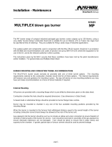
Figure 2-3_Gas Train Detached for Burner Removal
e) Remove mounting screws from the manifold
mounting brackets. Remove the manifold/orifice
assembly from the burners (FIG. 2-3).
f) Remove the mounting screws from each burner and
slide the burner out toward the front of the pool heater.
Use caution to prevent damage to burners, burner
gaskets, refractory, spark igniter, flame sense, or wiring.
g) Remove soot from burners with a stiff bristle brush.
Dirt may be removed from the burner ports by
rinsing the burner thoroughly with water. Drain and
dry burners before re-installing. Damaged burners
must be replaced.
A pool heater installed in a dust or dirt contaminated
atmosphere will require cleaning of the burners on a 3 to 6
month schedule or more often, based on severity of
contamination. Contaminants can be drawn in with the
combustion air. Non-combustible particulate matter such as
dust, dirt, concrete dust, or drywall dust can block burner ports
and cause non-warrantable failure. Use extreme care when
operating a pool heater during new construction. The burners
will probably require a thorough cleaning before the pool heater
is placed in service.
Service Manual
17
2
Maintenance
(continued)
Do not wet the pool heater’s refractory.
NOTICE
2. Combustion Air Fan: The combustion air fan should
be checked every 6 months or each season of operation.
Clean fan as required when installed in a dust or dirt
contaminated location.
3. Water Circulating Pump: Ensure that the filter system
pump is providing adequate flow to the pool heater.
Backwash and clean filter as required to maintain
proper flow.
4. Keep the pool heater area clear and free from
combustible materials, gasoline, and other flammable
vapors and liquids.
5. Check frequently to be sure the flow of combustion and
ventilation air to the pool heater is not obstructed.
6. This pool heater uses a transformer to supply a low
voltage control circuit. The voltage on the secondary
side should be 24 to 28 VAC when measured with a
voltmeter.
7. Direct Spark Igniter Replacement: The direct spark
igniter can be replaced with an OEM igniter available
from your dealer.
a) Turn off main power to the pool heater.
b) Turn off main manual gas shutoff to the pool heater.
c) Remove the front outer jacket panels to access the
front chamber.
d) Disconnect the rajah connector from the igniter
(FIG. 2-5).
e) Remove the igniter retaining screws and slide the
igniter out of the combustion chamber.
f) Install the new igniter into the combustion chamber.
g) Reattach the rajah connector to the new igniter.
h) Reassemble in reverse order.
Figure 2-4_Exploded View of the Heater
Heat exchanger cleaning
h) While burners are removed, check the heat
exchanger surface for sooting. If soot is present,
heat exchanger must be cleaned and problem
corrected. Proceed as follows:
i) Disconnect the connector from the combustion fan.
j) Disconnect the spark ignition wire from the back
of the control module.
k) Disconnect the flame rod wire from the back of
the control module.
l) Remove the screws around the combustion
chamber door. Remove the combustion chamber
door from the unit.
m) Remove soot from the heat exchanger with a stiff
bristle brush. Use a vacuum to remove loose soot
from surfaces and inner chamber.
n) Ensure that all burner ports are cleaned to remove
any soot. See the Burner Cleaning Procedure
section on page 16 of this manual.
o) Carefully reinstall the “V” baffles if removed from
the pool heater.
p) Reinstallation is the reverse of the installation
procedure. Use new gasket material to ensure a
proper air seal.
q) Reassemble all gas piping. Test for gas leaks.
r) Reassemble outer jacket panels.
s) Cycle the pool heater and check for proper
operation.
Figure 2-5_Igniter Replacement
18
Service Manual
Combustion Air Shutter Adjustment
This pool heater uses a fan assisted combustion process. The fan
air shutter is factory preset and should not need adjusting in
most cases. If adjustment is required, the fan air shutter may be
manually adjusted to a dimension specified for each model (see
Table 2B).
Follow the steps below to adjust the fan air shutter if the pool
heater does not function properly or a continuous low air
condition is observed:
1. Check for proper installation and draft in the venting
system. Correct as required.
2. Remove the upper left access door (FIG. 2-6).
3. Turn the power switch to the “OFF” position.
4. Turn the gas valve switch to the “OFF” position.
5. Use a ruler to measure the distance from the base of
the fan to the end of the air shutter (FIG. 2-7).
Compare this distance to the specified A dimension
for the pool heater in Table 2B.
6. Turn all gas valve knobs and the manual gas cock to the
“OFF” position.
7. Locate the air pressure switch located on the left side
panel. Trace the hose from the air pressure switch to the
chamber pressure barb located in the top of the upper
chamber. Remove the hose from the chamber pressure
barb and connect the hose from the manometer or
magnahelic to this barb to measure the air pressure in
the front chamber.
8. Turn the power switch to the “ON” position.
9. Set the thermostat to call for heat. The fan will start.
10. While the combustion air fan is running for the prepurge
cycle and the pressure in the front chamber stabilizes,
record the pressure in the front chamber. This pressure
will be used to calculate the net manifold pressure.
11. Turn the power switch to the “OFF” position.
12. Remove the manometer or magnahelic hose from the front
chamber barb and reinstall the hose from the air pressure
switch to the barb.
13. If the pressure switch still exhibits failures, check the
differential air pressure measurement.
Figure 2-6_Combustion Air Fan Location
2
Maintenance
"A"
Figure 2-7_Combustion Air Fan with Air Shutter “A”
Dimension
TABLE - 2B
AIR SHUTTER
ADJUSTMENT OPENING
Model
A Dimension
Opening
Chamber
Pressure
ER152 1 1/4" 1.4"
ER202 1 1/4" 1.4"
ER252 1 3/8" 1.4"
ER302 1 9/16" 1.4"
ER402 1 3/4" 1.4"
Service Manual
19
Gas train and controls
)
Figure 2-9_Gas Train Drawing
The gas train and controls assembly
provided on this pool heater have been
tested under the applicable American
National Standard to meet minimum safety
and performance criteria such as safe
lighting, combustion, and safety shutdown
operation.
NOTICE
2
Maintenance
(continued)
Differential air pressure measurement
The differential air pressure measurement can be checked
with a slack tube manometer (FIG. 2-8). Disconnect the
two tubes from the air pressure switch and connect one to
each side of a manometer. Turn on the pool heater and
allow the combustion air fan to operate. The observed
pressure reading on the manometer should correspond to
the range shown in Table 2C - Differential Air Chart if the
air shutter is properly adjusted. The differential pressure
varies based on air density at elevation.
TABLE - 2C
DIFFERENTIAL AIR CHART
Differential Air Elevation
1.65" - 1.80" w.c. 0 - 4,000'
1.40" - 1.60" w.c. 4,000' - 8,000'
1.20" - 1.40" w.c. 8,000' - 12,000'
Figure 2-8_Air Shutter Pressure Measurement
20
Service Manual
Facts about water chemistry
Factors which affect pool and spa water and, more importantly,
the efficiency of your new pool/spa heater are:
1. Proper Filtration
2. Proper Circulation
3. Disinfection and Oxidation
4. pH Control and Total Alkalinity
5. Algae Control
The water chemistry of your pool or spa changes daily due to
natural evaporation of the water and the addition of chemicals.
Chemicals are used to sanitize and control algae growth in the
pool. Their addition must be carefully monitored. If there is an
imbalance in the pool water chemistry, the minerals in the pool
water will precipitate out and collect in the pool, filter system
and the pool heater. The accumulation of minerals or scale in
the pool heater due to a chemical imbalance will cause a non-
warrantable failure of the heat exchanger and its components.
pH is the most important factor in maintaining proper balance
in your pool/spa water. pH is the measurement of the acidity or
alkalinity of water. The chart in FIG. 2-10 shows the ideal pH
range and what can happen when the pH increases or decreases
from the ideal of 7.2 to 7.8.
Figure 2-10_pH Scale
If the pH becomes too high, it lowers the ability of chlorine to
destroy bacteria and algae, water can become cloudy, filter
elements may become blocked, and scale formation will occur in
the pool and heat exchanger. If the pH becomes too low the
water becomes acid. You can have eye burn and skin irritation,
etching of the plaster, corrosion of metal fixtures, and the
resulting stains on the plaster, degradation of sand and gravel
filters, and corrosion of the copper tubes in the heat exchanger.
Damage to the pool heater due to improper pH is
non-warrantable.
TABLE - 2D
RECOMMENDED POOL CHEMISTRY LEVELS
Test Recommended Level
Correct pH 7.2 - 7.8
Chlorine Residual 1.0 - 5.0 ppm
Total Alkalinity 80 - 120 ppm
Calcium Hardness 175 - 350 ppm
Chlorine residual is the chlorine remaining in the pool water
after it is consumed in the process of destroying bacteria, algae,
and other oxidizable materials.
Total alkalinity is the measurement of the total amount of
alkaline chemicals in the water. Alkalinity controls pH. Sodium
bicarbonate is used to raise total alkalinity.
Calcium hardness can be raised by the addition of calcium
chloride, and lowered by the addition of Tri-sodium Phosphate
or its equivalent.
The corrosive level of pool water can also be measured by the
Langlier Saturation Index. This index is calculated by a formula
which uses operating temperatures, total alkalinity, pH, calcium
hardness and total dissolved solids. The optimum Saturation
Index value is zero. A negative value indicates a corrosive
condition. Your pool/spa dealer can provide additional data and
equipment to make this measurement if a problem exists.
2
Maintenance
We recommend using a four-way test kit to monitor the
following levels (see Table 2D) to ensure proper operation of
your pool heater:
  • Page 1 1
  • Page 2 2
  • Page 3 3
  • Page 4 4
  • Page 5 5
  • Page 6 6
  • Page 7 7
  • Page 8 8
  • Page 9 9
  • Page 10 10
  • Page 11 11
  • Page 12 12
  • Page 13 13
  • Page 14 14
  • Page 15 15
  • Page 16 16
  • Page 17 17
  • Page 18 18
  • Page 19 19
  • Page 20 20
  • Page 21 21
  • Page 22 22
  • Page 23 23
  • Page 24 24
  • Page 25 25
  • Page 26 26
  • Page 27 27
  • Page 28 28
  • Page 29 29
  • Page 30 30
  • Page 31 31
  • Page 32 32

Lochinvar EnergyRite ER152 User manual

Category
Above ground pool accessories
Type
User manual

Ask a question and I''ll find the answer in the document

Finding information in a document is now easier with AI