15
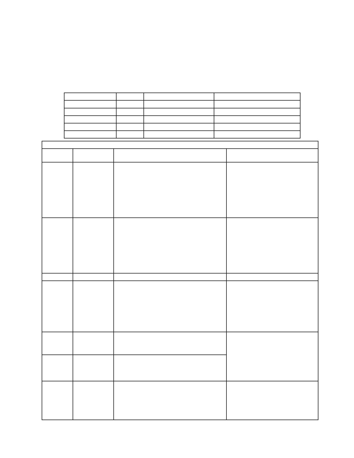
3. LED Lights and Alarm Safeties Chart
With proper power supply, the "POWER OK" LED energizes and remains on. LEDs
1 through 5 energize as the unit cycles through the sequence of operation. If an error
occurs, the alarm code and cabinet temperature are displayed in 2-second intervals and
an alarm sounds. To temporarily reset alarm, press the display board "RESET" button. To
reset and clear the control board memory of an alarm, press the control board "ALARM
RESET" button. See the table below for a description of alarms and reset options.
Sequence Steps LEDs Energized Components Notes
Start - EvapFM LED 3 off when EvapFM energized.
Cool Down 4 and 5 EvapFM, Comp, and ConFM At startup 2.5 minute Comp delay.
Cool Down Achieved - EvapFM 2.5 minute minimum off time.
Defrost 5 EvapFM, ConFM -
Door Open 2 Cabinet Light (solid door) -
Alarm Signals
Alarm
Code
No. of Beeps
(every 10 sec.) Problem Reset Options
E1 3
High Temperature Alarm
Cabinet temperature has remained above
setpoint by 10°F (5.6°C) for more than 2 hours.
Press the display board "RESET"
button. If temperature has returned to
setpoint range, alarm stops and "E1"
clears.
If temperature is not back in range,
pressing the display board "RESET"
button temporarily silences the alarm
for 5 minutes. "E1" continues to ash.
E2 4
Low Temperature Alarm
Cabinet temperature has remained below
setpoint by 8°F (4.4°C) for more than 1 hour.
Press the display board "RESET"
button. If temperature has returned to
setpoint range, alarm stops and "E2"
clears.
If the temperature is not back in range,
pressing the display board "RESET"
button temporarily silences the alarm
for 5 minutes. "E2" continues to ash.
E3 5 N/A [Freezer Only] Defrost longer than 1 hour. N/A
E4 6
High Pressure Alarm
Compressor discharge pressure is outside
normal operating range. Pressure switch has
been triggered 3 or more times in 1 hour.
If switch trips 5 times in 1 hour, compressor
stops and will not restart.
After 5 high pressure switch trips, the
alarm can be silenced for 1 hour by
pressing the display board "RESET"
button.
Service Tech: Reset by pressing the
control board "ALARM RESET" button.
E6 8
High Voltage (140VAC±5% or less) "POWER OK" LED turns off if voltage
protection operates. The voltage
safeties automatically reset when
voltage is corrected.
Press the display board "RESET"
button to temporarily silence the alarm
for 5 minutes.
E7 9
Low Voltage (90VAC±5% or less)
E8 Constant
Cabinet Thermistor
During alarm, unit operates in cabinet
thermistor fail mode.
Cabinet Thermistor Fail Mode: Unit on
5 minutes, off 5 minutes. This continues until
thermistor is replaced.
After replacing thermistor, alarm
resets.
During alarm, press the display board
"RESET" button to silence alarm for
5 minutes.


