ESAB Aristodrive 4-30 & 4-48HD Wire Feeder User manual
- Category
- Welding System
- Type
- User manual

ARISTODRIVE 4-30 & 4-48HD
WIRE FEEDER
0558003750 10 / 2003
INSTRUCTION MANUAL
ESAB ITEM NO. 0558003275, AristoDrive 4-48
ESAB ITEM NO. 0558003276, AristoDrive 4-30
Revision B

2
BE SURE THIS INFORMATION REACHES THE OPERATOR
These INSTRUCTIONS are for experienced operators. If you are not fully familiar with
the principles of operation and safe practices for arc welding and cutting equipment,
we urge you to read our booklet, "Precautions and Safe Practices for Arc Welding,
Cutting, and Gouging," Form 52-529. Do NOT permit untrained persons to install,
operate, or maintain this equipment. Do NOT attempt to install or operate this
equipment until you have read and fully understand these instructions. If you do not
fully understand these instructions, contact your supplier for further information. Be
sure to read the Safety Precautions before installing or operating this equipment.
Copies of this manual can be obtained by any of the following;
Contacting your local ESAB supplier.
Downloading a copy from the ESAB web site at
www.esabna.com
Sending a written request to
ESAB WELDING & CUTTING PRODUCTS
ATTN: LITERATURE DEPT.
411 S EBENEZER ROAD
FLORENCE SC 29501
USER RESPONSIBILITY
This equipment will perform in conformity with the description thereof contained in this manual and
accompanying labels and/or inserts when installed, operated, maintained and repaired in accordance
with the instructions provided. This equipment must be checked periodically. Malfunctioning or
poorly maintained equipment should not be used. Parts that are broken, missing, worn, distorted
or contaminated should be replaced immediately. Should such repair or replacement become
necessary, the manufacturer recommends that a telephone or written request for service advice
be made to the Authorized Distributor from whom it was purchased.
This equipment or any of its parts should not be altered without the prior written approval of the
manufacturer. The user of this equipment shall have the sole responsibility for any malfunction
which results from improper use, faulty maintenance, damage, improper repair or alteration by
anyone other than the manufacturer or a service facility designated by the manufacturer.

3
SECTION TITLE PAGE
PARAGRAPH
1 DESCRIPTION ......................................................................................................................11
2 INSTALLATION .....................................................................................................................19
3 OPERATION .........................................................................................................................23
4 TROUBLESHOOTING ..........................................................................................................25
Schematic .............................................................................................................26
Wiring Diagram .....................................................................................................27
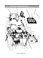
5 REPLACEMENT PARTS .......................................................................................................29
AristoDrive 4-30 ....................................................................................................30
AristoDrive 4-48 ....................................................................................................39
TABLE OF CONTENTS
Page is loading ...

5
WARNING:
These Safety Precautions are for
your protection. They summarize precaution-
ary information from the references listed in
Additional Safety Information section. Before performing
any installation or operating procedures, be sure to read and
follow the safety precautions listed below as well as all other
manuals, material safety data sheets, labels, etc. Failure to
observe Safety Precautions can result in injury or death.
PROTECT YOURSELF AND OTHERS
--
Some welding, cutting, and gouging
processes are noisy and require ear
protection. The arc, like the sun, emits
ultraviolet (UV) and other radiation and
can injure skin and eyes. Hot metal can cause burns.
Training in the proper use of the processes and equip-
ment is essential to prevent accidents. Therefore:
1. Always wear safety glasses with side shields in any work
area, even if welding helmets, face shields, and goggles
are also required.
2. Use a face shield fitted with the correct filter and cover
plates to protect your eyes, face, neck, and ears from
sparks and rays of the arc when operating or observing
operations. Warn bystanders not to watch the arc and not
to expose themselves to the rays of the electric-arc or hot
metal.
3. Wear flameproof gauntlet type gloves, heavy long-sleeve
shirt, cuffless trousers, high-topped shoes, and a weld-
ing helmet or cap for hair protection, to protect against
arc rays and hot sparks or hot metal. A flameproof apron
may also be desirable as protection against radiated
heat and sparks.
4. Hot sparks or metal can lodge in rolled up sleeves,
trouser cuffs, or pockets. Sleeves and collars should be
kept buttoned, and open pockets eliminated from the
front of clothing
5. Protect other personnel from arc rays and hot sparks with
a suitable non-flammable partition or curtains.
6. Use goggles over safety glasses when chipping slag or
grinding. Chipped slag may be hot and can fly far.
Bystanders should also wear goggles over
safety glasses.
FIRES AND EXPLOSIONS -- Heat from
flames and arcs can start fires. Hot slag
or sparks can also cause fires and ex-
plosions. Therefore:
1. Remove all combustible materials well away from the
work area or cover the materials with a protective non-
flammable covering. Combustible materials include wood,
cloth, sawdust, liquid and gas fuels, solvents, paints and
coatings, paper, etc.
2. Hot sparks or hot metal can fall through cracks or
crevices in floors or wall openings and cause a hidden
smoldering fire or fires on the floor below. Make certain
that such openings are protected from hot sparks and
metal.“
3. Do not weld, cut or perform other hot work until the
workpiece has been completely cleaned so that there are
no substances on the workpiece which might produce
flammable or toxic vapors. Do not do hot work on closed
containers. They may explode.
4. Have fire extinguishing equipment handy for instant use,
such as a garden hose, water pail, sand bucket, or
portable fire extinguisher. Be sure you are trained in its
use.
5. Do not use equipment beyond its ratings. For example,
overloaded welding cable can overheat and create a fire
hazard.
6. After completing operations, inspect the work area to
make certain there are no hot sparks or hot metal which
could cause a later fire. Use fire watchers when necessary.
7. For additional information, refer to NFPA Standard 51B,
"Fire Prevention in Use of Cutting and Welding Pro-
cesses", available from the National Fire Protection Asso-
ciation, Batterymarch Park, Quincy, MA 02269.
ELECTRICAL SHOCK -- Contact with live
electrical parts and ground can cause
severe injury or death. DO NOT use AC
welding current in damp areas, if move-
ment is confined, or if there is danger of
falling.
1. Be sure the power source frame (chassis) is connected
to the ground system of the input power.
2. Connect the workpiece to a good electrical ground.
3. Connect the work cable to the workpiece. A poor or
missing connection can expose you or others to a fatal
shock.
4. Use well-maintained equipment. Replace worn or dam-
aged cables.
5. Keep everything dry, including clothing, work area, cables,
torch/electrode holder, and power source.
6. Make sure that all parts of your body are insulated from
work
and from ground.
7. Do not stand directly on metal or the earth while working
in tight quarters or a damp area; stand on dry boards or
an insulating platform and wear rubber-soled shoes.
8. Put on dry, hole-free gloves before turning on the power.
9. Turn off the power before removing your gloves.
10. Refer to ANSI/ASC Standard Z49.1 (listed on next page)
for specific grounding recommendations. Do not mistake
the work lead for a ground cable.
ELECTRIC AND MAGNETIC FIELDS —
May be dangerous. Electric current flow-
ing through any conductor causes lo-
calized Electric and Magnetic Fields
(EMF). Welding and cutting current cre-
ates EMF around welding cables and
welding machines. Therefore:
1. Welders having pacemakers should consult their physi-
cian before welding. EMF may interfere with some pace-
makers.
2. Exposure to EMF may have other health effects which are
unknown.
3. Welders should use the following procedures to minimize
exposure to EMF:
A. Route the electrode and work cables together. Secure
them with tape when possible.
B. Never coil the torch or work cable around your body.
C. Do not place your body between the torch and work
cables. Route cables on the same side of your body.
D. Connect the work cable to the workpiece as close as
possible to the area being welded.
E. Keep welding power source and cables as far away
from your body as possible.
SAFETY PRECAUTIONS

6
FUMES AND GASES -- Fumes and
gases, can cause discomfort or harm,
particularly in confined spaces. Do
not breathe fumes and gases. Shield-
ing gases can cause asphyxiation.
Therefore:
1. Always provide adequate ventilation in the work area by
natural or mechanical means. Do not weld, cut, or gouge
on materials such as galvanized steel, stainless steel,
copper, zinc, lead, beryllium, or cadmium unless positive
mechanical ventilation is provided. Do not breathe fumes
from these materials.
2. Do not operate near degreasing and spraying opera-
tions. The heat or arc rays can react with chlorinated
hydrocarbon vapors to form phosgene, a highly toxic
gas, and other irritant gases.
3. If you develop momentary eye, nose, or throat irritation
while operating, this is an indication that ventilation is not
adequate. Stop work and take necessary steps to im-
prove ventilation in the work area. Do not continue to
operate if physical discomfort persists.
4. Refer to ANSI/ASC Standard Z49.1 (see listing below)
for specific ventilation recommendations.
5. WARNING: This product, when used for welding or
cutting, produces fumes or gases which
contain chemicals known to the State of
California to cause birth defects and, in
some cases, cancer. (California Health &
Safety Code
§25249.5 et seq.)
CYLINDER HANDLING -- Cylinders, if
mishandled, can rupture and violently
release gas. Sudden rupture of cylin-
der, valve, or relief device can injure or
kill. Therefore:
1. Use the proper gas for the process and use the proper
pressure reducing regulator designed to operate from
the compressed gas cylinder. Do not use adaptors.
Maintain hoses and fittings in good condition. Follow
manufacturer's operating instructions for mounting regu-
lator to a compressed gas cylinder.
2. Always secure cylinders in an upright position by chain or
strap to suitable hand trucks, undercarriages, benches,
walls, post, or racks. Never secure cylinders to work
tables or fixtures where they may become part of an
electrical circuit.
3. When not in use, keep cylinder valves closed. Have valve
protection cap in place if regulator is not connected.
Secure and move cylinders by using suitable hand trucks.
Avoid rough handling of cylinders.
4. Locate cylinders away from heat, sparks, and flames.
Never strike an arc on a cylinder.
5. For additional information, refer to CGA Standard P-1,
"Precautions for Safe Handling of Compressed Gases in
Cylinders", which is available from Compressed Gas
Association, 1235 Jefferson Davis Highway, Arlington,
VA 22202.
EQUIPMENT MAINTENANCE -- Faulty or
improperly maintained equipment can
cause injury or death. Therefore:
1. Always have qualified personnel perform the installation,
troubleshooting, and maintenance work. Do not perform
any electrical work unless you are qualified to perform
such work.
2. Before performing any maintenance work inside a power
source, disconnect the power source from the incoming
electrical power.
3. Maintain cables, grounding wire, connections, power
cord, and power supply in safe working order. Do not
operate any equipment in faulty condition.
4. Do not abuse any equipment or accessories. Keep
equipment away from heat sources such as furnaces,
wet conditions such as water puddles, oil or grease,
corrosive atmospheres and inclement weather.
5. Keep all safety devices and cabinet covers in position
and in good repair.
6. Use equipment only for its intended purpose. Do not
modify it in any manner.
ADDITIONAL SAFETY INFORMATION -- For
more information on safe practices for elec-
tric arc welding and cutting equipment, ask
your supplier for a copy of "Precautions and
Safe Practices for Arc Welding, Cutting and
Gouging", Form 52-529.
The following publications, which are available from the
American Welding Society, 550 N.W. LeJuene Road, Mi-
ami, FL 33126, are recommended to you:
1. ANSI/ASC Z49.1 - "Safety in Welding and Cutting"
2. AWS C5.1 - "Recommended Practices for Plasma Arc
Welding"
3. AWS C5.2 - "Recommended Practices for Plasma Arc
Cutting"
4. AWS C5.3 - "Recommended Practices for Air Carbon Arc
Gouging and Cutting"
5. AWS C5.5 - "Recommended Practices for Gas Tungsten
Arc Welding“
6. AWS C5.6 - "Recommended Practices for Gas Metal Arc
Welding"“
7. AWS SP - "Safe Practices" - Reprint, Welding Handbook.
8. ANSI/AWS F4.1, "Recommended Safe Practices for
Welding and Cutting of Containers That Have Held
Hazardous Substances."
MEANING OF SYMBOLS - As used through-
out this manual: Means Attention! Be Alert!
Your safety is involved.
Means immediate hazards which, if
not avoided, will result in immediate,
serious personal injury or loss of life.
Means potential hazards which could
result in personal injury or loss of life.
Means hazards which could result in
minor personal injury.
SAFETY PRECAUTIONS
Page is loading ...
Page is loading ...
Page is loading ...
Page is loading ...

11
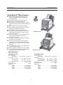
AristoDrive 4
TM
-Wire Feeders
■
Modular MMC panel for easy function and
feature upgradability (MMC=Man/Machine
Communications) .
■
Use with AristoPower-460 Power Source
■
Heavy duty compact wire feed motor.
■
Quick release 4-roll drive assembly; no read-
justment of pressure required when rethreading
wire.
■
Quick release “No Tools” feed roll system.
■
Driven upper and lower feed rolls for positive
feed force and maximum wire grip.
■
Presettable arc voltage and wire speed
■
All control circuits incorporated on one solid-
state printed circuit board, mounted for easy
access and removal.
■
Slow run-in button sets the wire feed speed to
1/2 the preset until the arc is struck for
smoother arc starting.
■
Jog button for wire inching without energizing
the power source contactor.
■
Anti-stick wire burnback control for precise
adjustment of amount of wire burnback after
wire feed stops, to eliminate freezing of wire in
weld pool.
■
Low voltage circuit (12V) for gun trigger switch,
to assure operator safety.
■
NAS (#4 Tweco) gun adapter factory installed.
■
“Sure Start” wire conditioning to eliminate wire
balling and ensure good arc starting
Specifications:
AristoDrive 4-30
Wire Feed Range:
Speed Range ........ 30-999 in/min (.8 - 25 m/min)
Wire Sizes:
Hard (V-Groove) ...... .023 - 1/16 in.(.6-1.6mm)
Cored (Knurled) ....... .035 - 5/64 in.(.9-2.0mm)
Soft (U-Groove) ....... .035 - 1/16 in.(.9-1.6mm)
Input power ................................................ 42 Vac / 60hz.
Drive Roll Diameter ................................................. 30mm
Dimensions:
Length ....................................... 22.5 in.(572mm)
Width......................................... 10.5 in.(268mm)
Height ....................................... 16.5 in.(419mm)
Weight........................................ 45-lbs.(20.5Kg)
AristoDrive 4-48
Wire Feed Range:
Speed Range ..... 30-800 in/min (.8 - 20.5 m/min)
Wire Sizes:
Hard (V-Groove) .... .035 - 1/16 in.(.9 - 1.6mm)
Tubular (Knurled) .. .035 - 1/8 in. (.9 - 3.2mm)
Soft (U-Groove) ..... .045 - 3/32 in.(.9 - 2.4mm)
Input Power ................................................ 42 Vac / 60hz.
Drive Roll Diameter ................................................. 48mm
Dimensions:
Length .......................................... 23 in.(584mm)
Width......................................... 14.5 in.(368mm)
Height ....................................... 16.5 in.(419mm)
Weight............................................53 lbs.(24Kg)
AristoDrive 4-30
AristoDrive 4-48
SECTION 1 DESCRIPTION

12
Trigger Leads, ESAB Style
Trigger Lead, GunMaster 250 ......................... 0558001815
Trigger Lead, GunMaster 400 ...............................2075216
Options & Accessories
AristoDrive 4
Hanging Bail .................................................... 0558003047
Handle Kit ....................................................... 0558002356
Wheel Kit ................................................................... 34324
Swivel Post ................................................................ 36172
Marathon Pack Inlet Guide ............................. 0558002519
Requires ............................................................... 899F50
Counterbalance Mini-Boom ............................ 0458705881
Reel Assembly .......................................................... 34323
Spool Cover .................................................... 0558003047
Control Cable, 6.5ft.(2m) ................................. 0456527880
Control Cable, 260ft. (8m) ............................... 0456527881
Control Cable, 52ft. (16m) ............................... 0456527882
Control Cable, 82ft. (25m) ............................... 0456527883
Control Cable, 114ft. (35m) ............................. 0456527884
Marathon Pack
Inlet Guide
Hanging bail
Handle
Control Cable
MMA-6 MMC (Man/Machine Communications)
Easy to set weld parameters for MIG, MIG Pulse, Stick or Gouging.
Choose synergic weld parameters from of 107 possibilities. Set
the wire feed speed and weld!
Internal Memory stores up to 10 different weld parameter set-
ups. Recall parameters with a simple push of a button.
Programmable soft keys allow direct access to flexible functions,
such as hot start, crater fill, 2/4 stroke trigger, wire inch, gas purge,
etc.
Large display gives real time voltage, current, and wire feed speed
read-outs.
Preset inductance, gas pre & post flow, inch or metric units, auto
weld schedule select, arc force, burnback and more. Update and
change weld data using optional ESAT software for maximum
flexibility.
SECTION 1 DESCRIPTION

13
1.0 SAFETY
Before the AristoDrive 4-30 or 4-48 wire feeder is put into operation, the safety
section at the front of this manual should be read completely. This will help
avoid possible injury due to misuse or improper installation.
The definitions relating to the:
safety notations are described at the end of the Safety Section in the front of this
manual — read them and their specific text references carefully.
1.1 DESCRIPTION AND SPECIFICATIONS
The AristoDrive 4-30 & 4-48 are heavy duty 4 roll drive 42 vac wire feeders
with the ability to meet immediate and long term welding requirements of any
weld shop. It's "Modular Design" technology permits simplicity and flexibility
without unnecessary configuration and installation complexity. The innovative
and "easy to use" MA-6 AristoDrive control panel (MMC or Man/Machine Com-
munications) simplifies the functionality and features selection of the welding
system. The drive stand gears are totally enclosed for safety, dependable and
reliable operation.
The AristoDrive 4-48 wire feeder will handle the most demanding welding ap-
plications using short arc, spray and pulsed spray arc Mig (GMAW, GMAW-P
& MCAW) welding or cored wire (FCAW ) welding using the AristoPower 460
power source.
A. FEATURES:
• Modular MMC (Man/Machine Communications) panel for easy function
and feature selection
• Heavy duty compact wire feed motor
• AristoDrive 4-48 has a heavy duty drive stand and large 48 mm drive rolls
• AristoDrive 4-30 has a heavy duty drive stand with 30mm rolls.
• Quick release 4-roll drive assembly; no readjustment of pressure required
when rethreading wire.
• Quick change “No Tools” feed roll system
• Driven upper and lower drive rolls for positive feed force and maximum
wire grip.
• All control circuits incorporated on one solid-state printed circuit board,
mounted for easy access and removal.
• Gas purge switch for shield gas flowrate preset.
• Slow run-in panel button sets the wire feed speed at 1/2 the preset until
the arc is struck for smoother arc starting.
• Jog panel button for wire inching without energizing power source contac-
tor.
• 4-stroke, Hot Start and Craterfill panel buttons for easy feature selection.
• Low voltage circuit (12v) for gun trigger switch, to assure operator safety.
• NAS (#4 Tweco) gun adapter
• All cable and hose connections are quickly detachable.
SECTION 1 DESCRIPTION

14
B. Specifications AristoDrive 4-30 & AristoDrive 4-48
(See page 10)
C. Modular MMC System
Introduction
The interchangeable control panels (MMC) are available in 4 different models
depending on the needs of the welding operator and the welding application.
The panels are designed for easily removal and replacement. The following
describes the functions and capability of each MMC panel.
MA-6 MMC MIG/STICK PANEL
The MA-6 MMC panel is a simple, intuitive yet feature rich control panel that
will meet the weld requirements of most Mig, Stick and Arc Gouging applica-
tions. The flow chart below summarizes the features available.
SECTION 1 DESCRIPTION

15
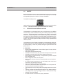
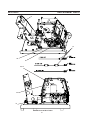
D. Front Panel Components
1. MA-6 MIG/STICK/GOUGING MMC PANEL
2. Power On/Off Switch
Controls the 42 vac power from the AristoPower 460 power source.
A two prong “twist to lock” receptacle used to connect the Mig gun
trigger circuit to the wire feeder.
3. NAS (#4 Tweco) Power Pin Mig gun connection
E. Rear Panel:
1. Control Cable Receptacle
Receptacle that accepts the 19 pin control interconnect cable between
the wire feeder and power source.
2. Shield Gas Connection
Connect the shielding gas hose from the regulator/flowmeter to this
fitting.
3. Circuit Breaker
Prevents damage to the Main control PC board caused by excessive
line current.
4. Power Connection Block
Insulated connection point for the welding cables from the secondary
side of the welding power source.
1.2 RECOMMENDED EQUIPMENT AND ACCESSORIES
A. Control Cable Assembly:
For connection of the AristoDrive 4-48 to ESAB power sources with a
12-pin receptacle, the following control cable assemblies are available:
6-foot (2 m) - 0456 527 880
25-foot (8 m) - 0456 527 881
50-foot (16 m) - 0456 527 882
80-foot (25 m) - 0456 527 883
C. Mig Welding Guns:
Gun Master 250 Gas Cooled
Gun Master 400 Gas Cooled
D. Mig Gun Adapters
Only Tweco #4 is supported
E. Feed Rolls and Outlet Guides:
The appropriate feed roll, outlet guide and center guide is required for
optimum wire feeding. See Table 2-1 & 2-2.
F. Shielding Gas Regulator/Flowmeter:
R-33 FM 580 (Argon) - P/N 21557
R-33 FM 360 (CO2) - P/N 21558
R-5007 Argon/Helium/Nitrogen - P/N 998124
R-5008 CO
2
- P/N 998125.
G. Gas Hoses:
Argon/Helium, Nitrogen - P/N 40V77 (12-1/2 ft.) or P/N 34V38 (25 ft.)
Heavy Duty - P/N 19416 (12-1/2 ft.)* or P/N 19415 (25 ft.)*
* Must be used for CO
2
and can also be used for Argon/Helium/Nitrogen.
SECTION 1 DESCRIPTION

16
MIG TORCH
CONNECTOR
RECEPTACLE
REMOTE
RECEPTACLE
POWER "ON/OFF"
SWITCH
WIRE FEED
SPEED AND
VOLTAGE*
MIG TORCH
TRIGGER
RECEPTACLE
MODULAR MMI
(MAN/MACHINE INTERFACE)
PANEL
SPOOL/REEL
SPINDLE POST
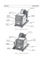
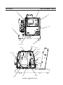
Figure 1-2. AristoDrive 4-48 Wire Feeder
Figure 1-1. AristoDrive 4-30 Wire Feeder
MIG TORCH
CONNECTOR
RECEPTACLE
REMOTE
RECEPTACLE
POWER "ON/OFF"
SWITCH
WIRE FEED
SPEED AND
VOLTAGE*
MIG TORCH
TRIGGER
RECEPTACLE
MODULAR MMI
(MAN/MACHINE INTERFACE)
PANEL
SPOOL/REEL
SPINDLE POST
HEAVY DUTY
48mm ROLL
DRIVE STAND
HEAVY DUTY
30mm ROLL
ENCLOSED
DRIVE STAND
SECTION 1 DESCRIPTION

17
H. OPTIONAL ACCESSORIES
1. Lifting Bracket - Hanging Bail (P/N 0558003047):
Mounts at the top of the wire feeder spool support. Enables you to
mount the wire feeder overhead on a boom or trolley system.
2. Reel Assembly (P/N 34323):
Reel slips over spindle to allow use of coiled wire.
3. Swivel Post (P/N 36172):
Installs on power sources such as ESAB 353cv, 453cv MultiPower
460 and 460 Pulse, or 653cvcc and allows the wire feeder to swivel
freely.
4. Swivel Post w/Mounting Bracket (P/N 34075):
Attaches to inverter cart (P/N 31700) or other flat mounting surface
and allows the feeder to swivel freely
5. Handle Kit (P/N 0558002356)
Includes handle with rubber grip and mounting hardware.
6. Wheel Kit (P/N 34324))
Makes it easy to roll wire feeder around job site Cart includes base,
front swivel caster wheels, rear caster wheels and mounting hard-
ware.
7. Spool Enclousure Kit (AristoDrive 4-30 Only P/N 0558002357)
Cover and enclosure provides protection for a 12" spool of wire
against dust and dirt.
8. Counterbalance Mini-Boom (P/N 0458705881)
Mounts to the power source swivel post and reduces wire feeding
problems caused by sharp bends in the gun liner and cables by
keeping the gun cable off the floor. Includes boom and mounting
hardware. (requires Swivel Post - P/N 36172)
9. Marathon Pack Inlet Guide for AristoDrive 4-30 (P/N
0558002354)
Allows the secure connection of a Marathon Pack conduit/liner to
the rear panel of the AristoDrive wire feeder.
Requires Quick Disconnect Adaptor Kit (QAC) ......... P/N 899F50
10. Marathon Pack Inlet Guide for AristoDrive 4-48 (P/N 0558002519)
Allows the secure connection of a Marathon Pack conduit/liner to
the rear panel of the AristoDrive wire feeder.
Requires Quick Disconnect Adaptor Kit (QAC) P/N 899F50
11. Heavy Duty Pressure Spring (P/N - 0558002142)
Recommended for the 4-48 Drivestands using solid wires of 1/16"
diameter and greater.
NOTE
The Counterbalance Mini-Boom cannot be
used with 14" spools ofr 65 lb. coils.
SECTION 1 DESCRIPTION
Page is loading ...

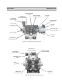
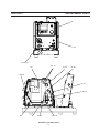
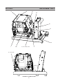
19
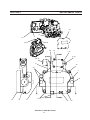
LOWER ROLL
RETAINING KNOB
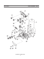
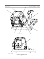
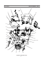
Figure 2-2 AristoDrive 4-48 Drive Stand
FEED ROLL
SHAFT
INLET
GUIDE
PRESSURE
ADJUSTMENT
CENTER GUIDE
LOCKING KNOB
PRESSURE ROLL
ARMS
UPPER ROLL
RETAINING KNOB
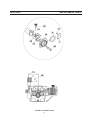
Figure 2-1 AristoDrive 4-30 Drive Stand
PRESSURE
ADJUSTMENT
LOWER ROLL
RETAINING NUTS
INLET GUIDE
LOCKING KNOB
OUTLET GUIDE
LOCKING KNOB
UPPER ROLL
RETAINING KNOB
GUN LOCKING
KNOB
CENTER GUIDE
LOCKING KNOB
CENTER
GUIDE
OUTLET
GUIDE
PRESSURE ROLL
BOGEY
GEAR PIN
AXLE
INLET GUIDE
SECTION 2 INSTALLATION

20
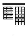
Table 2-2 - AristoDrive 4-48 Feed Roll TableTable 2-1 - AristoDrive 4-30 Feed Roll Table
SECTION 2 INSTALLATION
Wire Size
inch
Wire Size
mm
Part
Number
Solid Wire V Groove
.023-.030 0.8-0.9 0458655001
.035/.040-.045 0.9/1.0-1.2 0458655003
.052-1/16 1.4-1.6 0458655013
Cored Wire Serrated
.035-.045 0.9-1.2 0558002352
.045-.052 1.2-1.4 37319
1/16-5/64 1.6-2.0 37320
Aluminum U Grooved
.035-3/64 0.9-1.2 36860
3/64-1/16 1.2-1.6 36861
Inlet Guide
All 3mm 0455049001
Center Guides
Steel 2mm 0455072001
Steel 3mm 0455072002
Aluminum 2mm 0456615001
Outlet Guides
Steel 1.5mm 0458690880
Steel 2mm 0458690881
Steel 3mm 0458690882
Aluminum 2mm 0458690883
(4 req'd.)
(4 req'd.)
(4 req'd.)
(1 req'd.)
(1 req'd.)
(1 req'd.)
Wire Size
inch
Wire Size
mm
Part
Numbe
r
Solid Wire V Groove
.023
.6mm
0558002235
.030 .8mm 0558002236
.035/.040 .9/1.0mm 0558002237
.045 1.2mm 0558002238
.052
1.4mm
0558002239
1/16" (.062)
1.6mm
0558002240
Cored Wire Serrated
.035
1.0mm
058002227
.045
1.2mm
058002228
.052
1.4mm
058002229
1/16" (.062) 1.6mm 058002230
5/64 (.078) 2.0mm 058002231
3/32 (.093)
2.4mm
058002232
.109
2.8mm
058002233
.125
3.2mm
058002234
Aluminum U Grooved
.030
.8mm
055800243
.035/.040
.9/1.0mm
055800244
3/64 (.047) 1.2mm 055800245
1/16" (.062) 1.6mm 055800247
3/32 (.093)
2.4mm
055800248
Inlet Guide
All
3.5mm
0558002347
HD Brass
3.5mm
0558002517
Center Guides
.023-.045 Steel
1.5mm
0558002223
.052-.062 Steel
2.0mm
0558002224
5/64 (.078) Steel
2.5mm
0558002225
.093-.125 Steel 3.5mm 0558002226
.023-.045 Aluminum 1.5mm 0558002307
.047-.062 Aluminum
2.0mm
0558002308
3/32 (.093) Aluminum
3.5mm
0558002310
Outlet Guides
.023-.045 Steel
1.5mm
0558002215
.052-.062 Steel
2.0mm
0558002216
5/64 (.078) Steel
3.0 mm
0558002217
.093-.125 Steel
3.5mm
0558002218
.023-.045 Aluminum 1.5mm 0558002219
.047-.062 Aluminum 2.0mm 0558002220
3/32 (.093) Aluminum
3.0mm
0558002222
(4 req'd.)
(4 req'd.)
(4 req'd.)
(1 req'd.)
(1 req'd.)
(1 req'd.)
0459052001
0459052003
0459052013

21
2.0 INSTALLATION
After checking to be sure you have all required components and accesso-
ries, proceed as follows:
A. HOSE AND ELECTRICAL CONNECTIONS
1. Connect shielding gas supply hose to the rear panel of the feeder.
2. Connect the 19-pin control cable between the AristoDrive rear panel
and power source wire feeder connection.
3. Connect suitably sized power cable between the power source and
the power block at the rear base of the feeder.
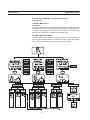
B. CENTER AND OUTLET GUIDES
1. Choose the correct type and size center and outlet guide for the
type of drive stand on the feeder. See Figure 2-1 or 2-2 and Table
2-1 or 2-2.
2. Insert the center guide into the drive stand center support between
the front and rear drive axles. Tighten the locking knob to secure in
place.
3. Insert the outlet guide tapered end first into the front of the Mig gun
adapter and secure with locking knob.
C. MIG GUN CONNECTIONS
Gun Master 250 and 400
1. Connect Mig Gun to feed roll accessory drive by loosening the
locking knob on the drive roll accessory gun adapter and insert the
gun power pin into the gun adaptor then tighten locking knob.
2. Connect the gun trigger twist lock plug into the mating receptacle
on the front panel of the AristoDrive feeder and lock by twisting 1/4
turn.
D. INSTALLING 4-30 FEED ROLL
Lower Feed Rolls
1. Release the tension lever on the pressure roll bogey and flip up to
access the drive rolls
2. Remove the lower feed roll retaining knobs.
3. Separate the feed roll from the gear pin axle and slip the new feed
roll on the gear shaft, engaging the gear pins.
4. Reinstall the feed roll retaining knobs.
Upper Feed Rolls
1. Release the tension lever on the pressure roll bogey and flip up to
access the drive rolls
2. Remove the upper feed roll retaining knobs by turning knob 1/4 turn
and pulling axle straight out.
3. Separate the feed roll from the gear pin axle and slip the new feed
roll on the gear shaft, engaging the gear pins.
4. Reinstall the feed roll retaining knob and axle.
SECTION 2 INSTALLATION

22
E. INSTALLING 4-48 FEED ROLLS
1. Release the tension levers on the pressure roll arms and flip outward
(away from the center of the drive stand) to lift the top rolls from the
bottom rolls.
2. Twist the feed roll retaining knobs so that the flutes align with the axle
pin.
3. Slip the feed roll on the axle and over the axle pins.
4. Twist the retaining knob 1/8 turn to lock the rolls in place.
F. INSTALLING SPOOL OF WIRE (4-48)
1. Remove “S-pin” clip from spindle.
2. Position the spool of wire so that when it is placed on the spindle, wire
will be drawn to the feed roll from the bottom of the spool. The spool
should be held so that the index hole on the spool will engage the pin
on the spindle.
3. Slide the spool onto the spindle until it engages the spindle pin. Lock
in place with the S-pin clip.
4. Loosen the brake screw in the center of the spindle hub, then tighten
it just enough to prevent coasting of the spool when wire is drawn
from it. Too much pressure will load the wire feed motor unnecessar-
ily. Too little pressure will permit the spool to overrun, causing the wire
to come loose and tangle.
5. Thread wire to gun as follows:
a. Round off the free end of the welding wire with a file.
b. Release the tension levers on the pressure roll arm assem-
bly.
c. Thread the wire through the inlet guide, over the feedroll
grooves and into the outlet guide.
d. Close the pressure roll making sure the wire is seated in
both the top and bottom feed roll grooves.
e. Remove nozzle and contact tip from the gun. Turn on the
Power Source using the main power switch. Inch the wire,
using the AristoDrive jog switch, until the wire exits the front
end of gun. Thread the contact tip over the wire and tighten
into the tip adapter. Replace gun nozzle.
6. When wire coils are to be used, raise the spindle assembly to its high-
est mounting position in the spindle post. Mount the wire reel onto the
spindle as though it were a spool (see 1 and 3 above). Remove wing
nuts and cover plate from reel. Remove coil from its package, but do
not remove its binding wires or straps. Slide coil onto reel so that
wire will be drawn from bottom of coil (starting end for a coil is always
the outer end). Replace reel cover plate and wing nuts. Cut off coil tie
wires. Adjust brake screw and thread wire to the gun as covered in 4
and 5 above.
G. ADJUSTING THE PRESSURE ROLL ASSEMBLY
When a new wire size or type installed, set the pressure adjustment as fol-
lows:
1. Unscrew the pressure adjustment knob until the pressure knob is free.
2. Alternately press and release the gun trigger switch while slowly tight-
ening the pressure adjusting knob until the wire begins to feed without
slipping. The pressure applied should be the minimum required to
provide positive, nonslip wire feed. Too little pressure will result in wire
slippage while excessive pressure will scar and deform the wire.
SECTION 2 INSTALLATION

23
3.0 ADJUSTMENTS AND OPERATION
A. CONTROL SETTINGS
1. Turn the AristoDrive POWER switch to the “ON” position then turn on
the AristoPower power source.
2. Set the weld process, wire type, wire size and shielding gas being
used on the MA-6 MMC panel. See the MA-6 Instruction manual for
more details and complete MA-6 operation.
3. Set the wire feed rate by adjusting the WIRE FEED SPEED control
knob on the MMC panel. The wire feed rate controls the weld current
furnished by the CV power source.
B. FEEDING WIRE
If wire has been threaded through gun and contact tip, simply operate the jog
button or cut off wire, as required, so that the wire extends about 1/2 in. be-
yond the end of the gun nozzle.
C. SHIELDING GAS FLOW RATE
Actuate the gas purge button on the MA-6 Panel and set gas flow rate at the
shielding gas regulator-flowmeter to 35 to 40 cfh. Maintain flow for at least 15
seconds to insure adequate purging of gas hose and gun. Preflow/postflow
times can be set under the SETTINGS menu on the MA-6 MMC panel.
D. SLOW INCH BUTTON
Press the SLOW INCH button if a slow run-in of the weld wire is desired. The
wire feed speed will then be at 1/2 the preset wire feed rate when the gun
trigger is pulled until the arc is struck. The wire speed will then increase to the
preset speed for welding. This functions gives smoother arc starting for some
weld applications.
E. MAKING THE WELD
Start to weld by pressing the gun trigger lever. This closes the welding contactor,
and starts gas flow and wire feed. When the welding wire touches the workpiece
an arc will be established. The trigger switch lever must be depressed for the
duration of the weld (unless the trigger latch option has been installed and set
in the trigger latch position). Welding action will be stopped and all services
discontinued when the trigger switch lever is released and returns to its origi-
nal position. If the gun is withdrawn from the workpiece during welding, the arc
will be interrupted, but shielding gas flow and welding wire feed will continue
until the switch lever is released.
SECTION 3 OPERATION

24
3.1 OPERATING SEQUENCE
NORMAL
1 . Close gun trigger switch.
— Gas solenoid opens, weld contactor closes, wire feed motor runs at
preset wire feed speed, or slow inch, whichever has been selected.
2. Release gun trigger switch.
— Wire feed motor de-energized, brake circuit enabled.
— Anti-stick circuit energized.
— Weld contactor opens.
— Burnback circuit times out
(delay determined by setting of Burnback potentiometer).
— Gas solenoid valve closes.
SECTION 3 OPERATION

25
A. MAINTENANCE
If this equipment does not operate properly, stop work immediately and
investigate the cause of the malfunction. Maintenance work must be per-
formed by an experienced person, and electrical work by a trained elec-
trician. Do not permit untrained persons to inspect, clean, or repair this
equipment. Use only recommended replacement parts.
B. GENERAL MAINTENANCE
Little maintenance is required to keep the wire feeder in top operating condi-
tion. It is important, however, that moving parts such as feed and pressure
rolls, wire feed motor, etc., be kept clean and free of dust or dirt. Cleaning is
best accomplished by regularly blowing off these parts with dry compressed
air. This should be done once for every eight hours of operating time, more
often if necessary.
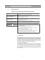
SECTION 4 TROUBLESHOOTING
4.0 TROUBLESHOOTING
Table 4-1 AristoDrive 4-48 Troubleshooting Chart
Nothing works Check if power source is energized
Check if DuraDrive "Power" switch is in the "ON" position
Wire Feeder is "ON", motor does not run,
gas valve and welding power source
contactor do not ener
g
ize
Check CB fuse on DuraDrive Rear Panel
Check weld gun trigger plug connection
Wire feeds, shielding gas flows, but no
p
ower to electrode wire
Check if power source has Open Circuit Voltage
Check if weld cables are connected
Check interconnect cable for continuit
y
or loose connection
Motor runs slowly and/or gas solenoid
vale is "chatterin
g
"
Check for 42 vac input voltage
Welding wire feed cannot be shut OFF
and feeds continuously
Short in welding gun trigger leads.
valve is "chattering"
AristoDrive
AristoDrive
Electrode wire stops of feeds erratically
during welding
Check weld gun trigger connection
Check weld
g
un tri
gg
er switch
Read
j
ust s
p
ool s
p
indle brake and
p
ressure roll tension
Check for the correct size and type drive rolls for the electrode wire being used.
Clean or re
p
lace dirt
y
or worn drive rolls.
Check for incorrect t
yp
e or sized outlet and center
g
uides
Check and/or replace the weld gun contact tip and/or liner if worn or damaged
Remove weld s
p
atter and debris form weld
g
un nozzle and contact ti
p
Have an ESAB Authorized Repair station check the motor drive and control PCB.
or

26
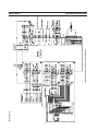
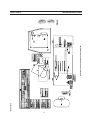
SECTION 4 TROUBLESHOOTING
AristoDrive 4-30 and 4-48 Schematic Diagram
0558003277-A
Page is loading ...
Page is loading ...
Page is loading ...
Page is loading ...
Page is loading ...
Page is loading ...
Page is loading ...
Page is loading ...
Page is loading ...
Page is loading ...
Page is loading ...
Page is loading ...
Page is loading ...
Page is loading ...
Page is loading ...
Page is loading ...
Page is loading ...
Page is loading ...
Page is loading ...
Page is loading ...
Page is loading ...
Page is loading ...
Page is loading ...
Page is loading ...
Page is loading ...
Page is loading ...
-
 1
1
-
 2
2
-
 3
3
-
 4
4
-
 5
5
-
 6
6
-
 7
7
-
 8
8
-
 9
9
-
 10
10
-
 11
11
-
 12
12
-
 13
13
-
 14
14
-
 15
15
-
 16
16
-
 17
17
-
 18
18
-
 19
19
-
 20
20
-
 21
21
-
 22
22
-
 23
23
-
 24
24
-
 25
25
-
 26
26
-
 27
27
-
 28
28
-
 29
29
-
 30
30
-
 31
31
-
 32
32
-
 33
33
-
 34
34
-
 35
35
-
 36
36
-
 37
37
-
 38
38
-
 39
39
-
 40
40
-
 41
41
-
 42
42
-
 43
43
-
 44
44
-
 45
45
-
 46
46
-
 47
47
-
 48
48
-
 49
49
-
 50
50
-
 51
51
-
 52
52


ESAB Aristodrive 4-30 & 4-48HD Wire Feeder User manual
- Category
- Welding System
- Type
- User manual
Ask a question and I''ll find the answer in the document
Finding information in a document is now easier with AI
in other languages
Related papers
Other documents
-
OTC CMAW-7401 Owner's manual
-
 Daihen OTC CM-7471 Owner's manual
-
 The Leonardo ATD-6865 User manual
-
 Ragalta PLKS-2000 Datasheet
-
 Ragalta PLKS-2111 Datasheet
-
 Current Tools 518 Convertible Cart Operating instructions
-
Kemppi Kempomat 2500, 3200, 4200 Owner's manual
-
 Macnaught C1BYB5025Y Operating instructions
-
Ultimate Support Systems MC-125 User manual
-
Super Talent Technology DuraDrive ET3 64GB Datasheet


