Page is loading ...

MONDOLFO FERRO S.p.a.
Viale dell'industria, 20 - 61037 MONDOLFO (PU) Italy
www.mondolfoferro.it
CE
AQUILA RAPTOR
Code 4-108833A- 05/2012
Manuale d’uso
Operator’s manual
Manuel d’utilisation
Betriebsanleitung
Manual de uso
Automotive Equipment Service co., inc.
1022 Industrial court Suite b
Lexington, SC 29072
803-951-3718
www.aescosc.com

2
- ItalIano -
Manuale d’uso
Elaborazione graca e impaginazione
Ufcio Pubblicazioni Tecniche
I
diritti di traduzione, di memorizzazione elettronica, di
riproduzione e di adattamento totale o parziale con qual-
siasi mezzo (compresi microlm e copie fotostatiche) sono
riservati.
Le informazioni contenute in questo manuale sono soggette
a variazioni senza preavviso.
A
ll rights of total or partial translation, electronic
storage, reproduction and adaptation by any means
(including microlm and photocopies) are reserved.
The information in this manual is subject to variation without
notice.
L
es droits de traduction, de mémorisation électronique,
de reproduction et d’adaptation totale ou partielle
par n’importe quel moyen (y compris microlms et copies
photostatiques) sont réservés.
Les informations contenues dans ce manuel sont sujettes à
des variations sans préavis.
A
lle Rechte der Übersetzung, elektronischen Speicherung,
Vervielfältigung und Teil- oder Gesamtanpassung unter
Verwendung von Mitteln jedweder Art (einschließlich Mikrolm
und fotostatische Kopien) sind vorbehalten.
Die im vorliegenden Handbuch enthaltenen Informationen
können jederzeit ohne Vorankündigung geändert werden.
Q
uedan reservados los derechos de traducción, de memo-
rización electrónica, de reproducción y de adaptación
total o parcial con cualquier medio (incluidos microlmes y
fotocopias).
Las informaciones que se incluyen en este manual están sujetas
a variaciones sin aviso previo.
English
Italiano
Español
Deutsch
Français

- EnglIsh -
Operator’s manual 43
TRANSLATION OF ORIGINAL INSTRUCTIONS
CONTENTS
INTRODUCTION ....................................................................... 43
TRANSPORT, STORAGE AND HANDLING ............................................ 44
UNPACKING/ASSEMBLY ............................................................... 45
HOISTING/HANDLING ................................................................ 46
INSTALLATION CLEARANCES ......................................................... 46
ELECTRICAL AND PNEUMATIC CONNECTIONS ..................................... 47
SAFETY REGULATIONS ............................................................... 48
DESCRIPTION .......................................................................... 49
TECHNICAL DATA ..................................................................... 50
OPTIONAL ACCESSORIES SUPPLIED ON REQUEST ................................ 52
RIM CENTRING/CLAMPING ACCESSORIES - DESCRIPTION AND USE ............ 52
SPECIFIED CONDITIONS OF USE .................................................... 52
MAIN OPERATING PARTS ............................................................. 53
PRACTICAL HINTS, ADVICE AND USEFUL INFORMATION ......................... 57
GUIDE TO THE CORRECT USE OF THE MACHINE .................................. 58
TYRE DEMOUNTING .................................................................. 58
TYRE MOUNTING ..................................................................... 65
APPROVED M/D PROCEDURE FOR UHP AND RUN FLAT TYRES .................. 68
“EXTRAORDINARY” MOUNTING PROCEDURE ..................................... 68
CORRECT PROCEDURE FOR DEMOUNTING/MOUNTING RUN FLAT
TYRES FITTED WITH VALVE SENSOR ........................................... 69
CORRECT PROCEDURE FOR DEMOUNTING/MOUNTING RUN FLAT
TYRES WITH STRAP-ON SENSOR ............................................... 70
INFLATION ............................................................................. 71
MAINTENANCE ........................................................................ 73
ENVIRONMENTAL INFORMATION .................................................... 75
INFORMATION AND WARNINGS ABOUT OIL ........................................ 75
RECOMMENDED FIRE-EXTINGUISHING DEVICES ................................... 76
GLOSSARY ............................................................................. 76
TROUBLE SHOOTING ................................................................. 76
WIRING DIAGRAM ..................................................................... 78
PNEUMATIC SYSTEM DIAGRAM ...................................................... 78

44
- EnglIsh -
Operator’s manual
INTRODUCTION
The purpose of this manual is to furnish the
owner and operator with a set of practical,
safe instructions on the use and maintenance
of the tyre changer.
Follow all the instructions carefully and the
machine will give you the efcient and long-
lasting service that has always characterised
the manufacturer's products, making your work
considerably easier.
The following points dene the levels of danger
regarding the machine, associated with the
warning captions found in this manual:
DANGER
Refers to immediate danger with the risk of
serious injury or even death.
WARNING
Dangers or unsafe procedures that can cause
serious injury or even death.
CAUTION
Dangers or unsafe procedures that can cause
minor injuries or damage to property.
Read these instructions carefully before powe-
ring up the machine. Keep this manual and all
illustrative material supplied with the machine
in a folder near the tyre changer where it is
readily accessible for consultation by the ma-
chine operators.
The technical documentation supplied is con-
sidered an integral part of the machine; and
must always accompany the equipment if it is
sold or transferred to a new owner.
The manual is only to be considered valid for the
machine of the model and with the serial number
indicated on the nameplate applied to it.
WARNING
Observe the contents of this manual: The
producer declines all liability in the case of
uses of the machine not specically described
and authorised in this manual.
WARNING
This machine must be used only by qualied
and authorised personnel. A qualied operator
is construed as a person who has read and
understood the tyre changer manufacturer’s
instructions as well as the tyres and wheel
rims manufacturers', is suitably trained, and
is conversant with safety and adjustment pro-
cedures to be adhered to during operations.
Use of the machine by unskilled staff may
constitute a serious risk for the operator and
for the nal user of the product processed
(the wheel rim and tyre assembly).
NB:
Some of the illustrations in this manual have
been taken from photographs of prototypes:
standard production machines may vary in
some respects.
These instructions are intended for people with
basic mechanical skills. We have therefore
omitted detailed descriptions of procedures such
as how to loosen or tighten the xing devices
on the machine. Do not attempt to perform
operations unless properly qualied and with
suitable experience. In case of need, contact an
authorised Service Centre for assistance.
TRANSPORT, STORAGE AND
HANDLING
Conditions for transporting the maChine
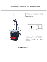
The tyre changer must be transported in its
original packing and stowed in the position
shown on the external packing.
- Packing dimensions:
• width .................................1543 mm
• depth ................................1140 mm
• height ................................ 1900 mm
- Weight of wooden packing:
• ........................................... kg 380
ambient Conditions for maChine transport
and storage
Temperature: -25° ÷ +55°C.
WARNING
Do not stack other goods on top of the packing
to avoid damaging it.

- EnglIsh -
Operator’s manual 45
handling
To move the packing, insert the tines of a fork-lift
truck into the slots on the base of the packing
itself (pallet) (1-g. 1).
Before moving the machine, refer to the HOI-
STING/HANDLING section.
UNPACKING/ASSEMBLY
WARNING
Take utmost care when unpacking, assembling,
hoisting and installing the machine as described
in this heading.
Keep the original packing in good conditions
to be used if the equipment has to be shipped
in the future.
Failure to comply with these instruction may
damage the machine and risk the operator’s
safety.
Remove the upper part of the packing.
The machine is fully assembled, comprising
two main groups, 2- the machine, 3- the ac-
cessories, (g. 1).
Identify the points 4 and 5 at which the machine
is anchored to the pallet and proceed to remove
xing devices. (g. 1)
2
4
1
3
5

46
- EnglIsh -
Operator’s manual
HOISTING/HANDLING
In order to remove the machine from the pallet,
hook it up as shown in g. 2.
This hoisting point must be used whenever you
need to change the installation position of the
machine. Do not attempt to move the machine
until it has been disconnected from the electri-
city and compressed air supply systems.
2
INSTALLATION CLEARANCES
WARNING
The installation site must be chosen in strict
compliance with the relevant regulations
regarding Safety in the workplace.
IMPORTANT: for correct, safe use of the equi-
pment, users must ensure a lighting level of at
least 300 lux in the place of use.
CAUTION
If the machine is installed outdoors, it must
be properly sheltered under a roof.
WARNING
The oor must be able to withstand a load
equal to the sum of the weight of the equip-
ment itself and the maximum payload, bearing
in mind the support surface area and eventual
anchor xtures used.
Install the tyre changer in the chosen work po-
sition, complying with the minimum clearances
shown in g. 3.
The machine must be placed on a horizontal
surface, preferably concrete or tiled oor. Do
not install on unstable or damaged surfaces.
The surface on which the machine rests must
withstand the loads transmitted during ope-
ration. The surface must have a load-carrying
capacity of at least 500 kg/m
2
.
3
900
1200
500
ambient working Conditions
- Relative humidity 30% ÷ 95% without conden-
sation.
- Temperature 0°C ÷ 50°C.
WARNING
Use of the machine in a potentially explosive
atmosphere is not permitted.

- EnglIsh -
Operator’s manual 47
ELECTRICAL AND
PNEUMATIC CONNECTIONS
WARNING
Any connections to the workshop electrical
panel are the customer’s responsibility, and
must be made by staff qualied in accordance
with the relevant legal requirements.
Before connecting the air supply system, make
sure the machine is set up as in g. 4:
Pedal 13 fully up, column forward.
4
13
- The electrical supply must be suitably sized
in relation to:
• the machine input power as specied in the
corresponding machine data plate;
• the distance between the machine and the
power supply hook-up point, so that voltage
drops under full load do not exceed 4% (10%
during start-up) compared with the rated
voltage specied on the data plate.
- User must:
• t a power plug on the power supply lead
in compliance with the relevant safety
standards;
• connect the machine to its own electrical
connection - A g. 5 - and t a differential
safety circuit-breaker with 30 mA residual
current;
A
B
5
• t fuses to protect the power supply line,
rated as indicated on the general wiring
diagram in this manual;
• install an efcient earthing circuit to protect
the workshop electrical system.
- In order to prevent the machine from being
used by unauthorised personnel, it is advisable
to disconnect the power supply plug when the
machine remains idle (switched off) for long
periods.
- If the machine is connected directly to the
power supply by means of the main electrical
board without a separate plug, install a key-
operated switch or a suitable lock-out device
to restrict machine use to authorised personnel
only.
WARNING
A good grounding connection is essential for
correct operation of the machine.

48
- EnglIsh -
Operator’s manual
NEVER connect the earth wire to a gas or
water pipe, telephone line or any other un-
suitable objects.
Check that the pressure and ow-rate provided
by the compressed air system are compatible
with those required for proper operation of the
machine - see “Technical Data” section. For
correct machine operation the compressed air
supply line must provide a pressure range from
no less than 8 bar to no more than 16 bar.
Connect the compressed air system by means
of a supply pipe connected to the intake of
the air treatment unit on the REAR SIDE of the
machine base.
Check that there is air lubrication oil in the
Lubricating unit; rell if there is little or no
oil. Use SAE20 oil.
The customer must provide an air cut-off valve
upstream of the air treatment and regulating
device supplied with the machine.
1
6
WARNING
Connection 1 should be considered as an
emergency valve to disconnect the machine
from the air line (g.6)
SAFETY REGULATIONS
The equipment is intended for professional
use only.
WARNING
Only one operator may work on the equip-
ment at a time.
WARNING
Failure to comply with the instructions and
danger warnings may seriously injure opera-
tors and any other person present near the
machine. Do not operate the machine until
you have read and understood all the danger,
warning and caution notices in this manual.
This machine must be used only by qualied
and authorised personnel. A qualied operator
is construed as a person who has read and
understood the manufacturer’s instructions, is
suitably trained, and is conversant with safety
and adjustment procedures to be adhered to
during operations. Operators must not use the
machine under the inuence of alcohol or drugs
which may affect their capacity.
The operator must, in all cases:
- Be able to read and understand all the infor-
mation in this manual.
- Have a thorough knowledge of the capabilities
of this machine.
- Keep unauthorised persons well clear of the
area of operation.
- Make sure the machine has been installed in
compliance with all relevant regulations and
legislation.
- Make sure that all machine operators are
suitably trained, that they are capable of
using the equipment correctly and that they
are adequately supervised.
- Never leave nuts, bolts, tools or any other
equipment on the tyre changer as they may
become entrapped between moving parts.
- Not touch power lines or the inside of electric
motors or any other electrical equipment be-
fore making sure the power supply has been
disconnected.
- Read this manual carefully and learn how to
use the machine correctly and safely.
- Always keep this user and maintenance manual
in an easily accessible place and consult it
whenever necessary.

- EnglIsh -
Operator’s manual 49
WARNING
Do not remove or deface the Danger, Warning
or Instruction decals. Replace any missing or
illegible decals. If one or more decals have
been detached or damaged, replacements can
be obtained from your nearest dealer.
- When using and servicing the machine, ob-
serve the standardised industrial accident
prevention regulations for high voltages.
- Any unauthorised alterations or changes made
to the machine shall automatically release the
manufacturer from any liability for damage or
accidents attributable to such modications.
Specically, tampering with or removing the
safety devices is a breach of the regulations
for Safety in the workplace.
- User must wear personal protective equipment
such as gloves, safety footwear and goggles.
WARNING
When operating or servicing the equipment,
tie back long hair and do not wear loose-tting
clothes, ties, necklaces, rings or wristwatches
which could become entrapped by moving
parts.
DESCRIPTION
The machine is a universal electro-pneumatic
tyre changer, to be used with integral wheels
with drop centre featuring weights and di-
mensions as described in the technical data
section.
It is designed to work effectively on:
- Conventional wheels;
- Reverse rim wheels or wheels without central
hole - (use optional kit);
- Run-at tyres with reinforced sidewalls*.
* WARNING: There are specically studied
procedures for this type of wheels.
NB: It may be difcult and sometimes impossible
to clamp and/or demount wheels of Vintage
cars (cars out of production for over 30 years),
some types of rally wheels and non-standardised
street wheels.
The machine is solidly constructed. It operates
with the wheel in a horizontal position for
both bead breaking and demounting/mounting
operations.
All machine movements are controlled by the
operator by means of a pedal in a pedal board
and manual controls on the console.
The machine is used to easily break the bead,
demount and mount any type of the above
tyres.
In any stage, the machine operates with a
clamped and perfectly centred horizontal wheel
on the turntable.
Wheel loading and unloading operations are
simplied by an ergonomic wheel lift (optio-
nal kit) which minimises the operator effort
required.
The main advantage of the machine is that it
does not have a bead lifter lever.
Its absolutely innovative operating principle
comprises:
- A wheel positioning system that makes use of
the wheel inner side and the machine axial
mounting turntable as references (an optional
reverse rim kit is supplied for rims with drop
centres on the inner side).
- An efcient manual wheel clamping system,
which makes use of the rim central hole by
means of a handle and cones (an optional
clamping kit is supplied for rims with no
central hole).
- A pneumatic bead breaking unit consisting of
two bead breaker disc holders. Its pneumatic

50
- EnglIsh -
Operator’s manual
vertical movement is independent and acti-
vated from the console; the disc horizontal
positioning is manual, mechanically activated
from the console and it allows the simultaneous
positioning of the bead breaker discs. Bead
breaking is ensured by the disc movement,
with a controlled penetration commanded by
an operator.
- A head, installed on a mobile column with a
rear opening, consists of a xed supporting
nucleus that facilitates tyre mounting and a
pivoted mobile xed nucleus that facilitates
an optimal tyre demounting without using the
bead lifter lever*.
* In a very few cases, an accessory supplied cal-
led manual “help” may be of use in simplifying
demounting where excessive lubricant has been
applied or for tyres coupled to special rims.
- A pedal-controlled pneumatically operated
wheel lift (optional) which loads and unloads
the wheel to and from the working position
The tyre changer has also enabled the achie-
vement of the following objectives:
- Minimised physical effort on the part of the
operator
- No risk of damage to rim and tyre
Each machine carries a plate with its identi-
cation data and some technical data.
As well as the manufacturer’s details, it in-
dicates:
Mod. - Machine model; V - power supply voltage
in Volts; A - Input voltage in Amperes; kW -
Absorbed power in kW; Hz - Frequency in Hz;
Ph - Number of phases; bar - Operating pressure
in bar; Serial No. - Machine serial number; ISO
9001 - Certication of the company's Quality
System; EC - EC marking.
WARNING
It is forbidden to modify or remove the data
in the plate.
TECHNICAL DATA
- Overall dimensions (see g. 7):
• Length ...............................1235 min
– 1784 max
• Width.................................928 min –
2018 max
• Height ........... ..................... 1210 min
– 2224 max
- Wheel dimension range:
• rim diameter ... ............. from 12” to 28”
• maximum tyre diameter .... 1080 mm (42”)
• max tyre width .............................15”
(from wheel supporting base)
- Turntable:
• resting side: ...................... ......anged
• centring: ...................... ......... on cone
• clamping: .............. pneumatic-automatic
• drive system: . 2-speed motor-inverter
unit
• rotation torque: ..................... 1200 Nm
• rotation speed: ...................... 6-15 rpm
- Bead Breaking Unit:
• tool: ........................................ disc
• positioning in relation to rim: ...............
manual with mechanical clamping
• penetration: ............................guided
• maximum bead breaking range ..A = 670 mm
(g.8)
• bead breaker stroke ..............B= 540 mm
(g.8)
• bead breaking cylinder force: .......5500 N
- Wheel lifter: ...................... ON REQUEST
• lifting operation: .................. automatic
manual tilting
• activation: .........................pneumatic
• lifting capacity: ......................... 85 kg

- EnglIsh -
Operator’s manual 51
- Power supply:
• electric, 1Ph ........................230V-0.75
kW 50Hz/60 Hz
• electric, 1Ph (alternate) ..........110V-0.75
kW 50Hz/60 Hz
• pneumatic operating pressure: ...... 10 bar
- Weight: ....................................380 kg
- Weight of electrical/
electronic components: ................11.5 kg
- Noise level:
• A-weighted sound pressure level
(L
pA
) at the working position .... < 70 dB (A)
2224 max
1784 max
2018 max
7
B
A
WHEEL SUPPORT
BEAD BREAKER TRAVEL
MAXIMUM BEAD
BREAKING RANGE
8
The noise levels indicated correspond to emis-
sion levels and do not necessarily represent safe
operating levels. Although there is a relationship
between emission levels and exposure levels,
this cannot be used reliably to establish whether
or not further precautions are necessary. The
factors which determine the level of exposure
to which the operator is subject to include the
duration of the exposure, the characteristics
of the workplace, other sources of noise, etc.
The permitted exposure levels may also vary
according to the country. However, this informa-
tion will enable machine users to make a more
accurate assessment of hazard and risks.

52
- EnglIsh -
Operator’s manual
OPTIONAL ACCESSORIES
SUPPLIED ON REQUEST
For codes not included here, see the “ORI-
GINAL ACCESSORIES” handbook supplied with
the machine.
8-11100127 ............................. Lifter Kit
8-11100128 ..................... Bead presser Kit
8-11100159 .................... Accessory holder
8-11100160 ...................Quick beading Kit:
............................................ T.I. system
RIM CENTRING/CLAMPING
ACCESSORIES -
DESCRIPTION AND USE
For the diagram concerning optimal use of the
centring and clamping accessories depending on
rim type, see the accessories handbook supplied
with the machine.
SPECIFIED CONDITIONS OF USE
The tyre changer is designed exclusively to
mount and demount tyres, using the tools with
which it is equipped, following the instructions
in this manual.
WARNING
Any other operations carried out on the
machine are considered as improper use and
shall be construed as negligence.
These machines are equipped with an ination
system independent from any other function
described above. Take great care when using
it (read the INFLATION chapter).
WARNING
You are strongly advised not to use non-original
equipment or tools.
The operator's position during the different
operating stages is shown in g. 9.
9
A
WARNING
Keep hands well away from machine moving
parts.
WARNING
To stop the machine in an emergency:
- disconnect the power supply plug;
- isolate the compressed air supply network by
disconnecting the (quick-coupling) shut-off
valve (g. 6).

- EnglIsh -
Operator’s manual 53
MAIN OPERATING PARTS
WARNING
Get to know your machine: the best way to
prevent accidents and obtain top performance
is to get to know exactly how it works. Learn
the function and location of all the controls.
Check carefully that each of the controls ope-
rates properly. To avoid any risk of accidents
and injuries, the machine must be installed and
operated correctly and serviced regularly.
The machine main operating parts are shown
in g. 10.
1 Body
2 Centring handle (device for clamping the
wheel to the turntable).
3 Movable head for tyre mounting/de-
mounting.
4 Tilting column.
5 Demounting tool control cylinder.
6a Cylinder for movable head descent.
7 Console.
8 Wheel resting and centring unit.
9 Clamping control handle.
10 Bead breaking unit.
11 Bead breaker disc.
12 Grease tank.
13 Tilting column pedal.
14 Ination pedal.
15 Rotation pedal.
17
Pressure gauge for reading ination pressure.
18 Filter Regulator + Lubricator Unit (regulates
pressure, lters, removes humidity of and
lubricates the compressed air supplied).
19 Data plate.
20 Deation push-button
21 Control valve for upper bead breaking arm
ascent descent.
22 Doyfe inator chuck.
23 Control valve for lower bead breaking arm
ascent descent.
24 Control valve for locking dual-position bead
breaker supports.
25 Control push-button for upper bead breaker
disc penetration.
(the bead breaker disc is activated by pres-
sing this push-button; every time the lever
21 is operated upwards –the bead breaker
disc moves away from the rim-, the bead
breaker disc is deactivated).
26 Control push-button for lower bead breaker
disc penetration.
(the bead breaker disc is activated by pressing
this push-button; every time the lever 23 is
operated downwards –the bead breaker disc
moves away from the rim-, the bead breaker
disc is deactivated).
27 Control push-button for bead breaking unit
unlocking and opening.
28 Head control lever.
29 Wheel lifter pedal (optional).
30 Vertical arm ascent/descent push-button:
A: ascent B: descent C: locked
31 Wheel clamping pedal

54
- EnglIsh -
Operator’s manual
15
1
12
13 29
31
14
2
18
3
8
9
5
28
6
30
7
10
11
7
4
17
27
25
26
23
20
24
22
21
30
C B A
10

- EnglIsh -
Operator’s manual 55
key to danger/warning deCals
Risk of crushing.
Never place any part of the body, particularly
your hands, between the bead breaker disc or
the demounting/mounting tools and the wheel.
Never place your hand between the turntable
and the wheel.
Risk of crushing.
Never place any part of the body between the
wheel lifter and any other component with
which it comes into contact.
NEVER stand behind the machine.
Only one operator may operate and use the
machine.
NEVER stand or walk close to the machine when
it is in operation. The tool-holder arm and the
bead breaking unit have a lateral opening.
NEVER stand behind the ma-
chine.
Risk of crushing.
Never place any part of the body, particularly
your hands, between the demounting/mounting
tool and the wheel.
Preliminary checks
Check that there is a pressure of at least 8 bar
on the pressure gauge of the Filter Regulator
+ Lubricator unit.
Check that the machine has been adequately
connected to the power mains.
deCiding from whiCh side of the wheel
the tyre must be demounted
See g. 11.
Find the position of the drop centre A on the
wheel rim. Find the largest width B and the
smallest width C.
The tyre must be demounted or mounted with
the wheel positioned on the turntable with the
side with the smallest width C facing upward.
11
C
A
B
A
A
B
A
B
C
C

56
- EnglIsh -
Operator’s manual
11
C
A
B
D
speCial instruCtions
Some types of wheels on the market require
special procedures and precautions which differ
from the standard procedure.
This applies in particular to the following types
of wheels:
Alloy rim wheels: some wheels have alloy rims
where the drop centre A is very small or non-
existent - g. 11-B. These rims are not approved
by the DOT (Department of Transportation)
standards - these initials certify that tyres
comply with the safety standards adopted by
the United States and Canada (these wheels
cannot be sold in these markets).
DANGER
Take utmost caution when mounting the tyre.
The rim and/or the tyre may be damaged ac-
cidentally, with the risk of the tyre exploding
during the ination stage.
European style high-performance wheels
(asymmetric curvature) - g. 11-C: some Eu-
ropean wheels have rims with very pronounced
curvature C, except in the area of the valve hole
A where the curvature is less pronounced B. On
these wheels the bead must rst be broken in
correspondence with the valve hole, on both
the top and bottom sides of the wheel.
Wheels with low pressure indicator system -
g. 11-D: see the chapter on “Procedures for
wheels tted with valve or strap-on sensors”
NB:
When working on "weak" rims (i.e. a central
hole with thin, projecting edges - see next
gure), or rims with gaps, we recommend
using the universal turntable for blind rims
accessory.
11a

- EnglIsh -
Operator’s manual 57
PRACTICAL HINTS, ADVICE
AND USEFUL INFORMATION
WARNING
To read before using the machine.
The following information is highly signicant
as it facilitates the operator’s job and/or helps
clarify any doubts that might arise.
praCtiCal hints
• Upon demounting, over-lubrication and/or
an unusually shaped rim edge may cause the
tyre to slip on the rim, making demounting
difcult. First, try using the bead breaker disc
in an upward direction to raise the tyre. Other-
wise, to speed up the procedure simply place
the manual Help accessory between the tyre
and the edge of the rim. This will help lifting
the bead quickly off the rim so that it can be
demounted (g. 12).
12
• Upon demounting, if the tool cannot comple-
tely overturn the tyre bead to allow demounting
to start, the tyre bead may still be, or just have
been, inserted at 180° to the demounting zone.
In this case, it is essential to restore the ideal
condition, with the tyre bead inside the well of
the rim. This operation can be assisted with any
tool you wish (clamp supplied with the machine,
pliers, bead presser or lever) (g.12A).
12a
• Upon demounting, if the tool cannot keep
the tyre bead engaged to allow demounting
to start, the tyre bead may still be inserted
on the underside. Try using the bead breaker
disc in an upward direction both to break the
tyre bead again and to help maintain a grip on
it (g. 12B).
12b

58
- EnglIsh -
Operator’s manual
adviCe
To prevent any rim damage, the plastic insert
under the head (g. 13) must be replaced every
2 months or sooner, if excessively worn. A spare
insert is supplied with the machine.
13
information
Any noise heard when the tool head engages with
the tyre is normal. The noise is caused by the
mechanical return of the tool and not because
the tool has hit the rim. Even if the tool does
touch the rim as the tyre is engaged, this will
not damage the rim in any way. The pressure
applied is very low. If you wish to prevent this
noise, simply press the bead breaker disc harder
against the bead when picking it up.
WARNING
Bead breaking is well known to be a dangerous
operation. It must be carried out in accordance
with the instructions below.
Wheel for cars, off-road and light commercial
vehicles.
GUIDE TO THE
CORRECT USE OF THE
MACHINE
WARNING
Read the “PRACTICAL HINTS, ADVICE AND USEFUL
INFORMATION” section above with great care.
TYRE DEMOUNTING
WARNING
BEFORE STARTING THE DEMOUNTING OPERA-
TION, MAKE SURE THE MACHINE IS SET WITH
THE COLUMN TILTED FROM THE REAR AND
THE DUAL-POSITION BEAD BREAKER SUPPORT
IS NOT LOCKED.
1 • Wheel loading (g. 14-14a)
- Place the wheel on the lifter OPTIONAL AC-
CESSORY SUPPLIED ON REQUEST
- Lift the wheel operating on pedal 29 OPTIONAL
ACCESSORY SUPPLIED ON REQUEST
14

- EnglIsh -
Operator’s manual 59
- Manually lay the wheel onto the turntable
(8) and lower the lifter by operating on pedal
29.
- When positioning the wheel on the turntable,
also take care to centre the movable centring
pin, placed radially on the turntable, in one
of the xing bolt holes.
29
31
14a
14a
2 • Clamping the wheel to the turntable
(g. 15)
- Choose the correct cone for the hole of the
rim.
- Press the clamping pedal 31.
- Put the clamping device in the drop centre of
the wheel (Fig 15).
- Make sure the cone and the rim are perfectly
centred.
- Release the pedal 31.
15
3 • Tyre deation (g. 16)
- Operate the valve and fully deate the
tyre.
16
4 • Bead breaker positioning (g. 17-17a)
- Move the bead breaking unit from the its rest
to its operating position
- Move the disc towards the rim:
- the horizontal movement is achieved by
hand, rotating the console
- the vertical movement is achieved by
operating control 21

60
- EnglIsh -
Operator’s manual
- Once the desired distance is reached (a gap of
2-3 mm should be left between the edge of the
rim and the bead breaker disc), operate the
(control 24) to inhibit any further horizontal
movement.
NB: SIMULTANEOUS CLAMPING BY BOTH ARMS
IS ACHIEVED THROUGH THIS CONTROL. THE-
REFORE, THE LOWER ARM IS READY FOR BEAD
BREAKING, AND THIS POSITION WILL BE STORED
IN THE MACHINE MEMORY UNTIL CONTROL 24
IS UNLOCKED.
17
17a
2-3mm
/