Westinghouse FG7T(C,L) - VS Installation guide

Category
Cookers
Type
Installation guide
LP & HIGH ALTITUDE LP GAS CONVERSION KIT FOR INSTALLATIONS IN THE UNITED STATES
For *G7 / *GC2 & GUH* / GDD* Series Furnaces & Appliances Using Honeywell Gas Valves
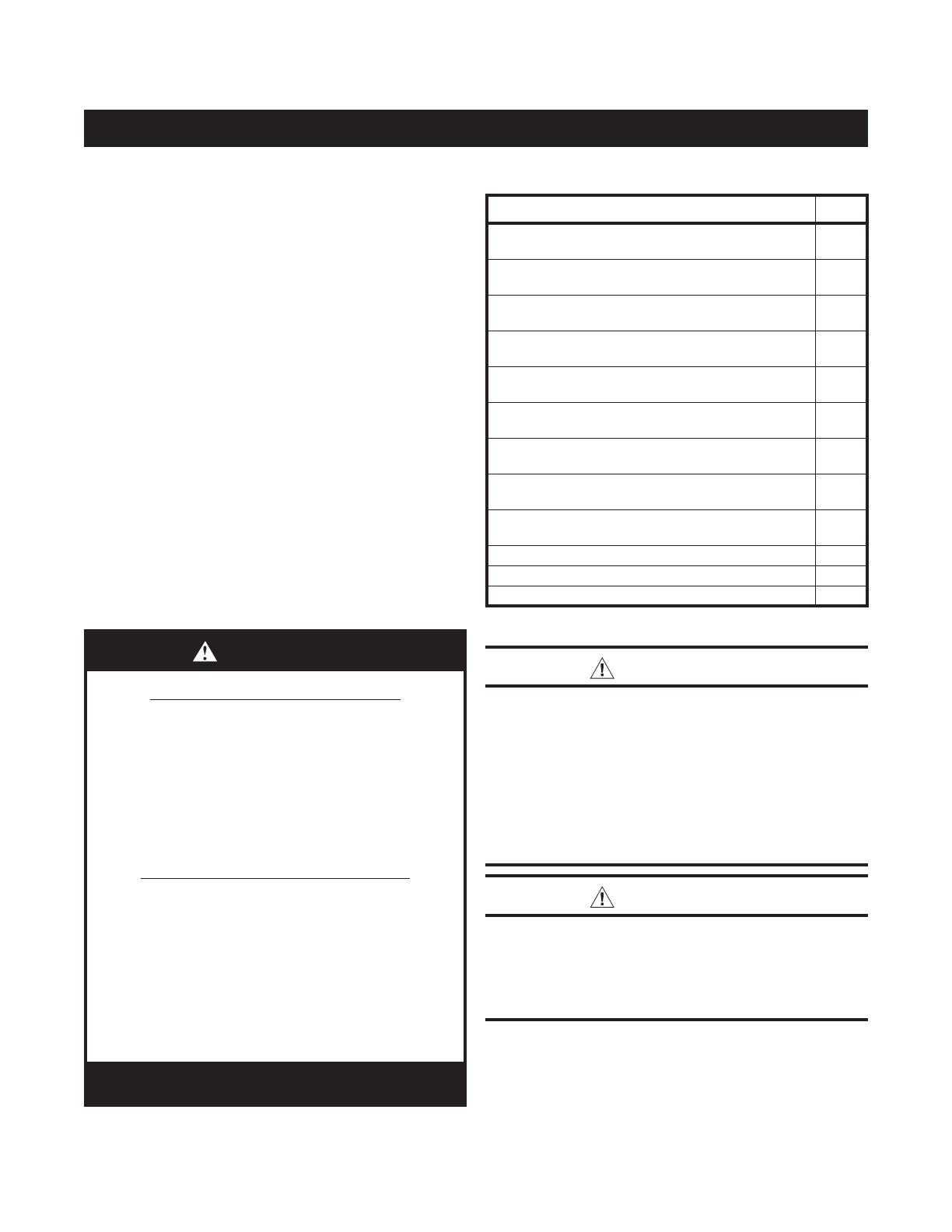
Table 1. LP Gas Conversion Kit
DESCRIPTION QTY
Honeywell Conversion Kit 396221
(to convert VR8205S2890 or VR8215S1289)
1
Honeywell Conversion Kit 396021
(to convert VR8205Q2381)
1
Honeywell Conversion Kit 50033841
(to convert VR9205Q1127)
1
#55 Drill Size Burner Orifice Kit
(contains (7) 661055)
1
#56 Drill Size Burner Orifice Kit
(contains (7) 661056)
1
#57 Drill Size Burner Orifice Kit
(contains (7) 661057)
1
#59 Drill Size Burner Orifice Kit
(contains (3) 661059)
1
#60 Drill Size Burner Orifice Kit
(contains (3) 661060)
1
#61 Drill Size Burner Orifice Kit
(contains (3) 661061)
1
Conversion Warning Label 1
Conversion Information Label 1
Installation Instructions 1
BEFORE THE CONVERSION
IMPORTANT: Please read all instructions before
converting the furnace. Pay attention to all safety warnings
and any other special notes highlighted in the manual. Safety
markings are used frequently throughout this manual to
designate a degree or level of seriousness and should not
be ignored. WARNING indicates a potentially hazardous
situation that if not avoided, could result in personal injury
or death.
This conversion kit is only to be used to convert natural
gas furnaces to LP/Propane gas in the United States. For
installations in Canada, the Canadian conversion kit must
be used.
Table 1 is a detailed listing of the components in the LP gas
conversion kit. Please check the contents of the conversion
kit with that of the parts listing, and familiarize yourself with
each component.
Use caution when servicing or removing components from
the appliance. Personal injury can occur from sharp metal
edges present in all sheet metal constructed equipment.
IMPORTANT: When converting a low NOx furnace from
natural gas to LP/Propane gas, it is necessary to remove
the NOx Baffles from the furnace.
WARNING:
All gas piping must conform with local building
codes, or in the absence of local codes, with the
most recent edition of the National Fuel Gas Code
ANSI Z223.1. DO NOT attempt to modify, or tap
into existing gas lines yourself. Fire or explosion
may result causing property damage, personal
injury or loss of life. Failure to follow the safety
warnings exactly could result in serious injury,
death or property damage.
WARNING:
All electrical wiring must comply with the latest
edition of the National Electrical Code ANSI/
NFPA 70. Failure to follow these instructions
could result in possible damage to equipment,
serious personal injury, or death.
WARNING
FIRE OR EXPLOSION HAZARD
Failure to follow safety warnings exactly could
result in serious injury or property damage.
Installation and service must be performed
by a qualified installer, service agency or the
gas supplier.
Do not store or use gasoline or other
flammable vapors and liquids in the vicinity
of this or any other appliance.
WHAT TO DO IF YOU SMELL GAS
Do not try to light any appliance.
Do not touch any electrical switch; do not
use any phone in your building.
Leave the building immediately.
Immediately call your gas supplier from a
neighbors phone. Follow the gas suppliers
instructions.
If you cannot reach your gas supplier, call
the fire department.
DO NOT DESTROY. PLEASE READ CAREFULLY &
KEEP IN A SAFE PLACE FOR FUTURE REFERENCE.
INSTALLATION INSTRUCTIONS
2
CONVERTING TO LP/PROPANE GAS AT
ALTITUDES BETWEEN ZERO & 10,000 FT.
Converting single stage valves to LP/Propane requires the
replacement of the burner orifices and/or the spring found
under the cap screw in the pressure regulator. Converting
2 - stage valves to LP/Propane requires the replacement of
the burner orifices and/or the stem/spring assembly in the
pressure regulator.
Table 2 (page 3), provides the manifold pressure for altitudes
above 2,000 feet.
WARNING:
Shut off the gas supply at the manual gas shutoff
valve, before disconnecting the electrical power.
A fire or explosion may result causing property
damage, personal injury or loss of life. Failure to
follow the safety warnings exactly could result in
serious injury, death or property damage.
WARNING:
To avoid electric shock, personal injury, or death,
turn off the electric power at the disconnect or the
main service panel before making any electrical
connections.
WARNING:
The reduction of input rating necessary for high
altitude installation may only be accomplished
with factory supplied orifices. Do not attempt to
drill out orifices in the field. Improperly drilled
orifices may cause fire, explosion, carbon
monoxide poisoning, personal injury or death.
Before You Convert the Gas Valve
1. Turn the thermostat OFF or to its lowest temperature
setting.
2. Verify the gas supply is shut OFF.
3. Verify the electrical power to the appliance is turned OFF.
Removing The Burner Orifices
1. Set the thermostat to the OFF position, or its lowest
temperature setting.
2. Shut OFF the gas supply at the manual shutoff valve
located outside of the appliance.
3. Turn off all electrical power to the appliance.
4. Remove the door from the burner compartment.
5. Move the gas valve ON/OFF switch to the OFF position
as shown in Figure 1. For VR8205Q2381 gas valves, turn
the knob to the OFF position.
6. Remove the wires from the terminals of the gas valve.
7. Remove the supply gas piping from the gas valve inlet.
8. Carefully remove four screws securing the gas manifold
assembly to the burner assembly.
9. Set the screws aside and remove the gas manifold assembly
from the appliance.
10. Carefully remove the burner orifices from the gas manifold
assembly.
11. Read the rating plate affixed to the appliance to determine
its rated input (Btu/hr) and the size of the factory installed
orifices.
IMPORTANT NOTE:
Before installing an orifice, check the side or face of
the orifice for the drill number to ensure that it is the
appropriate size.
12. Install the appropriate LP/Propane gas burner orifices
into the gas manifold assembly.
NOTE: To prevent cross threading, hand tighten the orifices
into the gas manifold assembly until snug, then tighten
with a wrench.
WARNING:
Do not use Teflon tape or pipe joint compound
on the orifice threads. The hole in the orifice
may become blocked and cause fire, explosion,
property damage, carbon monoxide poisoning,
personal injury, or death.
13. Reinstall the gas manifold assembly to the burner
assembly with the 4 screws, that were removed earlier.
NOTE: It is important that the center of the orifices are
aligned with the center of the burners.
14. Reconnect the gas piping to the gas valve inlet.
15. Reconnect the wires to the gas valve terminals.
3
FURNACE
MODELS
INPUT
ALTITUDE ABOVE SEA LEVEL
0 TO
1,999 FT
2,000 TO
2,999 FT
3,000 TO
4,999 FT
5,000 TO
5,999 FT
6,000 TO
7,999 FT
8,000 TO
10,000 FT
ORIFICE
SIZE
MANIFOLD
PRESSURE
ORIFICE
SIZE
MANIFOLD
PRESSURE
ORIFICE
SIZE
MANIFOLD
PRESSURE
ORIFICE
SIZE
MANIFOLD
PRESSURE
ORIFICE
SIZE
MANIFOLD
PRESSURE
ORIFICE
SIZE
MANIFOLD
PRESSURE
*G7SA / *GC2SA
*G7SK / *GC2SK
GUH80A* / GDD80A*
45,000 57 10.0 57 9.0 57 8.5 59 10.0 59 9.0 59 8.5
54,000 56 10.0 56 9.0 56 8.5 57 10.0 57 9.0 57 8.5
72,000 56 10.0 56 9.0 56 8.5 57 10.0 57 9.0 57 8.5
90,000 56 10.0 56 9.0 56 8.5 57 10.0 57 9.0 57 8.5
108,000 56 10.0 56 9.0 56 8.5 57 10.0 57 9.0 57 8.5
126,000 56 10.0 56 9.0 56 8.5 57 10.0 57 9.0 57 8.5
*G7SC / *GC2SC
*G7SL / *GC2SL
*G7SD / *GC2SD
*G7SM / *GC2SM
GUH92A* GDD92A*
GUH95A / GDD95A*
38,000 (SC) 56 10.0 56 9.0 56 8.5 57 10.0 57 9.0 57 8.5
38,000 (SD) 60 10.0 60 9.0 60 8.5 61 8.5 61 8.0 61 7.5
54,000 56 10.0 56 9.0 56 8.5 57 10.0 57 9.0 57 8.5
72,000 56 10.0 56 9.0 56 8.5 57 10.0 57 9.0 57 8.5
90,000 56 10.0 56 9.0 56 8.5 57 10.0 57 9.0 57 8.5
108,000 56 10.0 56 9.0 56 8.5 57 10.0 57 9.0 57 8.5
118,000 55 10.0 55 9.0 55 8.5 56 10.0 56 9.0 56 8.5
120,000 55 10.0 55 9.0 55 8.5 56 10.0 56 9.0 56 8.5
*G7TA / *GC2TA
*G7TK / *GC2TK
60,000 55 10.0 55 9.0 55 8.5 56 10.0 56 9.0 56 8.5
80,000 55 10.0 55 9.0 55 8.5 56 10.0 56 9.0 56 8.5
100,000 55 10.0 55 9.0 55 8.5 56 10.0 56 9.0 56 8.5
120,000 55 10.0 55 9.0 55 8.5 56 10.0 56 9.0 56 8.5
140,000 55 10.0 55 9.0 55 8.5 56 10.0 56 9.0 56 8.5
Low Fire 4.2 4.2 4.2 4.2 4.2 4.2
*G7TC / *GC2TC
*G7TL / *GC2TL
GUH95T*
60,000 55 10.0 55 9.0 55 8.5 56 10.0 56 9.0 56 8.5
80,000 55 10.0 55 9.0 55 8.5 56 10.0 56 9.0 56 8.5
100,000 55 10.0 55 9.0 55 8.5 56 10.0 56 9.0 56 8.5
120,000 55 10.0 55 9.0 55 8.5 56 10.0 56 9.0 56 8.5
Low Fire 4.2 4.2 4.2 4.2 4.2 4.2
*G7TE / *GC2TE
*G7TN / *GC2TN
GUV96T*
60,000 55 10.0 55 9.0 55 8.5 56 10.0 56 9.0 56 8.5
80,000 55 10.0 55 9.0
55 8.5 56 10.0 56 9.0 56 8.5
100,000 55 10.0 55 9.0 55 8.5 56 10.0 56 9.0 56 8.5
115,000 55 10.0 55 9.0 55 8.5 56 10.0 56 9.0 56 8.5
Low Fire 4.2 4.2 4.2 4.2 4.2 4.2
Table 2. Liquid Propane Conversion Chart
Figure 1. Burner & Manifold Assembly
Terminals
Orifices
ON/OFF
Switch
Gas Valve
Gas Valve
Inlet
Manifold
Assembly
Screws (x4)
Burner
Assembly
Burners
4
Figure 4. Spring / Stem Assembly Removal
Screws (x2)
Regulator Co
ver
Assembly
Spring / Stem
Assembly
2 Adjustment Screws
(beneath cap)
Single Stage Honeywell Valves
Models: VR8205S2890 or VR8215S1289
IMPORTANT NOTE:
When converting to LP/Propane gas from natural gas,
the black spring in the gas valve must be replaced by
the red spring in the kit.
1. Remove the cap screw from the gas valve as shown in
Figure 2.
Figure 3. Pressure Regulator Spring &
Adjustment Screw Removal
Spring
Adjusting Screw
(VR8205S2890 shown)
Figure 2. Cap Screw Removal
Cap screw
(VR8205S2890 sho
wn)
2. Remove and discard the plastic pressure regulator
adjustment screw from the gas valve. See Figure 3.
3. Remove the black colored spring from the gas valve.
4. Install the red spring from the conversion kit.
5. Install the new adjusting screw from the kit.
6. Check and adjust the regulator setting. See Gas Pressure
Adjustment Section (page 5).
7. Reinstall the cap screw.
8. Affix the label from the conversion kit to the gas valve.
2 - Stage Honeywell Valves
Model VR8205Q2381
IMPORTANT NOTE:
When converting to LP/Propane gas from natural gas,
the white stem/spring assembly in the gas valve must be
replaced by the black stem/spring assembly in the kit.
1. Remove two screws securing the pressure regulator cover
assembly to the gas valve. Do not discard the screws. See
Figure 4.
2. Remove the pressure regulator cover assembly from the
gas valve.
3. Remove and discard the existing spring / stem assembly
from the gas valve.
4. Install the replacement spring / stem assembly from the
conversion kit.
5. Reinstall the pressure regulator cover assembly onto the
gas valve.
6. Install the two screws (from step 1)and tighten.
7. Affix the label from the conversion kit to the gas valve
5
GAS PRESSURE ADJUSTMENT
Measuring the Supply Gas Pressure
1. Turn OFF the gas supply at the manual valve located on
the outside of the unit.
2. Using a 3/16” Allen wrench, remove the plug from the inlet
pressure tap (INLET side of gas valve). See Figure 6.
3. Install an 1/8” NPT pipe thread fitting, that is compatible
with a Manometer or similar pressure gauge.
4. Connect the Manometer or pressure gauge to the Inlet
Pressure Tap.
5. Turn ON the main gas supply at the manual valve.
6. Check and adjust the incoming gas line pressure to 11.0-
14.0 inches Water Column for LP/Propane gas.
7. Turn OFF the gas supply at the manual valve.
8. Disconnect the Manometer or pressure gauge.
9. Remove the NPT fitting and reinstall the INLET pressure
tap plug. Hand tighten the plug first to prevent cross-
threading. Tighten with 3/16 Allen wrench.
Lighting & Adjustment of the Appliance
WARNING:
FIRE OR EXPLOSION HAZARD
Failure to follow safety warnings exactly could
result in serious injury or property damage.
Never test for gas leaks with an open flame. Use
a commercially available soap solution made
specifically for the detection of leaks to check
all connections. A fire or explosion may result
causing property damage, personal injury or
loss of life.
1. Turn ON the manual gas valve, located on the outside of
the unit to the ON position.
2. Check all gas connections for leaks with a soap and water
solution. If the solution bubbles there is a gas leak which
must be corrected.
3. Turn on the electrical power to the appliance.
4. Place the gas valve ON/OFF switch/knob to the ON position.
See Figure 6.
5. Set the thermostat above room temperature to begin the
heating cycle of the furnace.
6. Check that the furnace ignites and operates properly. Refer
to the installation instructions provided with the unit for the
normal operating sequence.
7. After ignition, visually inspect the burner assembly to
ensure that the flame is drawn directly into the center of
the heat exchanger tube. In a properly adjusted burner
assembly, the flame color should be blue with some light
yellow streaks near the outer portions of the flame.
NOTE: The ignitor may not ignite the gas until all air is bled
from the gas line. If the ignition control locks out, turn the
thermostat to its lowest setting and wait one minute then
turn the thermostat above room temperature and the ignitor
will try again to ignite the main burners. This process may
have to be repeated several times before the burners will
ignite. After the burners are lit, check all gas connections
for leaks again with the soap and water solution.
Figure 5. Pressure Regulator Spring &
Adjustment Screw Removal
High Fire
Cap Screw
High Fire
Adjustment Scr
ew
Low Fire
Cap Screw
Low Fire
Adjustment Scr
ew
Spring
Spring
Model VR9205Q1127
IMPORTANT NOTES:
When converting to LP/Propane gas from natural
gas, the springs from gas valve must be replaced
by the larger springs from the kit. The LP/Propane
springs for both HIGH & LOW fire are the same size,
shape and color.
Use only a Torx-25 or 3/16” flathead screwdriver
when removing adjustment screws or during
pressure adjustment.
1. Remove the HIGH fire cap screw. See Figure 5.
2. Remove and discard the HIGH fire adjustment screw from
the gas valve.
3. Remove the spring from the gas valve and discard.
4. Install a larger spring from the conversion kit.
5. Install a new adjusting screw from the kit.
6. Repeat steps 1 - 5 for replacement of the LOW fire spring
and adjustment screw.
7. Check and adjust the regulator setting. See Gas Pressure
Adjustment Section.
8. Reinstall the cap screws on the HIGH and LOW regulators.
Plastic replacement cap screws are provided in the
conversion kit.
9. Affix the label from the conversion kit to the gas valve.
6
Removing the Manometer/Pressure Gauge
After the manifold pressure is properly adjusted, the
Manometer or pressure gauge must be removed from the
gas valve.
1. Turn the thermostat to its lowest setting.
2. Turn OFF the main gas supply to the unit at the manual
shut-off valve, which is located outside of the unit.
3. Turn OFF all of the electrical power supplies to the unit.
4. Remove the pressure gauge adapter from the gas valve
and replace it with the 1/8” NPT manifold pressure plug
that had been removed earlier. NOTE: Make sure the plug
is tight and not cross-threaded.
5. Turn ON the electrical power to the unit.
6. Turn ON the main gas supply to the unit at the manual
shut-off valve.
COMPLETING THE CONVERSION
WARNING:
Do not alter or remove the original rating plate
from the furnace.
1. Attach the following labels:
The conversion warning label (P/N 703935) should be
affixed to the outside of the unit door.
The conversion information label (P/N 703942) should be
affixed near the rating plate on the inside of the control
area.
The gas valve conversion label should be affixed on the
gas valve.
NOTE: Each label should be prominently visible after
installation.
2. Reinstall the appliance door.
3. Run the appliance through 3 complete cycles to assure
proper operation.
Measuring the Manifold Pressure
The manifold pressure must be measured by installing a
pressure gauge (Manometer, Magnehelic Meter, etc.) to the
outlet end of the gas valve as follows:
1. Turn off all electrical power to the appliance.
2. Shut OFF the gas supply at the manual shutoff valve
located outside of the appliance.
3. Using a 3/16” Allen wrench, remove the manifold pressure
tap plug located on the outlet side of the gas valve. See
Figure 6 (page 5).
4. Install an 1/8” NPT pipe thread fitting, that is compatible
with a Manometer or similar pressure gauge.
5. Connect the Manometer or pressure gauge to the manifold
pressure tap.
6. Set the room thermostat above room temperature to start
the furnace.
7. Allow the furnace to operate for 3 minutes and then check
the manifold pressure. Compare the measured value
with the value shown in Table 2 (page 3). If the manifold
pressure is not set to the appropriate pressure, then it
must be adjusted.
Adjusting the Manifold Pressure
NOTE: Adjustments must be made to both LOW & HIGH
fire settings when converting two-stage gas valves. High fire
must be adjusted first and then low fire. The Low fire will be
afffected if not adjusted in this order. Refer to Table 2 for
manifold pressures.
1. Single stage gas valve: Remove the cap screw from the
top of the gas valve regulator. See Figure 2 (page 4) for
VR8205S2890 or VR8215S1289 models.
2-stage gas valve: For VR8205Q2381 models, remove
the plastic cap covering the adjustment screws (Figure
4 page 4). For VR9205Q1127 models, remove the cap
screw (Figure 5, page 5).
2. Using a screwdriver or Allen wrench (where appropriate),
slowly turn the adjustment screw till the appropriate manifold
pressure listed in Table 2 is achieved. See Figure 2 for
VR8205S2890 or VR8215S1289 models. See Figure 4
for VR8205Q2381 models or Figure 5 for VR9205Q1127
models.
NOTE: Turning the screw clockwise increases the
pressure, turning the screw counter-clockwise decreases
the pressure. To prevent the screw from backing all the
way out from the valve, turn the screw slowly.
3. Replace and tighten the cap screw or the plastic cap over
the adjustment screw.
IN
ON
OFF
Inlet
Pressure
Ta p
Inlet
Pressure
Ta p
Inlet
Pressure
Ta p
SINGLE STAGE VA LVES
Manifold
pressure
Ta p
Manifold
pressure
Ta p
Manifold
pressure
Ta p
Manifold
pressure
Ta p
2-STAGE VA LVES
Model VR8215S1289
Inlet
Pressure
Ta p
Model VR8205S2890
Model VR8205Q2381
Model VR9205Q1127
ON/OFF
Switch
ON/OFF
Switch
ON/OFF
Knob
ON/OFF
Switch
Figure 6. Inlet & Manifold Pressure Tap Locations
7
The installer performing this work assumes all responsibility for this conversion. These instructions are primarily intended to assist qualified
individuals experienced in the proper installation of these components. Some local codes require licensed installation/service personnel for this
type of equipment. Safety should always be the deciding factor when installing this product and using common sense plays an important role as
well. Improper installation of the components or failure to follow safety warnings could result in serious injury, death, or property damage. After
completing the installation, return these instructions to the Homeowner’s Package for owner-user’s future reference.
Specifications & illustrations subject to change without notice or incurring obligations (09/17).
O’Fallon, MO, © Nortek Global HVAC LLC 2017. All Rights Reserved.
709369B
(Replaces 709369A)
  • Page 1 1
  • Page 2 2
  • Page 3 3
  • Page 4 4
  • Page 5 5
  • Page 6 6
  • Page 7 7
  • Page 8 8

Westinghouse FG7T(C,L) - VS Installation guide

Category
Cookers
Type
Installation guide

Ask a question and I''ll find the answer in the document

Finding information in a document is now easier with AI