Juniper EX4500 Quick start guide
- Category
- Network switches
- Type
- Quick start guide
This manual is also suitable for

EX4500 Switch Quick Start
See the complete EX Series documentation at http://www.juniper.net/techpubs/ .
To install and configure a Juniper Networks EX4500 Ethernet Switch, you need:
z Two mounting brackets and 20 mounting screws (provided)
z For AC systems–an AC power supply (provided), a power cord with a plug appropriate
for your geographical location (provided), and a power cord retainer (provided)
z For DC systems–a DC power supply (provided), DC power source cables (not
provided) with the cable lugs (Molex 190410014 or equivalent
—not provided)
attached
z Ethernet cable with an RJ-45 connector attached (provided)
z Management host, such as a PC, with an Ethernet port (not provided)
z Screws to secure the chassis to the rack or cabinet (not provided)
z Phillips (+) screwdriver, number 2 (not provided)
Part 1: Install a Power Supply in the Switch (If It Is Not Installed)
1. Ensure that you have the correct power supply. The color of the power supply's
ejector lever must match that of the intake or exhaust labels visible through the fan
tray vents.
CAUTION: Operating the switch with an incorrect power supply might cause the
chassis to overheat.
2. Taking care not to touch power supply pins, leads, or solder connections remove the
power supply from the bag.
3. Using both hands, place the power supply in the power supply slot on the rear panel
of the switch and slide it in until it is fully seated.
Part 2: Mount the Switch
These instructions describe mounting the switch on a two-post 19-in. rack. See the EX
Series documentation at http://www.juniper.net/techpubs/ for information about using a
four-post rack.
1. Place the rack in its permanent location, allowing adequate clearance for airflow and
maintenance, and secure it to the building structure.
NOTE: If you are mounting multiple units on the rack, mount the heaviest unit at the
bottom and mount the others from bottom to top in order of decreasing weight.
2. Align the mounting brackets along the front or rear of the side panels of the chassis
depending on whether you are front-mounting or rear-mounting the switch.
3. Attach the mounting brackets to the chassis by using the mounting screws.
NOTE: The switch weighs 37 lb (17 kg). Installing the switch requires one person to lift it
and a second person to secure it to the rack.
4. Have one person lift the switch and position it in the rack, aligning the mounting
bracket holes with the threaded holes in the rack rail. Align the bottom hole in each
mounting bracket with a hole in each rack rail, making sure the chassis is level.
5. Have the second person secure the switch to the rack by using the appropriate
screws. Tighten the screws.
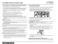
Part 3: Connect Power to the Switch
To connect AC power to the switch:
1. Squeeze the two sides of the power cord retainer clip and insert the L-shaped ends of
the wire clip into the holes in the bracket on each side of the AC appliance inlet.
2. Insert the coupler end of the power cord into the AC appliance inlet.
3. Push the retainer clip toward the cord until the cord slides into the slot in the
adjustment nut. Turn the nut until it is tight against the base of the coupler and the
slot in the nut is turned 90° from the top of the switch.
4. If the AC power source outlet has a power switch, set it to the OFF (0) position.
5. Insert the power cord plug into the power source outlet.
6. If the AC power source outlet has a power switch, set it to the ON (|) position.
7. Repeat these steps for each AC power supply.
To connect DC power to the switch:
WARNING: Ensure that the input circuit breaker is open so that the cable leads will
not become active while you are connecting DC power.
1. Remove the plastic cover from the DC power input terminal block by sliding it off
either to the left or right.
2. Remove the locking screws from each DC power input terminal, using the
screwdriver.
3. Install the negative (-) power cable with lug attached on the -48V DC power input
terminal, securing it with the locking screw. Tighten the locking screw.
4. Install the positive (+) power cable with lug attached on the RTN DC power input
terminal, securing it with the locking screw. Tighten the locking screw.
5. Slide the plastic cover over the input terminal block.
6. Close the input circuit breaker. Verify that the LED on the power supply is lit green
and on steadily.
7. Repeat these steps for each DC power supply.
Part 4: Perform Initial Configuration on a Standalone Switch
NOTE: Before you begin the configuration, enable a DHCP client on the management
PC you will connect to the switch so that the PC can obtain an IP address dynamically.
G
4IGHTEN
ADJUSTMENT
NUT
2ETAINER
CLIP
!DJUSTMENT
NUT
G

Juniper Networks, Junos, Steel-Belted Radius, NetScreen, and ScreenOS are registered trademarks of Juniper Networks, Inc. in the United States and other countries. The Juniper Networks Logo, the Junos logo, and JunosE are
trademarks of Juniper Networks, Inc. All other trademarks, service marks, registered trademarks, or registered service marks are the property of their respective owners. Juniper Networks assumes no responsibility for any inaccuracies
in this document. Juniper Networks reserves the right to change, modify, transfer, or otherwise revise this publication without notice. Products made or sold by Juniper Networks or components thereof might be covered by one or more
of the following patents that are owned by or licensed to Juniper Networks: U.S. Patent Nos. 5,473,599, 5,905,725, 5,909,440, 6,192,051, 6,333,650, 6,359,479, 6,406,312, 6,429,706, 6,459,579, 6,493,347, 6,538,518, 6,538,899,
6,552,918, 6,567,902, 6,578,186, and 6,590,785. Copyright © 2010 Juniper Networks, Inc. All rights reserved. Part Number: 530-038230, Revision 01, 30 December 2010.
NOTE: You must complete the initial configuration using EZSetup within 10 minutes. The
LCD panel displays a count-down timer when the switch is in initial setup mode. The
switch exits EZSetup after 10 minutes and reverts to the factory default configuration,
and the PC loses connectivity to the switch.
1. Transition the switch into initial setup mode using the Menu and Enter buttons to the
right of the LCD panel on the front panel of the switch:
− Press Menu until you see MAINTENANCE MENU. Then press Enter.
− Press Menu until you see EZSetup. Then press Enter.
If EZSetup does not appear as an option in the menu, select Factory Default to
return the switch to the factory default configuration. EZSetup is displayed in the
menu only when the switch is set to the factory default configuration.
− Press Enter to confirm setup and continue with EZSetup.
2. Connect the Ethernet cable from the Ethernet port on the PC to the MGMT port (me0)
on the front panel of the switch.
The me0 interface (the port labeled MGMT) is configured as the DHCP server with
the default IP address, 192.168.1.1. The switch can assign an IP address to the
management PC in the range 192.168.1.2 through 192.168.1.253.
3. From the PC, open a Web browser, type http://192.168.1.1 in the address field, and
press the Enter key.
4. On the J-Web Login page, enter root as the username, leave the password field
blank, and click Login.
5. On the Introduction page, click Next.
6. On the Basic Settings page, enter the hostname, enter and reenter a password,
specify the time zone, and synchronize the switch date and time settings with the
management PC or set them manually and click Next.
7. On the Management Options page, select Out-of-band Management—Configure
management port to configure the management interface and click Next.
8. Specify the IP address and default gateway for the management interface and click
Next.
9. On the Manage Access page, you may select options to enable Telnet, SSH, and
SNMP services.
10. Click Next. The Summary page displays the settings you have selected.
11. Click Finish. The configuration is committed as the active switch configuration.
NOTE: After the configuration is committed, if connectivity between the PC and the
switch is lost, release and renew the IP address by executing the appropriate commands
on the PC or by removing and reinserting the Ethernet cable.
12.In the command line interface (CLI), enter the request chassis pic-mode
intraconnect operational mode command to set the PIC mode to intraconnect.You
can continue configuring the switch with the CLI or the J-Web interface.
Part 5: Perform Initial Configuration on a Virtual Chassis Member Switch
NOTE: We strongly recommend that you preprovision your EX4500 Virtual Chassis. See
EX Series documentation at http://www.juniper.net/techpubs/ for complete Virtual
Chassis configuration instructions.
Before connecting an EX4500 switch into a Virtual Chassis, you must:
1. Install the Virtual Chassis module in the switch.
2. Enter the request chassis pic-mode virtual-chassis operational mode command to
set the PIC mode to virtual chassis.
3. (Mixed EX4200 and EX4500 Virtual Chassis only) Enter the request virtual-chassis
mode mixed operational mode command to configure the switch as a member of a
mixed Virtual Chassis.
4. Enter the request system reboot command to reboot the switch.Continue
configuring the Virtual Chassis by following instructions in the documentation.
Safety Warnings Summary
This is a summary of safety warnings. For a complete list of warnings, including
translations, see the EX Series documentation at http://www.juniper.net/techpubs/.
WARNING: Failure to observe these safety warnings can result in personal injury
or death.
z Permit only trained and qualified personnel to install or replace switch components.
z Perform only the procedures described in this quick start and the EX Series
documentation. Other services must be performed only by authorized service
personnel.
z Before installing the switch, read the planning instructions in the EX Series
documentation to make sure that the site meets power, environmental, and clearance
requirements for the switch.
z Before connecting the switch to a power source, read the installation instructions in the
EX Series documentation.
z Installing the EX4500 switch in a two-post rack or cabinet requires one person to lift
the switch and a second person to install the mounting screws.
z If the rack or cabinet has stabilizing devices, install them in the rack before mounting or
servicing the switch in the rack or cabinet.
z Before installing or after removing an electrical component, always place it
component-side up on an antistatic mat placed on a flat, stable surface or in an
antistatic bag.
z Do not work on the switch or connect or disconnect cables during electrical storms.
z Before working on equipment that is connected to power lines, remove jewelry,
including rings, necklaces, and watches. Metal objects heat up when connected to
power and ground and can cause serious burns or become welded to the terminals.
Power Cable Warning (Japanese)
The attached power cable is only for
this product. Do not use this cable for
another product.
Contacting Juniper Networks
For technical support, see http://www.juniper.net/support/requesting-support .
G
-
 1
1
-
 2
2


Juniper EX4500 Quick start guide
- Category
- Network switches
- Type
- Quick start guide
- This manual is also suitable for
Ask a question and I''ll find the answer in the document
Finding information in a document is now easier with AI
Related papers
-
Juniper EX4200-24PX User manual
-
Juniper EX3200 Series User manual
-
-
-
-
Juniper EX2200-C User manual
-
Juniper EX2300-C User manual
-
Juniper EX4200 Series User manual
-
-
Other documents
-
Juniper Networks EX2200 User manual
-
-
-
Dell PowerConnect J-EX4500 Quick start guide
-
-
-
-
-
-