
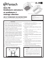
FQ Series
Quiet Exhaust Fans
and Fan-Lights
1. Use this unit in the manner intended by the manufacturer. If you have
any questions, please contact the manufacturer .
2. Before servicing or cleaning unit, switch power off at service panel
and lock the service disconnecting means to prevent power from
being switched on accidentally. When the service disconnecting
means cannot be locked, securely fasten a prominent warning
device, such as a tag, to the service panel.
3. Installation work and electrical wiring must be done by qualified
person(s) in accordance with all applicable codes and standards,
including fire-rated construction.
4. Sufficient air is needed for proper combustion and exhausting of
gases through the flue (chimney) of fuel burning equipment to pre-
vent back drafting. Follow the heating equipment manufacturer’s
guideline and safety standards such as those published by the
National Fire Protection Association (NFPA), and the American
Society for Heating, Refrigeration and Air Conditioning Engineers
(ASHRAE), and the local code authorities.
5. When cutting or drilling into wall or ceiling, do not damage electrical
wiring and other hidden utilities.
6. Ducted fans must always be vented to the outdoors.
7. If this unit is to be installed over a tub or shower, it must be marked
as appropriate for the application and be connected to a GFCI
(Ground Fault Circuit Interrupter) – protected branch circuit.
8. NEVER place a switch where it can be reached from a tub or shower.
9. This fan must be properly grounded.
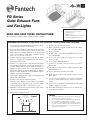
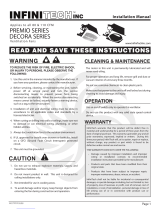
10. Do not use in the cooking area (Figure. 1).
Floor
Cooking
Equipment
Cooking area
Do not install above
or inside this area
45
45
Figure 1
11. Do not block the air intakes or exhaust.
12. Power supply wiring is to be No. 14 AWG wire or larger (suitable
for at least 90°C (190°F) ).
13. Not for use outdoors.
14. For lighted units, use only CFL type T4, 26W lamp and a maxi-
mum 4 W night light .
15. The fan must not be installed in a ceiling with an “R” rating
greater than 40.
16. The fan is type IC (Inherently Protected).
17. To reduce the risk of injury, install the fan at least 7 feet (2.1m)
above the floor.
18. Acceptable for use over a shower or tub when installed in a GFCI
protected branch circuit.
19. The fan should not be turned on or off rapidly.
20. Do not clean the fan with corrosive chemicals or water in excess of
60° C (140° F).
21. If the fan is not operating properly, shut the power off immediately,
and have a certified installer inspect it and have it serviced as
required.
22. These fan must be mounted to structural members that are strong
enough to support the fan’s weight.
23. Do not allow foreign objects to enter the fan; this could result in
electric shock or fan damage.
READ AND SAVE THESE INSTRUCTIONS!
Read carefully all instructions before installing or using this product
FQ Series Fan
FQ Series Fan-Lights
Package Includes:
1 Fantech Exhaust Fan or Fan-Light
5 Mounting Brackets
8 Mounting screws
1 26W CFL Type T4 (Fan-Light models only)
1 4w night light (Fan-Light Models only)
WARNINGS: BEFORE INSTALLATION, TO REDUCE THE RISK OF FIRE, ELECTRIC SHOCK, OR INJURY TO PERSONS, OBSERVE THE FOLLOWING:
CAUTION:
1. For general ventilating use only. Do not use to exhaust haz-
ardous or explosive materials and vapors.
2. This product is designed for installation in flat ceilings only.
Do not install it in a sloping ceiling or in a wall.
3. To avoid motor bearing damage and noisy unbalanced impel-
lers keep construction material / dust from entering the fan.
4. Please read specification label on the product for further
information and requirements.

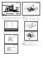
Installation
The unit should only be installed in a ceiling. The size of joists should be at least
2” wide and 4” high . The space between two joists should be 16”. From the above
surface of the suspended ceiling there should be minimum 9” distance to the roof.
(Figure 2) Select the suspension brackets as shown in (Figure 3)
Power supply
protective tube
Housing
Fan outlet
Ceiling joist
Ceiling
Wire box
Wire box cover
Hanger bar
Spacing A on center joist Insert Suspension bracket
16 inches Figure 3-1
24 inches Figure 3-2
Joists
A
Plug-in
Figure 3
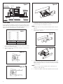
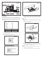
1. Remove the grille by gently squeezing the wire springs and extracting
them from the slots in the housing.
2. Remove the wire box cover and install the 3 brackets on the fan housing.
(Figure. 3-1, Figure. 3-2).
Figure 3-1
Figure 3-2
3. To install the housing in the ceiling, position it between the joists and
extend the brackets to the adjacent joists.. Mark the screw locations (at
the top of the keyhole on each bracket) on the joists.
NOTE:
The bottom edge of the housing should be flush with the bottom of the joist.
(Figure 4)
4. Remove the housing and drive the screws part way into the joists at the
marked locations. (Figure 5)
Power supply
protective tube
Housing
Fan outlet
Ceiling joist
Ceiling
Wire box
Wire box cover
Hanger bar
Spacing A on center joist Insert Suspension bracket
16 inches Figure 3-1
24 inches Figure 3-2
Joists
A
Plug-in
Figure 5
Power supply
protective tube
Housing
Fan outlet
Ceiling joist
Ceiling
Wire box
Wire box cover
Hanger bar
Spacing A on center joist Insert Suspension bracket
16 inches Figure 3-1
24 inches Figure 3-2
Joists
A
Plug-in
Figure 6
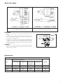
5. Mount the housing using the screws in the joists and then secure them
tightly. Make all the electrical connections in the wire box, per the wiring
diagram, and attach the wire box cover. Attach the discharge duct tightly
onto the fan outlet.
NOTE:
In order for the fan to operate efficiently, keep the discharge duct as
straight as possible. (Figure 6)
6. To complete the installation, install the lamps (if applicable) and mount the grille.
2
Power supply
protective tube
Housing
Fan outlet
Ceiling joist
Ceiling
Wire box
Wire box cover
Hanger bar
Spacing A on center joist Insert Suspension bracket
16 inches Figure 3-1
24 inches Figure 3-2
Joists
A
Plug-in
Figure 4
Power supply
protective tube
Housing
Fan outlet
Ceiling joist
Ceiling
Wire box
Wire box cover
Hanger bar
Spacing A on center joist Insert Suspension bracket
16 inches Figure 3-1
24 inches Figure 3-2
Joists
A
Plug-in
Figure 2

3
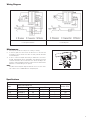
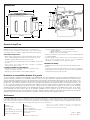
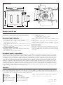
Wiring Diagram
Maintenance
1. Turn the power off and lock it out prior to servicing or cleaning.
2. To clean the grille, first remove it from the fan then use a soft brush and
clean water to remove the dirt. If the dirt is not easily removed, wash with
a neutral detergent.
3. In order to remove the impeller and housing for maintenance, first remove
the light, night light and reflector (if applicable). Then unplug the electrical
connection and remove the 4 screws that secure the fan assembly to the
housing. To clean the impeller and housing, remove the motor and then wash
with water or a neutral detergent, as required.
NOTE:
Keep all electrical components away from water. Do not use corrosive chemi-
cals or water in excess of 60C (140°F) to clean plastic parts.
For Fan-Light Combination For Fan Only Units
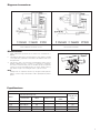
Fan Specifications
Model
Power Consumption (W)
Airflow (CFM)
Power Motor Light (CFL) Night Light
FQ80 120V/60 Hz 25 – – 80
FQ110 120V/60 Hz 30 – – 110
FQ80FL 120V/60 Hz 25 26W 4W 80
FQ110FL 120V/60 Hz 30 26W 4W 110
Specifications
Power supply
protective tube
Housing
Fan outlet
Ceiling joist
Ceiling
Wire box
Wire box cover
Hanger bar
Spacing A on center joist Insert Suspension bracket
16 inches Figure 3-1
24 inches Figure 3-2
Joists
A
Plug-in
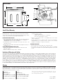
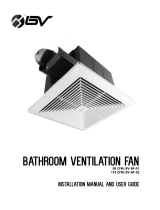
Figure 7

11 7/8''
9 1/2''
3 3/8''
9 1/2''
11''
3 7/8''
8 1/2''
4''
Dimensions
Five (5) Year Warranty
Limitation of Warranty and Liability
Warning
DURING ENTIRE WARRANTY PERIOD:
FANTECH will repair or replace any part which has a factory defect in workman-
ship or material. Product may need to be returned to the Fantech factory, togeth-
er with a copy of the bill of sale and identified with RMA number.
FOR FACTORY RETURN YOU MUST:
• Have a Return Materials Authorization (RMA) number. This may be obtained by
calling FANTECH either in the USA at 1.800.747.1762 or in CANADA at
1.800.565.3548. Please have bill of sale available.
• The RMA number must be clearly written on the outside of the carton, or the
carton will be refused.
• All parts and/or product will be repaired/replaced and shipped back to buyer; no
credit will be issued.
THE FOLLOWING WARRANTIES DO NOT APPLY:
• Damages from shipping, either concealed or visible. Claim must be filed
with freight company.
• Damages resulting from improper wiring or installation.
• Damages or failure caused by acts of God, or resulting from improper
consumer procedures, such as:
1. Improper maintenance
2. Misuse, abuse, abnormal use, or accident, and
3. Incorrect electrical voltage or current.
• Removal or any alteration made on the FANTECH label control number
or date of manufacture.
• Any other warranty, expressed, implied or written, and to any consequential or
incidental damages, loss or property, revenues, or profit, or costs of removal,
installation or reinstallation, for any breach of warranty.
WARRANTY VALIDATION
• The user must keep a copy of the bill of sale to verify purchase date.
• These warranties give you specific legal rights, and are subject to an applicable
consumer protection legislation. You may have additional rights which vary from state
to state.
Fantech, reserves the right to modify, at any time and without notice, any or all
of its products’ features, designs, components and specifications to maintain
their technological leadership position.
Item #: 483431
Rev Date:
062711
United States
10048 Industrial Blvd.
Lenexa, KS 66215
Phone: 800.747.1762; 913.752.6000
Fax: 800.487.9915; 913.752.6466
www.fantech.net; [email protected]
Canada
50 Kanalflakt Way,
Bouctouche, NB E4S 3M5
Phone: 800.565.3548; 506.743.9500
Fax: 877.747.8116; 506.743.9600
www.fantech.net; [email protected]
This warranty does not apply to any FANTECH INC. product or part which has failed as a result of faulty installation or abuse, incorrect electrical
connections or alterations made by others, or use under abnormal operating conditions or misapplication of the product or parts. We will not
approve for payment any repair not made by us or our authorized agent without prior written consent. The foregoing shall constitute our sole and
exclusive warranty and our sole exclusive liability, and is in lieu of any other warranties, whether written, oral, implied or statutory. There are no
warranties which extend beyond the description on the page hereof. In no event, whether as a result of breach of contract, or warranty or alleged
negligence, defect incorrect advice or other causes, shall FANTECH be liable for special or consequential damages, including, but not limited to,
loss of profits or revenue, loss of use of equipment or any other associated equipment, cost of capital, cost of substitute equipment, facilities or
services, downtime costs, or claims of customers of purchase for such damages. FANTECH neither assumes or authorizes any person to assume
for it any other liability in connection with the sale of product(s) or part(s). Some jurisdictions do not allow the exclusion or limitation of incidental
or consequential damages so the above limitations and exclusions may not apply to you.
FANTECH, INC. products are designed and manufactured to provide reliable performance, but they are not guaranteed to be 100% free from defects. Even reliable
products will experience occasional failures and this possibility should be recognized by the user. If these products are used in a life support ventilation system where
failure could result in loss or injury, the user should provide adequate backup ventilation, supplementary natural ventilation, failure alarm system, or acknowledge
willingness to accept the risk of such loss or injury.
Page is loading ...
Page is loading ...
Page is loading ...
Page is loading ...
Page is loading ...
Page is loading ...
Page is loading ...
Page is loading ...
-
 1
1
-
 2
2
-
 3
3
-
 4
4
-
 5
5
-
 6
6
-
 7
7
-
 8
8
-
 9
9
-
 10
10
-
 11
11
-
 12
12


Fantech FQ110 Instructions Manual
- Category
- Household fans
- Type
- Instructions Manual
Ask a question and I''ll find the answer in the document
Finding information in a document is now easier with AI
in other languages
- français: Fantech FQ110
- español: Fantech FQ110
Related papers
-
Fantech FQ 110 Installation guide
-
-
-
-
-
-
-
-
-
Other documents
-
Aero Pure SBF110 G5 W Installation guide
-
 infinitech DECORA 110 CFM Installation guide
-
Broan QTXE110150DC Installation guide
-
Broan QTXE110150DC Installation guide
-
Broan QTXE110150DCL Installation guide
-
-
 BV BV-BF-02 Installation guide
-
NuTone 686 Installation guide
-
-

