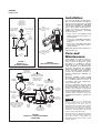
Tyco RC-1 is designed for use in wet pipe sprinkler systems that are subject to pressure variations. It prevents false alarms by filling up when the water flow through the Inlet Restriction exceeds the flow out through the Outlet Restriction. This activates a Water Motor Alarm and/or Pressure Alarm Switch, which continue to operate as long as the Waterway Clapper remains open. When the Clapper closes, water in the alarm lines automatically drains out, further reducing the possibility of a false alarm.
Tyco RC-1 is designed for use in wet pipe sprinkler systems that are subject to pressure variations. It prevents false alarms by filling up when the water flow through the Inlet Restriction exceeds the flow out through the Outlet Restriction. This activates a Water Motor Alarm and/or Pressure Alarm Switch, which continue to operate as long as the Waterway Clapper remains open. When the Clapper closes, water in the alarm lines automatically drains out, further reducing the possibility of a false alarm.


-
 1
1
-
 2
2
-
 3
3
-
 4
4


Tyco RC-1 is designed for use in wet pipe sprinkler systems that are subject to pressure variations. It prevents false alarms by filling up when the water flow through the Inlet Restriction exceeds the flow out through the Outlet Restriction. This activates a Water Motor Alarm and/or Pressure Alarm Switch, which continue to operate as long as the Waterway Clapper remains open. When the Clapper closes, water in the alarm lines automatically drains out, further reducing the possibility of a false alarm.
Ask a question and I''ll find the answer in the document
Finding information in a document is now easier with AI
Related papers
Other documents
-
Potter VS-SP Vane Type Waterflow Alarm Switch Small Pipe Owner's manual
-
Watts 77S Installation guide
-
Johnson Controls Tyco DV-5a Series User manual
-
-
-
Victaulic Series 713 Swing Check Valve Clapper Replacement Kit Operating instructions
-
-
-
-
System Sensor WFDNFT User manual