Mitsubishi Electric MR-JN-20A User manual

Type
User manual
SH(NA)030086ENG-D(1906)MEEPrinted in Japan Specifications are subject to change without notice.
MODEL
MODEL
CODE
General-Purpose AC Servo
MODEL (Servo Amplifier)
MR-JN-A
General-Purpose Interface Servo Amplifier
JN Series
HEAD OFFICE: TOKYO BLDG MARUNOUCHI TOKYO 100-8310
JN Series MR-JN-A Instruction Manual
D
D
MODEL (Servo Motor)
HF-KN
HF-KPG1/G5/G7
HG-KRG1/G5/G7
INSTRUCTION MANUAL
A - 1
Safety Instructions
Please read the instructions carefully before using the equipment.
Be sure to read through this Instruction Manual, Installation guide and appended documents carefully before
using the equipment. For your protection, do not install, operate, inspect or perform maintenance procedures
until you have a full knowledge of the equipment and the safety information and instructions.
In this Instruction Manual, the safety instruction levels are classified into "WARNING" and "CAUTION".
WARNING
Indicates that incorrect handling may cause hazardous conditions,
resulting in death or severe injury.
CAUTION
Indicates that incorrect handling may cause hazardous conditions,
resulting in medium or slight injury to personnel or may cause physical
damage.
Note that the
CAUTION level may lead to a serious consequence according to conditions. Please follow
the instructions of both levels because they are important to personnel safety.
What must not be done and what must be done are indicated by the following diagrammatic symbols.
: Indicates what must not be done. For example, "No Fire" is indicated by .
: Indicates what must be done. For example, grounding is indicated by .
In this Instruction Manual, instructions at a lower level than the above, instructions for other functions, and so on
are classified into "POINT".
After reading this Instruction Manual, always keep it accessible to the operator.
A - 2
1. To prevent electric shock, note the following
WARNING
Before wiring, be sure to turn off the power, wait for 15 minutes or longer, and then make sure that the
charge lamp is off to prevent an electric shock. In addition, always confirm if the charge lamp is off or not
from the front of the servo amplifier.
Ground the servo amplifier and the servo motor securely.
Only qualified personnel should attempt wiring and inspection.
Wire the servo amplifier and the servo motor after installation is complete to prevent an electric shock.
Do not operate the switches with wet hands as it may cause an electric shock.
Do not damage, stress excessively, place heavy objects or pinch the cable to prevent an electric shock.
To prevent an electric shock, always connect the protective earth (PE) terminal (terminal marked ) of
the servo amplifier with the protective earth (PE) of the control box.
When using an earth-leakage current breaker (RCD), select the type B.
To avoid an electric shock, insulate the connections of the power supply terminals.
2. To prevent fire, note the following
CAUTION
Install the servo amplifier, the servo motor and the regenerative option on incombustible material. Installing
them directly or close to combustibles may cause a fire.
Be sure to connect a magnetic contactor between the power supply and the main circuit power supply
(L1/L2) of the servo amplifier, in order to configure a circuit that shuts off the power supply by the magnetic
contactor. If a magnetic contactor is not connected, a continuous flow of a large current may cause a fire
when the servo amplifier malfunctions.
When using a regenerative resistor, configure a circuit that shuts off the power if abnormality is found.
Otherwise, the regenerative resistor may overheat, causing a fire due to a regenerative transistor fault.
When using a regenerative option, remove the built-in regenerative resistor and its wiring from the servo
amplifier.
Provide an adequate protection to prevent conductive matters such as screws or metal pieces or
combustible matters such as oil from entering the servo amplifier and the servo motor.
Always connect a molded-case circuit breaker to the power supply of the servo amplifier.
3. To prevent injury, note the following
CAUTION
Do not apply voltage other than specified in this Instruction Manual to each terminal as it may cause burst,
damage, etc.
Connect the wires to correct terminals to prevent burst, damage, etc.
Ensure that polarity ( , ) is correct. Otherwise, a burst, damage, etc. may occur.
The servo amplifier heat sink, the regenerative option, the servo motor can be very hot during power-on
and for some time after power-off, and it may result burns or damages to parts (cables, etc.) Take
measures, e.g. provide covers, to prevent accidental contact of hands and parts with them.
Never touch the rotating parts of the servo motor during operation as it may cause injury.
A - 3
4. Additional instructions
The following instructions should also be fully noted. Incorrect handling may cause a fault, injury, electric shock,
etc.
(1) Transportation and installation
CAUTION
Carry the products in a suitable way according to their weights.
Do not stack the product packages exceeding the maximum number specified on the package.
Do not hold the lead of the built-in regenerative resistor, the cables, or the connectors when carrying the
servo amplifier. Otherwise, it may drop.
Do not hold the cable, the shaft or the encoder when carrying the servo motor.
Install the equipment on a weight-bearing place in accordance with this Instruction Manual.
Do not get on or place heavy objects on the equipment.
Install the equipment in the specified direction. Improper installation causes oil leakage, leading to a fire
and malfunction.
Leave specified clearances between the servo amplifier and inner wall of the control box or other
equipment.
Do not block the intake/exhaust ports of the servo amplifier. Otherwise, a fault may occur.
Do not install or operate a servo amplifier and a servo motor which are damaged or have any part missing.
Do not drop or shock the servo amplifier or the servo motor as they are precision equipment.
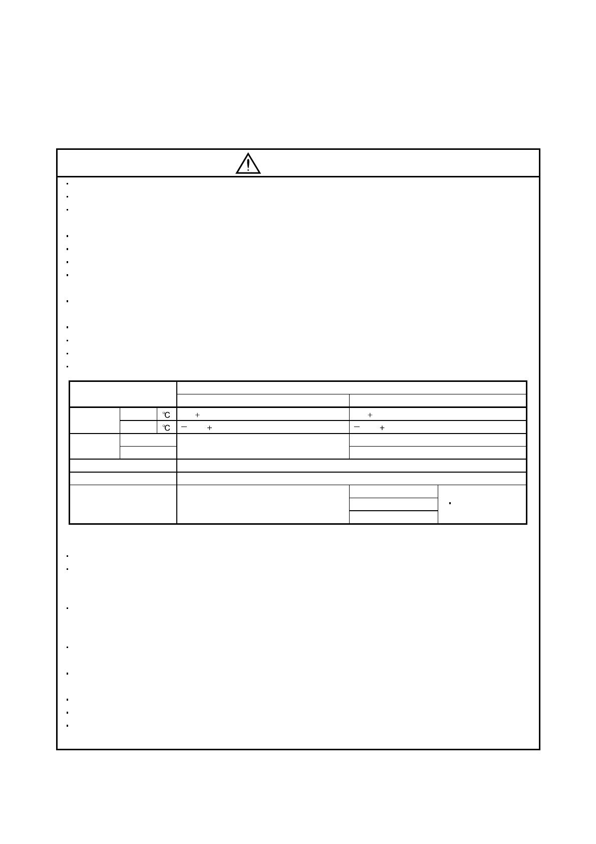
When storing the equipment, please fulfill the following environmental conditions.
Item
Environmental
Servo amplifier Servo motor
Ambient
temperature
Operation [ ] 0 to 55 (non-freezing) 0 to 40 (non-freezing)
Storage [ ] 20 to 65 (non-freezing) 15 to 70 (non-freezing)
Ambient
humidity
Operation
5%RH to 90%RH (non-condensing)
10%RH to 80%RH (non-condensing)
Storage 10%RH to 90%RH (non-condensing)
Ambience Indoors (no direct sunlight) Free from corrosive gas, flammable gas, oil mist, dust and dirt
Altitude Max. 1000m (3280 ft)
Vibration resistance
5.9 m/s
2
, 10 to 55Hz
(directions of X, Y, and Z axes)
HF-KN Series
X
Y: 49m/s
2
HF-KP Series (Note)
HG-KR series (Note)
Note. For the standard servo motor (without reduction gear.)
Couple the servo motor to a machine securely. Insecure coupling may cause the servo motor to come off.
Be sure to measure the motor vibration level with the servo motor mounted to the machine when checking
the vibration level. A great vibration may cause the early damage of a bearing, encoder, brake, and
reduction gear. The great vibration may also cause the poor connector connection or bolt looseness.
For the gain adjustment at the equipment startup, check the torque waveform and the speed waveform by
using a measurement device, and then check that no vibration occurs. If the vibration occurs due to high
gain, the vibration may cause the early damage of the servo motor.
Take safety measures, e.g. provide covers, to prevent accidental access to the rotating parts of the servo
motor during operation.
Never hit the servo motor or shaft, especially when coupling the servo motor to a machine as it may
damage the encoder.
Do not apply load exceeding the permissible load as it may break the shaft.
When the equipment has been stored for an extended period of time, contact your local sales office.
When handling the servo amplifier, be careful with the edged parts such as the corners of the servo
amplifier.
A - 4
CAUTION
The servo amplifier must be installed in the metal cabinet.
When fumigants that contain halogen materials such as fluorine, chlorine, bromine, and iodine are used for
disinfecting and protecting wooden packaging from insects, they cause malfunction when entering our
products. Please take necessary precautions to ensure that remaining materials from fumigant do not
enter our products, or treat packaging with methods other than fumigation (heat method). Additionally,
disinfect and protect wood from insects before packing products.
(2) Wiring
CAUTION
Before unplugging CNP1 connector from the servo amplifier, disconnect the lead of the built-in
regenerative resistor from CNP1 connector first.
Wire the equipment correctly and securely. Improper wiring may cause unexpected operation.
Do not install a power capacitor, a surge killer or a radio noise filter (optional FR-BIF) between the servo
motor and the servo amplifier.
Connect the wires to the correct phase terminals (U, V, W) of the servo amplifier and the servo motor. Not
doing so may cause unexpected operation.
Connect the servo amplifier power output (U/V/W) to the servo motor power input (U/V/W) directly. Do not
install a magnetic contactor, etc. between the servo amplifier and the servo motor.
U
Servo motor
M
V
W
U
V
W
U
Servo motor
MV
W
U
V
W
Servo amplifier
Servo amplifier
Do not connect AC power supply directly to the servo motor. Otherwise, a fault may occur.
Install a surge absorbing diode on the DC relay designed for control output signal in the specified
direction. Improper installation of the surge absorbing diode may cause the servo amplifier to malfunction
such that the signals are not output, and emergency stop and other safety circuits are inoperable.
DOCOM
Control output
signal
DICOM
24VDC
Servo amplifier
RA
Sink output
interface
DOCOM
Control output
signal
DICOM
24VDC
Servo amplifier
RA
Source output
interface
Configure a circuit to turn off EM1 when the main circuit power supply is turned off to prevent an
unexpected restart of the servo amplifier.
(3) Test run adjustment
CAUTION
Check and adjust the parameter setting before operation. Improper settings may cause some machines
to perform unexpected operation.
Never adjust or change the parameter values extremely as it will make operation unstable.
A - 5
(4) Usage
CAUTION
Configure an external emergency stop circuit in order to stop the operation immediately and shut off the
power.
Do not disassemble or repair the equipment.
If an alarm is reset while the operation signal is input to the servo amplifier, the equipment starts
suddenly. Be sure that the operation signal is off before resetting the alarm to prevent an accident.
Do not modify the equipment.
Electromagnetic interference from the servo amplifier may affect the surrounding electronic equipment.
Minimize the influence of the electromagnetic interference by using a noise filter, etc.
Toxic gases may be generated by burning or disassembling the servo amplifier. Do not burn or
disassemble the servo amplifier.
Use the servo amplifier with the specified servo motor.
The electromagnetic brake on the servo motor is designed to hold the motor shaft and should not be used
for ordinary braking.
For such reasons as service life and mechanical structure (e.g. where a ball screw and the servo motor
are coupled via a timing belt), the electromagnetic brake may not hold the motor shaft. To ensure safety,
install a stopper on the machine side.
(5) Corrective actions
CAUTION
Ensure safety by confirming the power off, etc. before performing corrective actions. Otherwise, it may
cause an accident.
When it is assumed that a hazardous condition may take place at the occur due to a power failure or a
product fault, use a servo motor with an electromagnetic brake or provide an external brake mechanism
for the purpose of prevention.
Configure the electromagnetic brake operation circuit which interlocks with an external emergency stop
switch.
SON RA
Servo motor
Electromagnetic brake
B
Shut off the servo motor when the Servo-on
(SON), the Malfunction (ALM), or the
Electromagnetic brake interlock (MBR)
are turned OFF.
24VDC
Circuit must be opened with the
emergency stop switch.
When an alarm occurs, remove its cause. Then, ensure safety and reset the alarm before restarting
operation.
Provide an adequate protection to prevent unexpected restart after an instantaneous power failure.
A - 6
(6) Storing of servo motor
CAUTION
Note the following points when storing the servo motor for an extended period of time (guideline: three or
more months).
Be sure to store the servo motor indoors in a clean and dry place.
If it is stored in a dusty or damp place, make adequate provision, e.g. cover the whole product.
If the insulation resistance of the winding decreases, reexamine the storage method.
Though the servo motor is rust-proofed before shipment using paint or rust prevention oil, rust may be
produced depending on the storage conditions or storage period. If the servo motor is to be stored for
longer than six months, apply rust prevention oil again especially to the machined surfaces of the shaft,
etc.
Before using the servo motor that has been stored for an extended period of time, hand-turn the servo
motor output shaft to confirm that nothing is wrong with the servo motor. (For the servo motor with an
electromagnetic brake, turn ON the power supply of the electromagnetic brake, first. Then, release the
electromagnetic brake before hand-turn.)
When the equipment has been stored for an extended period of time, contact your local sales office.
(7) Maintenance, inspection and parts replacement
CAUTION
Make sure that the emergency stop circuit operates properly such that an operation can be stopped
immediately and a power is shut off by the emergency stop switch.
It is recommended that the servo amplifier be replaced every 10 years when it is used in general
environment.
(8) General instruction
To illustrate details, the equipment in the diagrams of this Instruction Manual may have been drawn
without covers and safety guards. When the equipment is operated, the covers and safety guards must
be installed as specified. Operation must be performed in accordance with this Instruction Manual.
A - 7
About processing of waste
When you discard converter unit, servo amplifier, servo motor, battery (primary battery), and other option
articles, please follow the law of each country (area).
FOR MAXIMUM SAFETY
These products have been manufactured as a general-purpose part for general industries, and have not
been designed or manufactured to be incorporated in a device or system used in purposes related to
human life.
Before using the products for special purposes such as nuclear power, electric power, aerospace,
medicine, passenger movement vehicles or under water relays, contact Mitsubishi Electric.
These products have been manufactured under strict quality control. However, when installing the product
where major accidents or losses could occur if the product fails, install appropriate backup or failsafe
functions in the system.
EEP-ROM life
The number of write times to the EEP-ROM, which stores parameter settings, etc., is limited to 100,000. If
the total number of the following operations exceeds 100,000, the converter unit, servo amplifier (drive unit)
and/or converter unit may fail when the EEP-ROM reaches the end of its useful life.
Write to the EEP-ROM due to parameter setting changes
Write to the EEP-ROM due to device changes
Write to the EEP-ROM due to point table changes
Write to the EEP-ROM due to program changes
Write to the EEP-ROM due to data records with drive recorder
Precautions for Choosing the Products
Mitsubishi Electric will not be held liable for damage caused by factors found not to be the cause of
Mitsubishi Electric; machine damage or lost profits caused by faults in the Mitsubishi Electric products;
damage, secondary damage, accident compensation caused by special factors unpredictable by Mitsubishi
Electric; damages to products other than Mitsubishi Electric products; and to other duties.
COMPLIANCE WITH EC DIRECTIVES
Refer to appendix 7 for the compliance with EC directives.
CONFORMANCE WITH UL/CSA STANDARD
Refer to appendix 8 for the conformance with UL/CSA standard.
A - 8
<<About the manuals>>
Relevant manuals
Manual name Manual No.
MELSERVO-JN Series Instructions and Cautions for Safe Use of AC Servos
(Enclosed in servo amplifier.)
IB(NA)0300157
QUICK INSTALLATION GUIDE L(NA)03052ENG
MELSERVO Servo Motor Instruction Manual Vol.2 SH(NA)030041ENG
MELSERVO Servo Motor Instruction Manual Vol.3 SH(NA)030113ENG
EMC Installation Guidelines IB(NA)67310
<<About the wires used for wiring>>
Wiring wires mentioned in this instruction manual are selected based on the ambient temperature of 40
(104
).
<<U.S. customary units>>
U.S. customary units are not shown in this manual. Convert the values if necessary according to the
following table.
Quantity SI (metric) unit U.S. customary unit
Mass 1 [kg] 2.2046 [lb]
Length 1 [mm] 0.03937 [inch]
Torque 1 [N•m] 141.6 [oz•inch]
Moment of inertia 1 [(× 10
-4
kg•m
2
)] 5.4675 [oz•inch
2
]
Load (thrust load/axial load) 1 [N] 0.2248 [lbf]
Temperature N [°C] × 9/5 + 32 N [°F]
- 1 -
Introduction
Introduction
The Mitsubishi Electric MELSERVO-JN series general-purpose AC servo is based on the MELSERVO-J3
series, and retains its high performance, with some limitations in functions. For details of functions,
performance and specifications of the MELSERVO-JN series, refer to chapters 1 to 13 and appendices of this
Instruction Manual. This section describes the how-to (startup, actual operation, and others) for users who use
the MELSERVO-JN series AC servo for the first time.
CAUTION
The lead of the built-in regenerative resistor is connected between P and C
terminals on the servo amplifier power supply connectors (CNP1) of the MR-JN-
20A(1)/40A. When taking the servo amplifier out from the shipping box, do not hold
the lead of the built-in regenerative resistor.
Unpack the product and check the rating plate to see if the servo motor and servo amplifier are as you ordered.
(1) Servo amplifier
Packaged product Quantity
Servo amplifier 1
Servo amplifier power supply connectors for CNP1 and CNP 2 1 each
MELSERVO-JN series
Instructions and Cautions for Safe Use of AC Servos
1
(2) Servo motor
Packaged product Quantity
Servo motor 1
Instructions and Cautions for Safe Use of AC Servos (Motor) 1
- 2 -
Introduction
1. Operation and setting
Operation and settings of the servo amplifier are easily performed only on the display section (3-digit, 7-
segment LED) and on the operation section (four pushbuttons and one-touch tuning button) located on the
front panel of the servo amplifier.
AUTO
MODE
UP/DOWN
SET
Scrolls the display and data.
Determines the display and
data, and clears data.
Changes the display mode
and switches the upper/lower.
Executes the one-touch
tuning.
(1) One-touch tuning function (refer to section 6.1)
Gain and filter adjustment of the servo is easily made by the AUTO button located on the front panel of the
servo amplifier.
(2) Status display, diagnosis, and parameter setting (refer to chapter 5)
The servo amplifier status display (cumulative feedback pulses, servo motor speed, and others), diagnosis
(servo operation-ready complete status, external I/O signal ON/OFF, test operation), point table settings
and parameter settings can be easily performed by the MODE, SET, UP and DOWN buttons located on the
front panel of the servo amplifier.
- 3 -
Introduction
2. Startup
When switching the power on for the first time, follow the startup procedure below.
I/O signal wiring check during
power-on
Surrounding environment
check
Power-on of the control circuit
power supply
Visual wiring check
Parameter setting
Power-on of the main circuit
power supply
Operation confirmation before
actual operation
One-touch tuning
Actual operation
Stop
Refer to (1) in this section.
Check the surrounding environment (cable routing and
impurity such as wire offcuts or metallic dust) of the servo
amplifier and the servo motor.
Refer to (2) (a) in this section.
Refer to (3) in this section.
Refer to (4) in this section.
Refer to (2) (a) in this section.
Refer to (5) in this section.
Refer to (6) in this section.
Refer to (7) in this section.
When switching the power off, follow (2) (b) in this section.
- 4 -
Introduction
(1) Visual wiring check
Before switching on the main circuit and control circuit power supplies, check the following items.
Power supply system wiring
The power supplied to the power input terminals (L1, L2, +24V, 0V) of the servo amplifier should satisfy
the defined specifications. (Refer to section 1.3.)
Connection of servo amplifier and servo motor
The servo motor power supply terminals (U, V, W) of the servo amplifier should match in phase with the
power input terminals (U, V, W) of the servo motor.
Servo amplifier Servo motor
M
U
V
W
U
V
W
The power supplied to the servo amplifier should not be connected to the servo motor power supply
terminals (U, V, W). The connected servo amplifier and servo motor will be damaged.
M
U
V
W
U
V
W
L
1
L
2
Servo amplifier
Servo motor
The earth terminal of the servo motor should be connected to the PE terminal of the servo amplifier.
Servo amplifier Servo motor
M
When regenerative option is used
The built-in regenerative resistor and its wirings should be removed from the servo amplifier.
The regenerative option should be connected to P and C terminals.
A twisted cable should be used. (Refer to section 11.2 (4).)
I/O signal wiring
The power supplied to CN1 connector (DICOM and DOCOM) of the servo amplifier should satisfy the
defined specifications. (Refer to section 1.3.)
SD and DOCOM of CN1 connector should not be shorted.
Servo amplifier
DOCOM
SD
CN1
- 5 -
Introduction
(2) Power on and off procedures
(a) Power-on
Switch the power on in the following procedure. Always follow this procedure at power-on.
1) Turn off the servo-on (SON).
2) Make sure that command and start signal from the controller are not input.
3) Switch on the control circuit power supply.
At power-on, "888" appears instantaneously, but it is not an error.
In the position control mode, data is displayed in 2[s] or later after displaying "CL" (cumulative
feedback pulses in pulse unit) (initial value), or by pressing the "MODE", "UP" or "DOWN" button.
Displayed contents differ depending on each control mode. Refer to section 5.3 for details.
4) Switch on the main circuit power supply.
(b) Power-off
1) Make sure that command and start signal from the controller are not input.
2) Turn off the servo-on (SON).
3) Switch off the main circuit power supply.
4) Switch off the control circuit power supply.
(3) I/O signal wiring check during the energization
Input signal wiring confirmation
On/off status of the input signals of CN1 connector can be checked using the external I/O signal display.
By using this function, input signal wiring can be checked. (Refer to section 5.8.)
Output signal wiring confirmation
Output signals of CN1 connector can be turned on/off forcibly using the DO output. By using this function,
output signal wiring can be checked. (Refer to section 5.9.)
(4) Parameter setting
POINT
Some parameters are made valid when power is switched off, then on after
setting. Refer to chapter 4 for details.
For the positioning mode, refer to section 13.7.
Set the parameters as necessary, such as selecting the control mode and the regenerative option.
In the position control mode, the servo amplifier can be used just by changing the basic setting parameters
(parameter No. PA
) mainly.
As necessary, set the gain/filter parameters (parameter No. PB ), the extension setting parameters
(parameter No. PC
) and the I/O setting parameters (parameter No. PD ).
For the internal speed control mode and the internal torque control mode, refer to chapter 4.
- 6 -
Introduction
The following shows the main parameters, which must be changed, among parameter No. PA
.
PA01 Selection of control mode (refer to section 4.1.3)
Select the control mode of the servo amplifier, and whether to enable or not the one-touch tuning function.
Selection of control mode
0: Position control mode
1: Position control mode and internal speed control mode
2: Internal speed control mode
3: Internal speed control mode and in ternal
torque
control mode
4: Internal torque control mode
5: Internal torque control mode and position control mode
6: Positioning mode (point table method)
7: Positioning mode (program method)
0
Parameter No. PA01
One-touch tuning function selection
0: Valid
1: Invalid
When this parameter is set to "1", the one-touch tuning is ignored.
PA02 Selection of regenerative option (refer to section 4.1.4)
Set this parameter when using the regenerative option.
Selection of regenerative option
00: Regenerative option is not used.
For servo amplifier of 100W, regenerative resistor is not used.
For servo amplifier of 200 to 400W, built-in regenerative resistor is
used.
02: MR-RB032
03: MR-RB12
0
Parameter No. PA02
PA05 Number of command input pulses per servo motor revolution (refer to section 4.1.6)
Set the number of command input pulses necessary to rotate the servo motor one turn.
When "100 (10000[pulse/rev])" (initial value) is set to parameter No. PA05, the servo motor rotates one turn
by inputting 1000 pulses of the command pulse to the servo amplifier. When "0" is set to parameter No.
PA05, the servo motor rotates one turn by inputting the command pulse of servo motor resolution to the
servo amplifier.
Parameter No. PA05
setting
Description
0 Servo motor resolution [pulse/rev]
100 to 500
Number of command input pulses necessary to rotate the servo motor one
turn [
100 pulse/rev]
Command
pulses
Deviation
counter
Value converted to the number of
command input pulses per revolution
(FBP)
Servo motor
Encoder
M
CDV
CMX
FBP conversion
(Note 1)
Electronic gear
Parameter No. PA05
(Note 2)
Note 1. This process converts the number of pulses required to rotate the servo motor one turn to the value set in parameter No. PA05.
2. Electric gear numerator and denominator can be set by parameters No. PA06 and PA07. (Refer to section 4.1.7.)
- 7 -
Introduction
PA13 Selection of command input pulse form (refer to section 4.1.11)
Select the input form of the pulse train input signal. Command pulses may be input in any of three different
forms, for which positive or negative logic can be chosen.
Arrow
or in the table indicates the timing of importing a pulse train. A- and B-phase pulse trains
are imported after being multiplied by 4.
Forward rotation
pulse train
Reverse rotation
pulse train
Selection of command input pulse form
Parameter No. PA13
Setting
00
01
Pulse train input filter selection
Pulse train form
Forward rotation command
Reverse rotation command
Signed pulse
train
A-phase pulse
train
B-phase pulse
train
Forward rotation
pulse train
Reverse rotation
pulse train
Signed pulse
train
A-phase pulse
train
B-phase pulse
train
02
10
12
11
Positive logic
NP
PP
PP
L
H
NP
PP
NP
NP
PP
L
H
PP
NP
PP
NP
Setting
Command pulse frequency
0 1Mpps or less
1500kpps or less
2200kpps or less
Negative logic
POINT
The noise tolerance can be enhanced by setting parameter No. PA13 to "1 "
when the command pulse frequency is 500kpps or less or "2
" when
200kpps or less.
- 8 -
Introduction
PA14 Selection of servo motor rotation direction (refer to section 4.1.12)
Select servo motor rotation direction relative to the input pulse train.
Parameter No. PA14
setting
Servo motor rotation direction
When forward rotation pulse is input When reverse rotation pulse is input
0 CCW CW
1 CW CCW
Forward rotation (CCW)
Reverse rotation (CW)
(5) Operation confirmation before actual operation
Before starting actual operation, perform JOG operation to make sure that the machine operates properly.
MR-JN can perform the JOG operation in the test operation mode on the operation section (four
pushbuttons). (Refer to section 5.10.)
JOG operation in the test operation
mode
(Servo motor alone)
(a) Confirm that the servo amplifier and servo motor operate properly.
With the servo motor disconnected from the machine, use the test
operation mode (JOG operation) at the slowest speed and check
whether the servo motor rotates correctly.
Operation by commands from the
controller
(Servo motor and machine are
connected)
(b) Confirm that the servo motor rotates correctly at the slowest speed
under the commands from the controller.
Make sure that the servo motor rotates in the following procedure.
1) Switch on the forced stop (EM1) and servo-on (SON). When the
servo amplifier is in a servo-on status, the ready (RD) switches
on.
2) Switch on the forward rotation stroke end (LSP) and the reverse
rotation stroke end (LSN).
3) In the position control mode, when command pulses are input
from the controller, the servo motor starts rotating. Give a low
speed command at first and check the operation direction, etc.
of the servo motor. If the servo motor does not rotate in the
intended direction, check the input signal.
4) After checking that the machine operates properly, perform the
automatic operation by the program of the controller to check for
any problem with the operation.
- 9 -
Introduction
(6) One-touch tuning
Just by pressing the "AUTO" button on the front panel of the servo amplifier during operation, the gain/filter
is easily adjusted.
(Refer to section 6.1.)
Operation
Shift to the one-touch tuning
mode
Startup of system
Selection of the response
mode
Execution of the one-touch
tuning
One-touch tuning complete
Rotate the servo motor by a command device, etc.
(The one-touch tuning cannot be performed if the servo
motor is not operating.)
Press the "AUTO" button for 3[s] or longer while the servo
motor is rotating. The display changes to "
", and the
mode shifts to the one-touch tuning mode.
Press the "UP" or the "DOWN" button while "
" is
displayed to select the response mode. (Refer to (1) in
section 6.1.2.)
Start the one-touch tuning by pressing the "AUTO" button.
The progress of the one-touch tuning is displayed in
percentage.
0% 100%
When the one-touch tuning is completed properly,
"
" is displayed and the gain/filter is automatically
adjusted.
POINT
For the fine adjustment after the one-touch tuning, refer to section 6.4.
- 10 -
Introduction
(7) Stop
In any of the following statuses, the servo amplifier interrupts and stops the operation of the servo motor.
Refer to section 3.11 for the servo motor with an electromagnetic brake.
(a) Servo-on (SON) OFF
The base circuit is shut off and the servo motor coasts.
(b) Alarm occurrence
When an alarm occurs, the base circuit is shut off and the dynamic brake activates to stop the servo
motor immediately.
(c) Forced stop (EM1) OFF
The base circuit is shut off and the dynamic brake activates to stop the servo motor immediately. Servo
forced stop warning alarm (E6.1) occurs.
(d) Forward rotation stroke end (LSP) or reverse rotation stroke end (LSN) OFF
Position control mode: Droop pluses are cleared, and the servo motor shaft is locked. The servo motor
can rotate in an opposite direction.
Internal speed control mode: The servo motor stops immediately, and the shaft is locked. The servo
motor can rotate in an opposite direction.
(e) Simultaneous ON or simultaneous OFF of forward rotation start (ST1) and reverse rotation start (ST2)
In internal speed control mode: The servo motor decelerates to a stop.
In positioning mode: The servo motor decelerates to a stop after JOG operation.
(f) Simultaneous ON or simultaneous OFF of forward rotation selection (RS1) and reverse rotation selection
(RS2) (only in the internal torque control)
The servo motor coasts.
POINT
The forward rotation stroke end (LSP) and reverse rotation stroke end (LSN)
operate as follows.
Assigned to the external input signals: depends on the value set in parameter
No. PD01.
Not assigned to the external input signals: automatically turns on regardless of
the value set in parameter No. PD01.
In the internal torque control mode, the forward rotation stroke end (LSP) and
reverse rotation stroke end (LSN) become invalid. (Refer to section 3.5.)
- 11 -
Introduction
3. Troubleshooting at startup
CAUTION
Never adjust or change the parameter values extremely as it will make operation
unstable.
POINT
You can refer to reasons for servo motor rotation failure, etc. using MR
Configurator.
The following faults may occur at startup. If any of such faults occurs, take the corresponding action.
(1) Troubleshooting
No. Step of occurrence Fault Investigation Possible cause Reference
1 Power on
The 3-digit, 7-segment
LED is not lit.
The 3-digit, 7-segment
LED blinks.
Not improved even if CN1, CN2
and CN3 connectors are
disconnected.
1. Power supply voltage fault
2. Servo amplifier is faulty.
Improved when CN1 connector is
disconnected.
Power supply of CN1 cabling is
shorted.
Improved when CN2 connector is
disconnected.
1. Power supply of encoder
cabling is shorted.
2. Encoder is faulty.
Improved when CN3 connector is
disconnected.
Power supply of CN3 cabling is
shorted.
Alarm occurs. Remove cause. Section
8.2
Digital output ALM
occurs. The 3-digit,
7-segment LED does not
display the alarm.
Check the ON/OFF status of the
output signal on the external I/O
signal display (refer to section
5.8).
Wiring mistake.
The polarity of the digital output
circuit diode is not correct.
Section
3.8.2
2 Switch on servo-on
(SON).
Alarm occurs. Remove cause. Section
8.2
Servo motor shaft is
free.
Check the followings.
1. Check the display to see if the
servo amplifier is ready to
operate.
2. Check the external I/O signal
display (refer to section 5.8) to
see if the servo-on (SON) is ON.
1. Servo-on (SON) is not input.
(Wiring mistake)
2. The interface power supply
(24VDC) is not supplied.
Section
5.8
3 Input command
pulse.
(Test operation)
(In the position
control mode)
Servo motor does not
rotate.
Check the cumulative command
pulses on the status display or on
MR Configurator.
1. Wiring mistake.
(a) For open collector pulse train
input, 24VDC power is not
supplied to OPC.
(b) LSP and LSN are not on.
(c) Wiring mistake.
The polarity of the digital output
circuit diode is not correct.
2. No pulses are input.
3. Electromagnetic brake operates.
Section
3.8.2
Section
3.11
Section
4.1.11
Section
5.3
Check if the ready (RD) is ON.
Check the set value of parameter
No.PA13 (command input pulse
form).
Check if the electromagnetic
brake interlock (MBR) is ON.
Check the ON/OFF status of the
output signal on the external I/O
signal display (refer to section
5.8).
Wiring mistake.
The polarity of the digital output
circuit diode is not correct.
Section
3.8.2
  • Page 1 1
  • Page 2 2
  • Page 3 3
  • Page 4 4
  • Page 5 5
  • Page 6 6
  • Page 7 7
  • Page 8 8
  • Page 9 9
  • Page 10 10
  • Page 11 11
  • Page 12 12
  • Page 13 13
  • Page 14 14
  • Page 15 15
  • Page 16 16
  • Page 17 17
  • Page 18 18
  • Page 19 19
  • Page 20 20
  • Page 21 21
  • Page 22 22
  • Page 23 23
  • Page 24 24
  • Page 25 25
  • Page 26 26
  • Page 27 27
  • Page 28 28
  • Page 29 29
  • Page 30 30
  • Page 31 31
  • Page 32 32
  • Page 33 33
  • Page 34 34
  • Page 35 35
  • Page 36 36
  • Page 37 37
  • Page 38 38
  • Page 39 39
  • Page 40 40
  • Page 41 41
  • Page 42 42
  • Page 43 43
  • Page 44 44
  • Page 45 45
  • Page 46 46
  • Page 47 47
  • Page 48 48
  • Page 49 49
  • Page 50 50
  • Page 51 51
  • Page 52 52
  • Page 53 53
  • Page 54 54
  • Page 55 55
  • Page 56 56
  • Page 57 57
  • Page 58 58
  • Page 59 59
  • Page 60 60
  • Page 61 61
  • Page 62 62
  • Page 63 63
  • Page 64 64
  • Page 65 65
  • Page 66 66
  • Page 67 67
  • Page 68 68
  • Page 69 69
  • Page 70 70
  • Page 71 71
  • Page 72 72
  • Page 73 73
  • Page 74 74
  • Page 75 75
  • Page 76 76
  • Page 77 77
  • Page 78 78
  • Page 79 79
  • Page 80 80
  • Page 81 81
  • Page 82 82
  • Page 83 83
  • Page 84 84
  • Page 85 85
  • Page 86 86
  • Page 87 87
  • Page 88 88
  • Page 89 89
  • Page 90 90
  • Page 91 91
  • Page 92 92
  • Page 93 93
  • Page 94 94
  • Page 95 95
  • Page 96 96
  • Page 97 97
  • Page 98 98
  • Page 99 99
  • Page 100 100
  • Page 101 101
  • Page 102 102
  • Page 103 103
  • Page 104 104
  • Page 105 105
  • Page 106 106
  • Page 107 107
  • Page 108 108
  • Page 109 109
  • Page 110 110
  • Page 111 111
  • Page 112 112
  • Page 113 113
  • Page 114 114
  • Page 115 115
  • Page 116 116
  • Page 117 117
  • Page 118 118
  • Page 119 119
  • Page 120 120
  • Page 121 121
  • Page 122 122
  • Page 123 123
  • Page 124 124
  • Page 125 125
  • Page 126 126
  • Page 127 127
  • Page 128 128
  • Page 129 129
  • Page 130 130
  • Page 131 131
  • Page 132 132
  • Page 133 133
  • Page 134 134
  • Page 135 135
  • Page 136 136
  • Page 137 137
  • Page 138 138
  • Page 139 139
  • Page 140 140
  • Page 141 141
  • Page 142 142
  • Page 143 143
  • Page 144 144
  • Page 145 145
  • Page 146 146
  • Page 147 147
  • Page 148 148
  • Page 149 149
  • Page 150 150
  • Page 151 151
  • Page 152 152
  • Page 153 153
  • Page 154 154
  • Page 155 155
  • Page 156 156
  • Page 157 157
  • Page 158 158
  • Page 159 159
  • Page 160 160
  • Page 161 161
  • Page 162 162
  • Page 163 163
  • Page 164 164
  • Page 165 165
  • Page 166 166
  • Page 167 167
  • Page 168 168
  • Page 169 169
  • Page 170 170
  • Page 171 171
  • Page 172 172
  • Page 173 173
  • Page 174 174
  • Page 175 175
  • Page 176 176
  • Page 177 177
  • Page 178 178
  • Page 179 179
  • Page 180 180
  • Page 181 181
  • Page 182 182
  • Page 183 183
  • Page 184 184
  • Page 185 185
  • Page 186 186
  • Page 187 187
  • Page 188 188
  • Page 189 189
  • Page 190 190
  • Page 191 191
  • Page 192 192
  • Page 193 193
  • Page 194 194
  • Page 195 195
  • Page 196 196
  • Page 197 197
  • Page 198 198
  • Page 199 199
  • Page 200 200
  • Page 201 201
  • Page 202 202
  • Page 203 203
  • Page 204 204
  • Page 205 205
  • Page 206 206
  • Page 207 207
  • Page 208 208
  • Page 209 209
  • Page 210 210
  • Page 211 211
  • Page 212 212
  • Page 213 213
  • Page 214 214
  • Page 215 215
  • Page 216 216
  • Page 217 217
  • Page 218 218
  • Page 219 219
  • Page 220 220
  • Page 221 221
  • Page 222 222
  • Page 223 223
  • Page 224 224
  • Page 225 225
  • Page 226 226
  • Page 227 227
  • Page 228 228
  • Page 229 229
  • Page 230 230
  • Page 231 231
  • Page 232 232
  • Page 233 233
  • Page 234 234
  • Page 235 235
  • Page 236 236
  • Page 237 237
  • Page 238 238
  • Page 239 239
  • Page 240 240
  • Page 241 241
  • Page 242 242
  • Page 243 243
  • Page 244 244
  • Page 245 245
  • Page 246 246
  • Page 247 247
  • Page 248 248
  • Page 249 249
  • Page 250 250
  • Page 251 251
  • Page 252 252
  • Page 253 253
  • Page 254 254
  • Page 255 255
  • Page 256 256
  • Page 257 257
  • Page 258 258
  • Page 259 259
  • Page 260 260
  • Page 261 261
  • Page 262 262
  • Page 263 263
  • Page 264 264
  • Page 265 265
  • Page 266 266
  • Page 267 267
  • Page 268 268
  • Page 269 269
  • Page 270 270
  • Page 271 271
  • Page 272 272
  • Page 273 273
  • Page 274 274
  • Page 275 275
  • Page 276 276
  • Page 277 277
  • Page 278 278
  • Page 279 279
  • Page 280 280
  • Page 281 281
  • Page 282 282
  • Page 283 283
  • Page 284 284
  • Page 285 285
  • Page 286 286
  • Page 287 287
  • Page 288 288
  • Page 289 289
  • Page 290 290
  • Page 291 291
  • Page 292 292
  • Page 293 293
  • Page 294 294
  • Page 295 295
  • Page 296 296
  • Page 297 297
  • Page 298 298
  • Page 299 299
  • Page 300 300
  • Page 301 301
  • Page 302 302
  • Page 303 303
  • Page 304 304
  • Page 305 305
  • Page 306 306
  • Page 307 307
  • Page 308 308
  • Page 309 309
  • Page 310 310
  • Page 311 311
  • Page 312 312
  • Page 313 313
  • Page 314 314
  • Page 315 315
  • Page 316 316
  • Page 317 317
  • Page 318 318
  • Page 319 319
  • Page 320 320
  • Page 321 321
  • Page 322 322
  • Page 323 323
  • Page 324 324
  • Page 325 325
  • Page 326 326
  • Page 327 327
  • Page 328 328
  • Page 329 329
  • Page 330 330
  • Page 331 331
  • Page 332 332
  • Page 333 333
  • Page 334 334
  • Page 335 335
  • Page 336 336
  • Page 337 337
  • Page 338 338
  • Page 339 339
  • Page 340 340
  • Page 341 341
  • Page 342 342
  • Page 343 343
  • Page 344 344
  • Page 345 345
  • Page 346 346
  • Page 347 347
  • Page 348 348
  • Page 349 349
  • Page 350 350
  • Page 351 351
  • Page 352 352
  • Page 353 353
  • Page 354 354
  • Page 355 355
  • Page 356 356
  • Page 357 357
  • Page 358 358
  • Page 359 359
  • Page 360 360
  • Page 361 361
  • Page 362 362
  • Page 363 363
  • Page 364 364
  • Page 365 365
  • Page 366 366
  • Page 367 367
  • Page 368 368
  • Page 369 369
  • Page 370 370
  • Page 371 371
  • Page 372 372
  • Page 373 373
  • Page 374 374
  • Page 375 375
  • Page 376 376
  • Page 377 377
  • Page 378 378
  • Page 379 379
  • Page 380 380
  • Page 381 381
  • Page 382 382
  • Page 383 383
  • Page 384 384
  • Page 385 385
  • Page 386 386
  • Page 387 387
  • Page 388 388
  • Page 389 389
  • Page 390 390
  • Page 391 391
  • Page 392 392
  • Page 393 393
  • Page 394 394
  • Page 395 395
  • Page 396 396
  • Page 397 397
  • Page 398 398
  • Page 399 399
  • Page 400 400
  • Page 401 401
  • Page 402 402
  • Page 403 403
  • Page 404 404
  • Page 405 405
  • Page 406 406
  • Page 407 407
  • Page 408 408
  • Page 409 409
  • Page 410 410
  • Page 411 411
  • Page 412 412
  • Page 413 413
  • Page 414 414
  • Page 415 415
  • Page 416 416
  • Page 417 417
  • Page 418 418
  • Page 419 419
  • Page 420 420
  • Page 421 421
  • Page 422 422
  • Page 423 423
  • Page 424 424
  • Page 425 425
  • Page 426 426
  • Page 427 427
  • Page 428 428
  • Page 429 429
  • Page 430 430
  • Page 431 431
  • Page 432 432
  • Page 433 433
  • Page 434 434
  • Page 435 435
  • Page 436 436
  • Page 437 437
  • Page 438 438
  • Page 439 439
  • Page 440 440
  • Page 441 441
  • Page 442 442
  • Page 443 443
  • Page 444 444
  • Page 445 445
  • Page 446 446
  • Page 447 447
  • Page 448 448
  • Page 449 449
  • Page 450 450
  • Page 451 451
  • Page 452 452
  • Page 453 453
  • Page 454 454
  • Page 455 455
  • Page 456 456
  • Page 457 457
  • Page 458 458
  • Page 459 459
  • Page 460 460
  • Page 461 461
  • Page 462 462
  • Page 463 463
  • Page 464 464
  • Page 465 465
  • Page 466 466
  • Page 467 467
  • Page 468 468
  • Page 469 469
  • Page 470 470
  • Page 471 471
  • Page 472 472
  • Page 473 473
  • Page 474 474
  • Page 475 475
  • Page 476 476
  • Page 477 477
  • Page 478 478
  • Page 479 479
  • Page 480 480

Mitsubishi Electric MR-JN-20A User manual

Type
User manual

Ask a question and I''ll find the answer in the document

Finding information in a document is now easier with AI