Genius Brain 03 and Brain 04 Owner's manual
- Category
- Gate Opener
- Type
- Owner's manual
This manual is also suitable for

BRAIN 03
24V / 230V
BRAIN 04
24V / 115V
ISTRUZIONI PER L’USO - NORME DI INSTALLAZIONE
INSTRUCTIONS FOR USE - DIRECTIONS FOR INSTALLATION
INSTRUCTIONS - REGLES D’INSTALLATION
INSTRUCCIONES PARA EL USO - NORMAS PARA LA INSTALACION
GEBRAUCHSANLEITUNG - ANWEISUNGEN ZUR INSTALLATION
GEBRUIKSAANWIJZINGEN – INSTALLATIEVOORSCHRIFTEN

AVVERTENZE PER L’INSTALLATORE
OBBLIGHI GENERALI PER LA SICUREZZA
1) ATTENZIONE! È importante per la sicurezza delle persone seguire attentamente
tutta l’istruzione. Una errata installazione o un errato uso del prodotto può portare
a gravi danni alle persone.
2) Leggere attentamente le istruzioni prima di iniziare l’installazione del prodotto.
3) I materiali dell’imballaggio (plastica, polistirolo, ecc.) non devono essere lasciati
alla portata dei bambini in quanto potenziali fonti di pericolo.
4) Conservare le istruzioni per riferimenti futuri.
5) Questo prodotto è stato progettato e costruito esclusivamente per l’utilizzo
indicato in questa documentazione. Qualsiasi altro utilizzo non espressamente
indicato potrebbe pregiudicare l’integrità del prodotto e/o rappresentare fonte
di pericolo.
6) GENIUS declina qualsiasi responsabilità derivata dall’uso improprio o diverso da
quello per cui l’automatismo è destinato.
7) Non installare l’apparecchio in atmosfera esplosiva: la presenza di gas o fumi
infiammabili costituisce un grave pericolo per la sicurezza.
8) Gli elementi costruttivi meccanici devono essere in accordo con quanto stabilito
dalle Norme EN 12604 e EN 12605.
Per i Paesi extra-CEE, oltre ai riferimenti normativi nazionali, per ottenere un livello di
sicurezza adeguato, devono essere seguite le Norme sopra riportate.
9) GENIUS non è responsabile dell’inosservanza della Buona Tecnica nella costru-
zione delle chiusure da motorizzare, nonché delle deformazioni che dovessero
intervenire nell’utilizzo.
10) L’installazione deve essere effettuata nell’osservanza delle Norme EN 12453 e
EN 12445. Il livello di sicurezza dell’automazione deve essere C+D.
11) Prima di effettuare qualsiasi intervento sull’impianto, togliere l’alimentazione
elettrica e scollegare le batterie.
12) Prevedere sulla rete di alimentazione dell’automazione un interruttore onnipolare
con distanza d’apertura dei contatti uguale o superiore a 3 mm. È consigliabile
l’uso di un magnetotermico da 6A con interruzione onnipolare.
13) Verificare che a monte dell’impianto vi sia un interruttore differenziale con
soglia da 0,03 A.
14) Verificare che l’impianto di terra sia realizzato a regola d’arte e collegarvi le
parti metalliche della chiusura.
15) L’automazione dispone di una sicurezza intrinseca antischiacciamento costituita
da un controllo di coppia. E’ comunque necessario verificarne la sogli di intervento
secondo quanto previsto dalle Norme indicate al punto 10.
16) I dispositivi di sicurezza (norma EN 12978) permettono di proteggere eventuali
aree di pericolo da Rischi meccanici di movimento, come ad Es. schiacciamento,
convogliamento, cesoiamento.
17) Per ogni impianto è consigliato l’utilizzo di almeno una segnalazione luminosa
nonché di un cartello di segnalazione fissato adeguatamente sulla struttura
dell’infisso, oltre ai dispositivi citati al punto “16”.
18) GENIUS declina ogni responsabilità ai fini della sicurezza e del buon funziona-
mento dell’automazione, in caso vengano utilizzati componenti dell’impianto
non di produzione GENIUS.
19) Per la manutenzione utilizzare esclusivamente parti originali GENIUS.
20) Non eseguire alcuna modifica sui componenti facenti parte del sistema
d’automazione.
21) L’installatore deve fornire tutte le informazioni relative al funzionamento manuale
del sistema in caso di emergenza e consegnare all’Utente utilizzatore dell’impianto
il libretto d’avvertenze allegato al prodotto.
22) Non permettere ai bambini o persone di sostare nelle vicinanze del prodotto
durante il funzionamento.
23) Tenere fuori dalla portata dei bambini radiocomandi o qualsiasi altro datore di im-
pulso, per evitare che l’automazione possa essere azionata involontariamente.
24) Il transito tra le ante deve avvenire solo a cancello completamente aperto.
25) L’Utente utilizzatore deve astenersi da qualsiasi tentativo di riparazione o d’in-
tervento diretto e rivolgersi solo a personale qualificato.
26) Tutto quello che non è previsto espressamente in queste istruzioni non è
permesso
IMPORTANT NOTICE FOR THE INSTALLER
GENERAL SAFETY REGULATIONS
1) ATTENTION! To ensure the safety of people, it is important that you read all the
following instructions. Incorrect installation or incorrect use of the product could
cause serious harm to people.
2) Carefully read the instructions before beginning to install the product.
3) Do not leave packing materials (plastic, polystyrene, etc.) within reach of
children as such materials are potential sources of danger.
4) Store these instructions for future reference.
5) This product was designed and built strictly for the use indicated in this documen-
tation. Any other use, not expressly indicated here, could compromise the good
condition/operation of the product and/or be a source of danger.
6) GENIUS declines all liability caused by improper use or use other than that for
which the automated system was intended.
7) Do not install the equipment in an explosive atmosphere: the presence of inflam-
mable gas or fumes is a serious danger to safety.
8) The mechanical parts must conform to the provisions of Standards EN 12604
and EN 12605.
For non-EU countries, to obtain an adequate level of safety, the Standards mentioned
above must be observed, in addition to national legal regulations.
9) GENIUS is not responsible for failure to observe Good Technique in the construc-
tion of the closing elements to be motorised, or for any deformation that may
occur during use.
10) The installation must conform to Standards EN 12453 and EN 12445. The safety
level of the automated system must be C+D.
11) Before attempting any job on the system, cut out electrical power and di-
sconnect the batteries.
12) The mains power supply of the automated system must be fitted with an all-pole
switch with contact opening distance of 3mm or greater. Use of a 6A thermal
breaker with all-pole circuit break is recommended.
13) Make sure that a differential switch with threshold of 0.03 A is fitted upstream
of the system.
14) Make sure that the earthing system is perfectly constructed, and connect metal
parts of the means of the closure to it.
15) The automated system is supplied with an intrinsic anti-crushing safety device
consisting of a torque control. Nevertheless, its tripping threshold must be checked
as specified in the Standards indicated at point 10.
16) The safety devices (EN 12978 standard) protect any danger areas against
mechanical movement Risks, such as crushing, dragging, and shearing.
17) Use of at least one indicator-light is recommended for every system, as well
as a warning sign adequately secured to the frame structure, in addition to the
devices mentioned at point “16”.
18) GENIUS declines all liability as concerns safety and efficient operation of the
automated system, if system components not produced by GENIUS are used.
19) For maintenance, strictly use original parts by GENIUS.
20) Do not in any way modify the components of the automated system.
21) The installer shall supply all information concerning manual operation of the
system in case of an emergency, and shall hand over to the user the warnings
handbook supplied with the product.
22) Do not allow children or adults to stay near the product while it is operating.
23) Keep remote controls or other pulse generators away from children, to prevent
the automated system from being activated involuntarily.
24) Transit through the leaves is allowed only when the gate is fully open.
25) The user must not attempt any kind of repair or direct action whatever and
contact qualified personnel only.
26) Anything not expressly specified in these instructions is not permitted.
CONSIGNES POUR L’INSTALLATEUR
RÈGLES DE SÉCURITÉ
1) ATTENTION! Il est important, pour la sécurité des personnes, de suivre à la lettre
toutes les instructions. Une installation erronée ou un usage erroné du produit peut
entraîner de graves conséquences pour les personnes.
2) Lire attentivement les instructions avant d’installer le produit.
3) Les matériaux d’emballage (matière plastique, polystyrène, etc.) ne doivent
pas être laissés à la portée des enfants car ils constituent des sources potentielles
de danger.
4) Conserver les instructions pour les références futures.
5) Ce produit a été conçu et construit exclusivement pour l’usage indiqué dans
cette documentation. Toute autre utilisation non expressément indiquée pourrait
compromettre l’intégrité du produit et/ou représenter une source de danger.
6) GENIUS décline toute responsabilité qui dériverait d’usage impropre ou différent
de celui auquel l’automatisme est destiné.
7) Ne pas installer l’appareil dans une atmosphère explosive: la présence de gaz ou
de fumées inflammables constitue un grave danger pour la sécurité.
8) Les composants mécaniques doivent répondre aux prescriptions des Normes
EN 12604 et EN 12605.
Pour les Pays extra-CEE, l’obtention d’un niveau de sécurité approprié exige non
seulement le respect des normes nationales, mais également le respect des
Normes susmentionnées.
9) GENIUS n’est pas responsable du non-respect de la Bonne Technique dans
la construction des fermetures à motoriser, ni des déformations qui pourraient
intervenir lors de l’utilisation.
10) L’installation doit être effectuée conformément aux Normes EN 12453 et EN
12445. Le niveau de sécurité de l’automatisme doit être C+D.
11) Couper l’alimentation électrique et déconnecter la batterie avant toute
intervention sur l’installation.
12) Prévoir, sur le secteur d’alimentation de l’automatisme, un interrupteur om-
nipolaire avec une distance d’ouverture des contacts égale ou supérieure à 3
mm. On recommande d’utiliser un magnétothermique de 6A avec interruption
omnipolaire.
13) Vérifier qu’il y ait, en amont de l’installation, un interrupteur différentiel avec
un seuil de 0,03 A.
14) Vérifier que la mise à terre est réalisée selon les règles de l’art et y connecter les
pièces métalliques de la fermeture.
15) L’automatisme dispose d’une sécurité intrinsèque anti-écrasement, formée d’un
contrôle du couple. Il est toutefois nécessaire d’en vérifier le seuil d’intervention
suivant les prescriptions des Normes indiquées au point 10.
16) Les dispositifs de sécurité (norme EN 12978) permettent de protéger des zones
éventuellement dangereuses contre les Risques mécaniques du mouvement,
comme l’écrasement, l’acheminement, le cisaillement.
17) On recommande que toute installation soit doté au moins d’une signalisation
lumineuse, d’un panneau de signalisation fixé, de manière appropriée, sur la
structure de la fermeture, ainsi que des dispositifs cités au point “16”.
18) GENIUS décline toute responsabilité quant à la sécurité et au bon fonctionne-
ment de l’automatisme si les composants utilisés dans l’installation n’appartiennent
pas à la production GENIUS.
19) Utiliser exclusivement, pour l’entretien, des pièces GENIUS originales.
20) Ne jamais modifier les composants faisant partie du système d’automatisme.
21) L’installateur doit fournir toutes les informations relatives au fonctionnement
manuel du système en cas d’urgence et remettre à l’Usager qui utilise l’installation
les “Instructions pour l’Usager” fournies avec le produit.
22) Interdire aux enfants ou aux tiers de stationner près du produit durant le
fonctionnement.
23) Eloigner de la portée des enfants les radiocommandes ou tout autre générateur
d’impulsions, pour éviter tout actionnement involontaire de l’automatisme.
24) Le transit entre les vantaux ne doit avoir lieu que lorsque le portail est com-
plètement ouvert.
25) L’Usager qui utilise l’installation doit éviter toute tentative de réparation ou
d’intervention directe et s’adresser uniquement à un personnel qualifié.
26) Tout ce qui n’est pas prévu expressément dans ces instructions est interdit.
ADVERTENCIAS PARA EL INSTALADOR
REGLAS GENERALES PARA LA SEGURIDAD
1) ATENCION! Es sumamente importante para la seguridad de las personas seguir
atentamente las presentes instrucciones. Una instalación incorrecta o un uso
impropio del producto puede causar graves daños a las personas.
2) Lean detenidamente las instrucciones antes de instalar el producto.
3) Los materiales del embalaje (plástico, poliestireno, etc.) no deben dejarse al
alcance de los niños, ya que constituyen fuentes potenciales de peligro.
4) Guarden las instrucciones para futuras consultas.
5) Este producto ha sido proyectado y fabricado exclusivamente para la utilización
indicada en el presente manual. Cualquier uso diverso del previsto podría perjudi-
car el funcionamiento del producto y/o representar fuente de peligro.
6) GENIUS declina cualquier responsabilidad derivada de un uso impropio o
Page is loading ...
Page is loading ...
Page is loading ...
Page is loading ...
Page is loading ...
Page is loading ...
Page is loading ...

8
ITALIANO
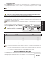
12. FUSIBILI DI PROTEZIONE
FUSIBILE
PROTEZIONE
FUSIBILE
PROTEZIONE
FUSIBILE
PROTEZIONE
FUSIBILE
PROTEZIONE
F1
=T10A
250V - 5x20
Alimentazio-
ne 24V~
F2
=T0.63A
250V - 5x20
Alimentazio-
ne accessori
e caricabat-
terie
F3
=R0.63A
250V - 5x20
Uscita lam-
peggiante
F4
=R3.15A
250V - 5x20
Uscita elettro-
serratura
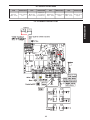
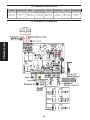
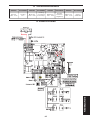
13. SCHEMA DI COLLEGAMENTO
Page is loading ...
Page is loading ...
Page is loading ...

12
ENGLISH
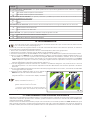
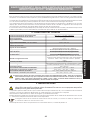
CE DECLARATION OF CONFORMITY
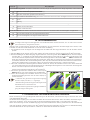
Notes on reading the instruction
Read this installation manual to the full before you begin installing the product.
The symbol indicates notes that are important for the safety of persons and for the good condition of the
automated system.
The symbol draws your attention to the notes on the characteristics and operation of the product.
Manufacturer: GENIUS S.p.A.
Address: Via Padre Elzi, 32 - 24050 - Grassobbio- Bergamo - ITALY
Declares that: Control unit mod. BRAIN 03 - BRAIN 04
• conforms to the essential safety requirements of the following EEC directives:
73/23/EEC and subsequent amendment 93/68/EEC.
89/336/EEC and subsequent amendment 92/31/EEC and 93/68/EEC
Additional information:
This product underwent a test in a typical uniform configuration (all products manufactured by GENIUS S.p.A.).
Grassobbio, 10-01-2007
Managing Director
D. Gianantoni
INDEX
1. GENERAL CHARACTERISTICS page.13
2. TECHNICAL SPECIFICATIONS page.13
3. PRELIMINARY SETTING-UP page.13
4. CONNECTIONS AND OPERATION page.14
4.1. TERMINAL BOARD CN1 page.14
4.2. TERMINAL BOARD CN2 page.14
4.3. TERMINAL BOARD CN3 page.15
4.4. TERMINAL BOARD CN4 page.15
5. INSTALLING THE RADIO CONTROL RECEIVER BOARD page.16
6. OPERATION WITH ENCODER OR AMPEROMETRIC OPERATION page.16
7. CONTROL LEDS page.16
8. OPERATION OF DISPLAY page.16
9. ADJUSTING THE OPERATING PARAMETERS page.17
10. PROGRAMMING page.18
11. OPERATION OF ELECTRONIC CLUTCH page.18
12. PROTECTION FUSES page.19
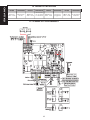
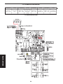
13. CONNECTION LAY-OUT page.19
14. FUNCTION LOGICS page.20
15. HOW TO SECURE THE BOARD page.22

13
ENGLISH
24 Vdc ELECTRONIC CONTROL UNIT FOR SWING GATES
USE INSTRUCTIONS - INSTALLATION INSTRUCTIONS
1. GENERAL CHARACTERISTICS
This 24 Vdc control unit for swing gates offers high performance and a wide range of adjustments: opening and closing
decelerations, possibility of managing one or two motors, management of opening and closing limit-switches, and the
possibility of managing two
TIMECODERS
.
A sophisticated electronic control constantly monitors the power circuit and disables the control unit in the event of
malfunctions that could impair efficiency of the electronic clutch.
The parameter settings and the operating logics are set and shown on a handy display, which indicates gate status
during normal operation. Operating times are adjusted by self-learning during programming.
The water-tight enclosure is designed to house the control unit, the toroidal transformer and any buffer batteries (op-
tional) having the characteristics and dimensions indicated in the table below.
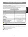
2. TECHNICAL SPECIFICATIONS
Supply voltage of transformer
Supply voltage of transformer
230/115 V~ (+6 -10%) - 50/60 Hz.
230/115 V~ (+6 -10%) - 50/60 Hz.
Supply voltage of control unit
Supply voltage of control unit
24 V~ (+6 -10%) - 50/60 Hz.
24 V~ (+6 -10%) - 50/60 Hz.
Absorbed power
3 W
Motor max load
70 W x 2
Accessories max load
24Vdc 500mA
Flashing lamp/Courtesy light max. load
Flashing lamp/Courtesy light max. load
24Vdc 15W max.
Operating ambient temperature
Operating ambient temperature
-20°C +50°C
Protection fuses
4
Function logics
Automatic / Stepped Automatic / Semiautomatic / Step-
ped Semiautomatic / Condo type
Opening / closing time
Opening / closing time
Through self-learning during programming
Through self-learning during programming
Pause time
Through self-learning during programming
Through self-learning during programming
Thrust force
Four levels adjustable on display
Decelerations
Opening and closing
Power supply 24V~ / Battery supply / Encoder
Terminal board inputs
Total opening / Pedestrian opening / Opening-closing
safety devices / Stop / Opening-closing limit-switch
safety devices / Stop / Opening-closing limit-switch
Radio connector
Rapid 5-pin connector
Terminal board outputs
24Vdc power supply to accessories / 24 Vdc Motors / 24
Vdc Courtesy light-Flashing lamp / 12 Vdc/~ Electric lock
Vdc Courtesy light-Flashing lamp / 12 Vdc/~ Electric lock
Board dimensions
165 x 130 mm.
Characteristics of 230V~ toroidal transformer
prim. 230V~ / sec. 22V~ / 120VA
Characteristics of 115V~ toroidal transformer
prim. 115V~ / sec. 20V~ / 120VA
Characteristics of optional batteries
12V - 4 Ah / dimens. 90 x 70 x 108 mm.
Characteristics of outdoor enclosure
306 x 225 x 130 mm. - IP55
Different output values can be obtained on the 24V~ voltage depending on the mains voltage value. Before
start-up, always check the transformer output voltage. This must not exceed 26V~ for both 230V~ and 115V~
power supply. Voltage must be measured load free, i.e. with the transformer powered and disconnected from
the board.
3. PRELIMINARY SETTING-UP
To ensure people’s safety, all warnings and instructions in this booklet must be carefully observed. Incorrect
installation or incorrect use of the product could cause serious harm to people.
Make sure there is an adequate differential switch upstream of the system as specified by current laws, and install an
all-pole thermal breaker on the power supply mains.
To lay electric cables, use adequate rigid and/or flexible pipes.
Always separate the connection cables of low voltage accessories from the 115/230 V~ power cables. To prevent any
interference whatever, use separate sheaths.
Maximum length of power cables between control unit and motors must not exceed 10 m, using cables of
2.5mm² diameter.
To secure the various components inside of the airtight enclosure, refer to paragraph 15.

14
ENGLISH
4. CONNECTIONS AND OPERATION
4.1. TERMINAL BOARD CN1
4.1.1. POWER SUPPLY 22V
“
VAC-VAC
” terminals. The secondary circuit of the 24V~ 50/60 Hz transformer should be connected to this input. Power
supplied by the transformer is signalled by the lighting of the “
ALIM
” LED located under the terminal board.
4.1.2. BATTERIES
“
+BAT - -BAT
” terminals. Connect the power cables of the buffer batteries (optional) to these terminals. The control unit
is designed to operate with two buffer batteries, with the minimum characteristics shown on the table in paragraph
2. During normal operation, the unit keeps the batteries charged and these start operating if no power is supplied to
the transformer.
Power supplied by batteries only should be considered an emergency situation. The number of possible
manoeuvres is linked to the quality of the batteries, the structure of the gate to be moved, the time elapsed
since power cut occurred, etc, etc.
Observe the battery power supply polarity.
4.1.3. ACCESSORIES
“
+24V - -24V
” terminals. The accessories power cables should be connected to these terminals.
The maximum load of the accessories must not exceed 500 mA.
The output of these terminals is DC - observe the power supply polarity of the accessories.
4.1.4. EARTH
“
“ terminal. The control unit earthing cable should be connected to this terminal.
This connection is absolutely necessary to ensure a correctly operating control unit.
4.2. TERMINAL BOARD CN2
4.2.1. GEARMOTOR 1
“
APM1 - CHM1
” terminals. For double leaf applications, connect to these terminals the gearmotor fitted on the leaf
which must move first. For single leaf applications, the gearmotor must be connected to these terminals. The maximum
load of the gearmotor must not exceed 70W.
4.2.2. GEARMOTOR 2
“
APM2 - CHM2
” terminals. For double leaf applications, connect to these terminals the gearmotor fitted on the leaf
which must move last. For single-leaf applications, nothing should be connected to these terminals. The maximum
load of the gearmotor must not exceed 70W.
4.2.3. ELECTRIC LOCK
“
ELS - ELS
”terminals. The electric lock, if any, with 12 Vdc/~ power supply, should be connected to these terminals. To
facilitate release of the electric lock, the over-pushing stroke can be input by enabling parameter “F” (see paragraph
9).
In double-leaf applications, install the electric lock on the leaf where gearmotor 1 is installed.
4.2.4. FLASHING LAMP / COURTESY LIGHT
“
LAMP - LAMP
” terminals. Both a flashing lamp and a courtesy light can be connected to these terminals, both with 24
Vdc power supply and maximum 15W. To make this output operational, select parameter “
G
”, see paragraph 9.
Flashing lamp operation:
During normal operation, the flashing lamp provides a fixed pre-flashing of 1.5 seconds during both opening and closing.
When the gate is open, and the closing safety devices are tripped, the lamp flashes to indicate that a manoeuvre is
taking place in the gate movement area. We advise you to connect the flashing lamp before programming, because
it indicates its phases. Use a fixed light flashing lamp; flashing is controlled by the control unit.
Courtesy light operation:
The courtesy light stays lighted for a fixed time of 90 seconds from the OPEN pulse, after which it goes OFF. Use a lamp
with 24 V power supply and maximum 15W.

15
ENGLISH
4.3. TERMINAL BOARD CN3
4.3.1. MOTOR 1 CLOSING LIMIT-SWITCH
“
COMF - FCC1
” terminals. Normally closed contact. This is tripped and stops the closing motion of motor 1. The status
of this input is signalled by LED
FCC1
.
4.3.2. MOTOR 1 OPENING LIMIT-SWITCH
“
COMF - FCA1
” terminals. Normally closed contact. This is tripped and stops the opening motion of motor 1. The status
of this input is signalled by LED
FCA1
.
4.3.3. MOTOR 2 CLOSING LIMIT-SWITCH
“
COMF - FCC2
” terminals. Normally closed contact. This is tripped and stops the closing motion of motor 2.The status
of this input is signalled by LED
FCC2
.
4.3.4. MOTOR 2 OPENING LIMIT-SWITCH
“
COMF - FCA2
” terminals. Normally closed contact. This is tripped and stops the opening motion of motor 2. The status
of this input is signalled by LED
FCA2
.
• If no limit-switch is used, jumper connect the inputs.
• The limit-switches cannot be used as the start of the decelerated section.
4.3.5. MOTOR 1 ENCODER
“
ENC1
” terminal. The signal received from the encoder installed on gearmotor 1 must be connected to this terminal.
For operation and activation of the encoder, see paragraph 6.
If no encoder is used, do not, on any account, jumper-connect the inputs
4.3.6. MOTOR 2 ENCODER
“
ENC2
” terminal. The signal received from the encoder installed on gearmotor 2 must be connected to this terminal.
For operation and activation of the encoder, see paragraph 6.
If no encoder is used, do not, on any account, jumper-connect the inputs
In two-motor applications, the encoder must be installed on both motors.
In two-motor applications, the encoder must be installed on both motors.
In two-motor applications, the encoder must be installed on both motors.
In two-motor applications, the encoder must be installed on both motors.
4.4. TERMINAL BOARD CN4
4.4.1. TOTAL OPENING
“
COM - OPEN A
”terminals. Normally open contact. Connect, to these terminals, any pulse generator (e.g. push-button,
key selector, etc.) which, by closing a contact, generates a gate total opening or closing pulse. The operation of this
generator is defined by parameter “
D
”, see paragraph 9.
• A total opening pulse always has priority over pedestrian opening.
• To connect several pulse generators, connect the devices in parallel.
4.4.2. PEDESTRIAN OPENING
“
COM - OPEN B
” terminals. Normally open contact. Connect, to these terminals, any pulse generator (e.g. push-but-
ton, key selector, etc..) which, by closing a contact, generates a gate partial opening or closing pulse. In double leaf
applications, pedestrian opening corresponds to total opening of leaf 1. In single leaf applications, pedestrian opening
corresponds to about 30% of memory-stored total opening.
• A total opening pulse always has priority over pedestrian opening.
• To connect several pulse generators, connect the devices in parallel.
• To connect several pulse generators, connect the devices in parallel.
• To connect several pulse generators, connect the devices in parallel.
4.4.3. STOP
“
COM - STOP
” terminals. Normally closed contact. Connect, to these terminals, any safety device (e.g. pressure switch,
safety edge, etc.) which, by opening a contact, immediately stops the gate and disables all automatic functions. The
status of this input is signalled by the “
STOP
” LED. The gate resumes its memory-stored cycle only by means of another
total or partial opening pulse.
• If no STOP devices are connected, jumper connect the input.
• To connect several STOP commands, connect the devices in series.
4.4.4. CLOSING SAFETY DEVICES
“
COM - FSW CL
”terminals. Normally closed contact. Connect, to these terminals, any safety device (e.g. photocell,
safety edge, pressure switch etc..) which, by opening a contact, affects the gate’s closing motion, reversing it to the
mechanical stop, or to the opening limit-switch. The status of this input is signalled by LED “
FSW-CL
”.

16
A2
ENGLISH
4.4.5. OPENING SAFETY DEVICES
“
COM - FSW OP
”terminals. Normally closed contact. Connect, to these terminals, any safety device (e.g. photocell,
safety edge, pressure switch etc..) which, by opening a contact, affects the gate’s opening motion, causing it to stop
immediately. When the safety device has been reset, the gate resumes its memory-stored cycle. The status of this
input is signalled by LED “
FSW-OP
”.
• If no safety devices are connected, jumper connect the inputs.
• To connect several safety devices, connect the devices in series.
5. INSTALLING THE RADIO CONTROL RECEIVER BOARD
The control unit is designed to house a 5-pin radio-receiver module. Installation procedure: turn off power and fit the
module in connector
CN5
on the control unit.
To avoid damaging the receiver and thus irreparably compromising its operation, the receiver must be installed
while observing the fitting direction specified in paragraph 13 (connection lay-out).
This done, observe the radio-receiver instructions to store the radio control in the memory.
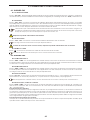
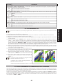
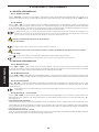
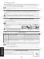
6. OPERATION WITH ENCODER OR AMPEROMETRIC OPERATION
The control unit has 4
DIP SWITCHES
, which enable selection of either amperometric operation or operation with
Encoder.
Operation with encoder provides greater safety in detecting obstacles and greater repeatability of the deceleration
point.
Operation with encoder requires mechanical stops, or limit-switches, for both opening and closing.
To select operation with encoder, position
DIP-SWITCHES 1
and
2
to
ON
and
DIP-SWITCHES 3
and
4
to
OFF
(Fig.01).
To select amperometric operation, position
DIP-SWITCHES 1
and
2
to
OFF
and
DIP-SWITCHES 3
and
4
to
ON
(Fig.02).
For a correct programming procedure of the control
unit, carry out this operation before programming
the control unit because it radically modifies its
operation.
7. CONTROL LEDS
LEDS
ON
OFF
ALIM
Power supply by toroidal transformer
Power supplied by batteries or no power supplied
FCC1
Motor 1 closing limit-switch not tripped
Motor 1 closing limit-switch tripped
FCA1
Motor 1 opening limit-switch not tripped
Motor 1 opening limit-switch tripped
FCC2
Motor 2 closing limit-switch not tripped
Motor 2 closing limit-switch tripped
FCA2
Motor 1 opening limit-switch not tripped
Motor 2 opening limit-switch tripped
STOP
Stop command not activated
Stop command activated
FSW-CL
Closing safety device not tripped
Closing safety device trippedù
FSW-OP
Opening safety device not tripped
Opening safety device tripped
• Indicated in bold: status of LEDs with gate closed, control unit powered, and both limit-switches installed.
• If the limit-switches are not used, the relevant contacts must be jumper connected and LEDs
FCC1
-
FCA1
-
FCC2
-
FCA2
must be lighted.
• If no
STOP
devices are connected, jumper connect the input. The
STOP
LED must be lighted.
8. OPERATION OF DISPLAY
The control unit has a handy display for viewing and programming the operating parameters. Furthermore, it constantly
shows gate status during normal operation.
When operating parameters are being displayed and programmed, the display shows the se-
lected parameter on the left, and its set value on the right. Fig. 03 shows the viewing example of
parameter “
A
” at value “
2
”.
Operation with
Encoder
Amperometric
operation
Fig. 01
Fig. 02
Fig. 03

17
ENGLISH
During normal operation, the display shows gate status. The displayed values are indicated on the following table:
DISPLAY VALUE
GATE STATUS
- -
Gate at rest
O P
Gate opening
t c
Gate open in pause status (Only with automatic re-closure enabled - see next paragraph)
C L
Gate closing
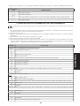
9. ADJUSTING THE OPERATING PARAMETERS
Before you begin adjusting the operating parameters, select the type of operation for the control unit: with
or without encoder (see paragraph 6).
To access operating parameter adjustment, follow the instructions below:
1- When you have made all the necessary connections, power up the system and check if all the signalling LEDs are
in the situation specified in paragraph 7.
2- The display shows value “
--
”.
3- Press and hold down push-button
P2
until the display shows the name and value of the first parameter.
4- Press push-button
P1
to change the value of the parameter.
5- To move on to the next parameter, press push-button
P2
.
6- When 60 seconds have elapsed without any key being touched, the control unit exits the adjustment mode. You can
manually exit the adjustment mode by scrolling all the parameters with push-button
P2
. When the display shows
value “
--
“, you have returned to normal operation.
The following table summarises all settable parameters and the assignable values.
DISPLAY
DESCRIPTION
Adjusting the sensitivity of the electronic clutch
A1
Minimum motor force
A2
Medium-low motor force
A3
Medium-high motor force
A4
High motor force
Leaf 2 delay:
this parameter enables you to select the offset time of the two leaves.
b1
1.5 seconds offset
b2
3 seconds offset
b3
6 seconds offset
b4
10 seconds offset
Automatic Reclosure:
this function enables or disables automatic gate reclosure.
c0
Disabled
c1
Enabled
Operation of OPEN A command:
this function determines the behaviour of the OPEN A (total opening)push-button.
d0
Opens / Closes / Opens.....
d1
Opens / Stops/ Closes / Stops / Opens......
Condo function:
if this function is enabled while the gate is being opened, the start command is inhibited.
E0
Disabled
E1
Enabled
Over pushing stroke:
if you enable this function, at every OPEN pulse, the leaf on which the electric lock is installed starts
its closing movement for a few seconds. This facilitates release of the electric lock.
its closing movement for a few seconds. This facilitates release of the electric lock.
its closing movement for a few seconds. This facilitates release of the electric lock.
F0
Disabled
F1
Enabled
Courtesy light/ Flashing lamp:
with this parameter, you can select the type of output from the LAMP - LAMP terminals,
selecting from among flashing lamp and courtesy light.
selecting from among flashing lamp and courtesy light.
selecting from among flashing lamp and courtesy light.
G0
Flashing lamp
G1
Courtesy light (active for 90 seconds)

18
ENGLISH
DISPLAY
DESCRIPTION
Deceleration point percentage:
this parameter is used to set the length of the decelerated section, selecting from the
two set values.
H0
40% of maximum memory-stored opening
H1
20% of maximum memory-stored opening
Speed during deceleration phase:
this parameter is used to set motor speed during the deceleration phase, selecting
it from the two values.
i0
High
i1
Low
Limit-switch operation:
this parameter enables you to select operation with or without the limit-switch.
L0
Operation without limit-switch
L1
Operation with limit-switch
Number of motors:
this parameter is used to select the type of gate: with one leaf or with two leaves
M1
Single-leaf gate, only one motor connected
M2
Double-leaf gate, two motors connected
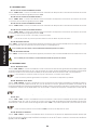
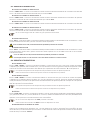
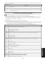
10. PROGRAMMING
Before you begin programming, select the type of operation for the control unit: with or without encoder (see
paragraph 6).
During the programming procedure, the control unit memory-stores the opening, closing mechanical stop points and
any pause time before re-closure.
1- Release the gearmotors, locate the leaves at half open point, and re-lock the operators.
2- Power up the control unit and check if value “
--
” is shown on the display.
3- Press and hold down push-button
P2
until the display shows the first parameter and relevant value.
4- Give an
OPEN A
command with any device connected to this input: the display shows value “
Pr
”, and the leaves
begin to move. The first manoeuvre performed by the leaves must be closing. If this does not happen, stop the
gate movement with a reset pulse. To do this, make a bridge between the two “
RESET
”
PINS
, using the connector
(see Fig.04). Cut power and put the connector back in its normal position (Fig. 04). Then change over the wires of
the motor/s, which had performed the opening operation. Resume the programming stage from point 1.
5- When the closing mechanical stop point is reached, the gearmotors pause for about 2 seconds, and then restart
with a total opening manoeuvre up to the opening mechanical stop point or up to the relevant limit-switch.
6- If automatic reclosure was not enabled, this means programming has finished, otherwise the control unit begins
counting pause time.
7- When the required time has elapsed, give another
OPEN A
pulse, and the gate will begin to close.
8- When the closing stop has been reached, programming
has terminated, and the display shows value “
--
”.
• The display shows value “” during the entire pro-
gramming procedure.
• The flashing lamp stays lighted on a fixed light
during the entire programming time.
• Leaf movement is decelerated during the pro-
gramming procedure.
11. OPERATION OF ELECTRONIC CLUTCH
This is a very important device for reasons of safety. Its setting stays unchanged long-term, without wear. It is active
during both closing and opening. When it operates, it reverses gate movement without disabling automatic closing
if activated.
If the clutch operates several consecutive times during the closing movement, the control unit goes into
STOP
status,
disabling any automatic command. If the clutch operates several consecutive times, this means that the obstacle
remains and it could be dangerous to perform any manoeuvre. To restore normal operation, the user must give an
OPEN A / OPEN B
pulse.
Fig. 04

19
ENGLISH
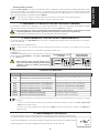
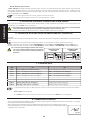
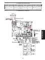
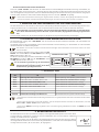
12. PROTECTION FUSES
FUSE
PROTECTION
FUSE
PROTECTION
FUSE
PROTECTION
FUSE
PROTECTION
F1
=T10A
250V - 5x20
Power supply
24V~
F2
=T0.63A
250V - 5x20
Supply to
accessories
and battery-
charger
F3
=R0.63A
250V - 5x20
Flashing lamp
output
F4
=R3.15A
250V - 5x20
Electric lock
output
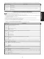
13. CONNECTION LAY-OUT

20
ENGLISH
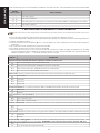
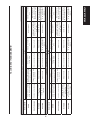
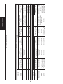
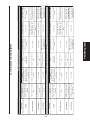
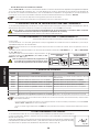
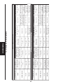
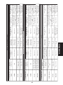
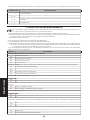
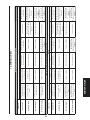
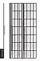
14. FUNCTION LOGICS
Automatic ”A” logic C=1 d=0 E=0
Gate status
Pulses
Open A
Open B
Stop
Opening safety devices
Opening safety devices
Closing safety devices
Closing safety devices
OP/CL safety device
Closed
Opens the leaf and re-
closes after pause time
Executes leaf partial
opening and re-closes
after pause time
No effect
(OPEN disabled)
Disables OPEN com-
mands
No effect
Disables OPEN com-
mands
Open on pause
Reloads pause time
Closes the gate
immediately
Stops operation
No effect
Stops closure. On relea-
se, closes after 5 sec., if
pause time has elapsed
Locks pause time, and
when released, closes
after 5 sec.
Closing
Reverses gate motion
No effect
Stops operation
No effect
Reverses motion
Stops operation and
reverses on release
Opening
Reverses gate motion
No effect
Stops operation
Stops operation and
resumes on release
No effect
Stops operation and
resumes on release
Stepped Automatic ”AP” logic C=1 d=1 E=0
Gate status
Pulses
Open A
Open B
Stop
Opening safety devices
Opening safety devices
Closing safety devices
Closing safety devices
OP/CL safety device
Closed
Opens the leaf and re-
closes after pause time
Executes leaf partial
opening and re-closes
after pause time
No effect
(OPEN disabled)
Disables OPEN com-
mands
No effect
Disables OPEN com-
mands
Open on pause
Reloads pause time
Closes the gate
immediately
Stops operation
No effect
Stops closure. On relea-
se, closes after 5 sec., if
pause time has elapsed
Locks pause time, and
when released, closes
after 5 sec.
Closing
Stops gate motion and
opens on next pulse
No effect
Stops operation
No effect
Reverses motion
Stops operation and
reverses on release
Opening
Stops gate motion and
closes on next pulse
No effect
Stops operation
Stops operation and
resumes on release
No effect
Stops operation and
resumes on release

21
ENGLISH
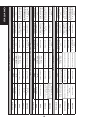
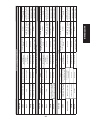
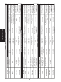
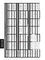
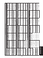
Semi-automatic ”E” logic C=0 d=0 E=0
Gate status
Pulses
Open A
Open B
Stop
Opening safety devices
Opening safety devices
Closing safety devices
Closing safety devices
OP/CL safety device
Closed
Opens the leaf
Executes partial opening
No effect
(OPEN disabled)
(OPEN disabled)
Disables OPEN com-
mands
No effect
Disables OPEN com-
mands
Open
Closes
Closes the gate
No effect
(OPEN disabled)
No effect
Disables OPEN com-
mand and, on release,
re-closes after 5 sec..
Disables OPEN com-
mand and, on release,
re-closes after 5 sec..
Closing
Reverses gate motion
No effect
Stops operation
No effect
Reverses gate motion
Stops operation and
reverses on release
Opening
Reverses gate motion
No effect
Stops operation
Stops operation and
resumes on release
No effect
Stops operation and
resumes on release
Stepped Semi-automatic ”EP” logic C=0 d=1 E=0
Gate status
Pulses
Open A
Open B
Stop
Opening safety devices
Opening safety devices
Closing safety devices
Closing safety devices
OP/CL safety device
Closed
Opens the leaf
Executes partial opening
No effect
(OPEN disabled)
(OPEN disabled)
Disables OPEN com-
mands
No effect
Disables OPEN com-
mands
Open
Closes
Closes the gate
No effect
(OPEN disabled)
No effect
Disables OPEN com-
mand and, on release,
re-closes after 5 sec..
Disables OPEN com-
mand and, on release,
re-closes after 5 sec..
Closing
Stops gate operation
and opens on next pulse
No effect
Stops operation
No effect
Reverses gate motion
Stops operation and
reverses on release
Opening
Stops gate operation
and opens on next pulse
No effect
Stops operation
Stops operation and
resumes on release
No effect
Stops operation and
resumes on release
Condo ”D” logic C=1 d=0 E=1
Gate status
Pulses
Open A
Open B
Stop
Opening safety devices
Opening safety devices
Closing safety devices
Closing safety devices
OP/CL safety device
Closed
Opens the leaf and re-
closes after pause time
Executes leaf partial
opening and re-closes
after pause time
No effect
(OPEN disabled)
Disables OPEN com-
mands
No effect
Disables OPEN com-
mands
Open on pause
Reloads pause time
Closes the gate
immediately
Stops operation
No effect
Disables OPEN com-
mand and, on release,
re-closes after 5 sec..
Disables OPEN com-
mand and, on release,
re-closes after 5 sec..
Closing
Reverses gate motion
No effect
Stops operation
No effect
Reverses gate motion
Stops operation and
reverses on release
Opening
No effect
No effect
Stops operation
Stops operation and
resumes on release
No effect
Stops operation and
resumes on release

22
ENGLISH
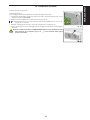
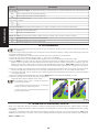
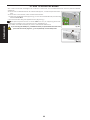
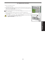
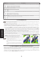
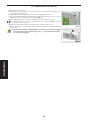
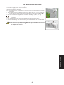
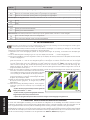
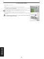
15. HOW TO SECURE THE BOARD
The outdoor enclosure is designed to house the control unit, the toroidal transformer and any buffer batteries
(Optional).
To secure the toroidal transformer and the board support, consult the specific instruc-
tions.
To secure the control board, follow the instructions below:
1. Position the supplied spacers (Fig.5 ref.) on the columns identified by the following
letters: A-C-I-P-Q-G.
2. Secure the board using the supplied screws (Fig.5 ref. ).
The spacers positioned next to letters A & P serve only for supporting the board.
3. Wire up according to the connection lay-out (paragraph 13).
4. To position and wire the battery kit, refer to the relevant instructions.
If you are using the battery kit, you MUST clear the pre-perforated hole in the lower
part of the enclosure (Fig.6 ref. ) as requested by current safety laws.
Fig. 05
Fig. 06
Fig. 06
Page is loading ...
Page is loading ...
Page is loading ...
Page is loading ...
Page is loading ...
Page is loading ...
Page is loading ...

30
FRANÇAIS
12. FUSIBLES DE PROTECTION
FUSIBLE
PROTECTION
FUSIBLE
PROTECTION
FUSIBLE
PROTECTION
FUSIBLE
PROTECTION
F1
=T10A
250V - 5x20
Alimentation
24V~
F2
=T0.63A
250V - 5x20
Alimentation
accessoires
et chargeur
de batteries
F3
=R0.63A
250V - 5x20
Sortie
clignotant
F4
=R3.15A
250V - 5x20
Sortie électro-
serrure
13. SCHÉMA DE CONNEXION
Page is loading ...
Page is loading ...
Page is loading ...
Page is loading ...
Page is loading ...
Page is loading ...
Page is loading ...
Page is loading ...
Page is loading ...
Page is loading ...
Page is loading ...
Page is loading ...
Page is loading ...
Page is loading ...
Page is loading ...
Page is loading ...
Page is loading ...
Page is loading ...
Page is loading ...
Page is loading ...
Page is loading ...
Page is loading ...
Page is loading ...
Page is loading ...
Page is loading ...
Page is loading ...
Page is loading ...
Page is loading ...
Page is loading ...
Page is loading ...
Page is loading ...
Page is loading ...
Page is loading ...
Page is loading ...
Page is loading ...
Page is loading ...
Page is loading ...
Page is loading ...
Page is loading ...

Le descrizioni e le illustrazioni del presente manuale non sono impegnative. La GENIUS si riserva il diritto, lasciando inalterate le carat-
teristiche essenziali dell’apparecchiatura, di apportare in qualunque momento e senza impegnarsi ad aggiornare la presente pub-
blicazione, le modifiche che essa ritiene convenienti per miglioramenti tecnici o per qualsiasi altra esigenza di carattere costruttivo
o commerciale.
The descriptions and illustrations contained in the present manual are not binding. GENIUS reserves the right, whilst leaving the main
features of the equipments unaltered, to undertake any modifications it holds necessary for either technical or commercial reasons,
at any time and without revising the present publication.
Les descriptions et les illustrations du présent manuel sont fournies à titre indicatif. GENIUS se réserve le droit d’apporter à tout moment
les modifications qu’elle jugera utiles sur ce produit tout en conservant les caractéristiques essentielles, sans devoir pour autant mettre
à jour cette publication.
Die Beschreibungen und Abbildungen in vorliegendem Handbuch sind unverbindlich. GENIUS behält sich das Recht vor, ohne die
wesentlichen Eigenschaften dieses Gerätes zu verändern und ohne Verbindlichkeiten in Bezug auf die Neufassung der vorliegenden
Anleitungen, technisch bzw. konstruktiv/kommerziell bedingte Verbesserungen vorzunehmen.
Las descripciones y las ilustraciones de este manual no comportan compromiso alguno. GENIUS se reserva el derecho, dejando
inmutadas las características esenciales de los aparatos, de aportar, en cualquier momento y sin comprometerse a poner al día la
presente publicación, todas las modificaciones que considere oportunas para el perfeccionamiento técnico o para cualquier otro
tipo de exigencia de carácter constructivo o comercial.
De beschrijvingen in deze handleiding zijn niet bindend. GENIUS behoudt zich het recht voor op elk willekeurig moment de verande-
ringen aan te brengen die het bedrijf nuttig acht met het oog op technische verbeteringen of alle mogelijke andere productie- of
commerciële eisen, waarbij de fundamentele eigenschappen van de apparaat gehandhaafd blijven, zonder zich daardoor te
verplichten deze publicatie bij te werken.
GENIUS S.p.A.
Via Padre Elzi, 32
24050 Grassobbio (BG) - ITALIA
Tel.: 035/4242511
Fax: 035/4242600
www.geniusg.Com
00058I0384 Rev.3
De beschrijvingen in deze handleiding zijn niet bindend. GENIUS behoudt zich het recht voor op elk willekeurig moment de verande-
ringen aan te brengen die het bedrijf nuttig acht met het oog op technische verbeteringen of alle mogelijke andere productie- of
commerciële eisen, waarbij de fundamentele eigenschappen van de apparaat gehandhaafd blijven, zonder zich daardoor te
verplichten deze publicatie bij te werken.
Timbro del Rivenditore:/ Distributor’s Stamp:/ Timbre de l’Agent:/ Fachhändlerstempel:/
Sello del Revendedor:/ Stempel van de dealer:
-
 1
1
-
 2
2
-
 3
3
-
 4
4
-
 5
5
-
 6
6
-
 7
7
-
 8
8
-
 9
9
-
 10
10
-
 11
11
-
 12
12
-
 13
13
-
 14
14
-
 15
15
-
 16
16
-
 17
17
-
 18
18
-
 19
19
-
 20
20
-
 21
21
-
 22
22
-
 23
23
-
 24
24
-
 25
25
-
 26
26
-
 27
27
-
 28
28
-
 29
29
-
 30
30
-
 31
31
-
 32
32
-
 33
33
-
 34
34
-
 35
35
-
 36
36
-
 37
37
-
 38
38
-
 39
39
-
 40
40
-
 41
41
-
 42
42
-
 43
43
-
 44
44
-
 45
45
-
 46
46
-
 47
47
-
 48
48
-
 49
49
-
 50
50
-
 51
51
-
 52
52
-
 53
53
-
 54
54
-
 55
55
-
 56
56
-
 57
57
-
 58
58
-
 59
59
-
 60
60
-
 61
61
-
 62
62
-
 63
63
-
 64
64
-
 65
65
-
 66
66
-
 67
67
-
 68
68
-
 69
69
-
 70
70
-
 71
71
-
 72
72


Genius Brain 03 and Brain 04 Owner's manual
- Category
- Gate Opener
- Type
- Owner's manual
- This manual is also suitable for
Ask a question and I''ll find the answer in the document
Finding information in a document is now easier with AI
in other languages
- italiano: Genius Brain 03 and Brain 04 Manuale del proprietario
- français: Genius Brain 03 and Brain 04 Le manuel du propriétaire
- español: Genius Brain 03 and Brain 04 El manual del propietario
- Deutsch: Genius Brain 03 and Brain 04 Bedienungsanleitung
- Nederlands: Genius Brain 03 and Brain 04 de handleiding
Related papers
-
Genius BRAIN03 BRAIN04 Operating instructions
-
-
Genius SPRINT 03 04 Operating instructions
-
-
-
-
Genius GEO 06 Operating instructions
-
-
-
Other documents
-
FAAC 424 D 24V Owner's manual
-
Key Gates CT102 User manual
-
Key Gates CT10224 User manual
-
-
-
 Key Automation CT202 24 Instructions And Warnings For Installation And Use
-
 Leb Electronics CTR17 User manual
-
Ducati CTR17 Owner's manual
-
-

