
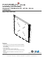
Features:
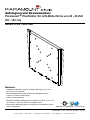
• Screen held only .73" (1.85 cm) from wall for ultra-slim installation
• Screen adapter plate simply slides into the wall plate for quick and
easy installation
• Colors: Gloss Black
• Screen adapter plates included compatible with
VESA 75 mm, 100 mm, 200 mm x 100 mm, and 200 mm mounting
patterns
• Includes hardware for installation to wood studs, concrete, and
cinder block
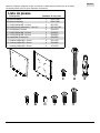
Installation and Assembly:
Paramount™ Flat Mount for 22" - 40" (56 - 102 cm)
LCD Screens
Model: PF632, PWV210/BK
Max UL Load Capacity: 115 lb (52.2 kg)
©
U
L
USC
I
D
:
0
0
0
0
0
1
8
7
6
2
ISSUED: 11-19-07 SHEET #: 202-9248-6 11-04-09
3215 W. North Ave. • Melrose Park, IL • (800) 865-2112 or (708) 865-8870 • Fax: (708) 865-2941 • www.peerlessmounts.com

2 of 36
ISSUED: 11-19-07 SHEET #: 202-9248-6 11-04-09
Note: Read entire instruction sheet before you start installation and assembly.
Table of Contents
Parts List.................................................................................................................................................................................3
Installation to Single Wood Stud Wall .....................................................................................................................................4
Installation to Solid Concrete or Cinder Block ........................................................................................................................5
Attaching Mounting Plate to Screen with VESA Mounting Patterns .......................................................................................6
Installing and Removing Flat Panel Screen............................................................................................................................8
• Do not begin to install your Peerless product until you have read and understood the instructions and warnings
contained in this Installation Sheet. If you have any questions regarding any of the instructions or warnings, for US
customers please call Peerless customer care at 1-800-865-2112, for all international customers, please contact
your local distributor.
• This product should only be installed by someone of good mechanical aptitude, has experience with basic building
construction, and fully understands these instructions.
• Make sure that the supporting surface will safely support the combined load of the equipment and all attached
hardware and components.
• Never exceed the Maximum UL Load Capacity. See page one.
• If mounting to wood wall studs, make sure that mounting screws are anchored into the center of the studs. Use of
an "edge to edge" stud finder is highly recommended.
• Always use an assistant or mechanical lifting equipment to safely lift and position equipment.
• Tighten screws firmly, but do not overtighten. Overtightening can damage the items, greatly reducing their holding
power.
• This product is intended for indoor use only. Use of this product outdoors could lead to product failure and personal
injury.
• This product was designed to be installed on the following wall construction only;
WALL CONSTRUCTION HARDWARE REQUIRED
• Wood Stud Included
• Wood Beam Included
• Solid Concrete Included
• Cinder Block Included
• Metal Stud Do not attach except with Peerless Metal Stud Accessory Kit - ACC215;
(not evaluated by UL)
• Brick Contact Qualified Professional (not evaluated by UL)
• Other or unsure? Contact Qualified Professional
WARNING
Tools Needed for Assembly
• stud finder ("edge to edge" stud finder is recommended)
• phillips screwdriver
• drill
• 5/16" (8 mm) bit for concrete and cinder block wall
• 5/32" (4 mm) bit for wood stud wall
• level

3 of 36
ISSUED: 11-19-07 SHEET #: 202-9248-6 11-04-09
A
CD
B
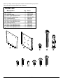
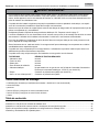
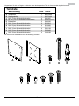
Before you begin, make sure all parts shown are included with your product.
Parts may appear slightly different than illustrated.
E
F
GH
J KL
Description
Qty. Part #
A
wall plate 1 095-P1498
B
mounting plate 1 095-P1499
C
M5 x 12 mm phillips screw 4 520-1027
D
#14 x 2.5" wood screw 2 5S1-015-C03
E
concrete anchor 2 590-0320
F
M4 x 10 mm phillips screw 4 504-9012
G
M4 x 20 mm phillips screw 4 504-9020
H
retaining spacer 4 590-5005
J
M6 x 12 mm phillips screw 4 520-1128
K
M6 x 20 mm phillips screw 4 520-9402
L
M6 x 30 mm phillips screw 4 510-9109
Parts List

4 of 36
ISSUED: 11-19-07 SHEET #: 202-9248-6 11-04-09
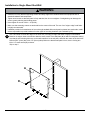
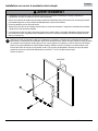
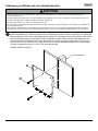
Installation to Single Wood Stud Wall
Use a stud finder to locate the edges of the stud. Use of an edge-to-edge stud finder is highly recommended.
Based on its edges, draw a vertical line down the stud’s center. Place wall plate (A) on wall as a template, making
sure that the two mounting holes are on the stud centerline. Level wall plate, and mark the center of the two holes.
Drill two 5/32" (4 mm) dia. holes 2.5" (64 mm) deep. Make sure that the wall plate is level, secure it using two
#14 x 2.5" wood screws (D) as shown.
Skip to step 2.
D
A
• Installer must verify that the supporting surface will safely support the combined load of the equipment and all
attached hardware and components.
• Tighten wood screws so that wall plate is firmly attached, but do not overtighten. Overtightening can damage the
screws, greatly reducing their holding power.
• Never tighten in excess of 80 in. • lb (9 N.M.).
• Make sure that mounting screws are anchored into the center of the stud. The use of an "edge to edge" stud finder
is highly recommended.
• Hardware provided is for attachment of mount through standard thickness drywall or plaster into wood studs. Install-
ers are responsible to provide hardware for other types of mounting situations (not evaluated by UL).
WARNING
1

5 of 36
ISSUED: 11-19-07 SHEET #: 202-9248-6 11-04-09
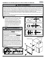
Installation to Solid Concrete or Cinder Block
Make sure that wall plate (A) is level, use it as a
template to mark two mounting holes. Drill two 5/16"
(8 mm) dia. holes to a minimum depth of 2.5"
(64 mm). Insert anchors (E) in holes flush with wall
as shown. Place wall plate over anchors and secure
with two #14 x 2.5" screws (D). Level, then tighten
all fasteners.
• When installing Peerless wall mounts on cinder block, verify that you have a minimum of 1-3/8" (35 mm) of actual
concrete thickness in the hole to be used for the concrete anchors. Do not drill into mortar joints! Be sure to mount
in a solid part of the block, generally 1" (25 mm) minimum from the side of the block. Cinder block must meet
ASTM C-90 specifications. It is suggested that a standard electric drill on slow setting is used to drill the hole
instead of a hammer drill to avoid breaking out the back of the hole when entering a void or cavity.
• Concrete must be 2000 psi density minimum. Lighter density concrete may not hold concrete anchor.
• Make sure that the supporting surface will safely support the combined load of the equipment and all attached hard-
ware and components.
WARNING
• Tighten screws so that wall plate is firmly attached,
but do not overtighten. Overtightening can damage
screws, greatly reducing their holding power.
• Never tighten in excess of 80 in. • lb (9 N.M.).
• Always attach concrete expansion anchors directly
to load-bearing concrete.
• Never attach concrete expansion anchors to
concrete covered with plaster, drywall, or other
finishing material. If mounting to concrete surfaces
covered with a finishing surface is unavoidable (not
evaluated by UL), the finishing surface must be
counterbored as shown below. Be sure concrete
anchors do not pull away from concrete when
tightening screws. If plaster/drywall is thicker than
5/8" (16 mm), custom fasteners must be supplied by
installer (not evaluated by UL).
WARNING
D
CINDER
BLOCK
SOLID
CONCRETE
A
E
1
1
3
2
E
Drill holes and insert anchors (E).
Place plate (A) over anchors (E) and secure with screws (D).
Tighten all fasteners.
A
E
D
concrete
surface
CUTAWAY VIEW
INCORRECT CORRECT
wall
plate
wall
plate
plaster/
dry wall
plaster/
dry wall
concrete
concrete

6 of 36
ISSUED: 11-19-07 SHEET #: 202-9248-6 11-04-09
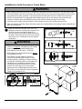
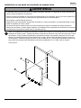
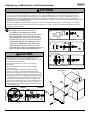
Attaching Mounting Plate to Screen
For VESA
®
50, 75 or 100 Mounting Pattern:
Choose hole pattern as shown in detail 1 for VESA 50,
75 or 100 mounting pattern. Attach mounting plate (B)
to back of screen using four M4 x 10 mm screws (F) as
shown.
NOTE: Be certain bottom flanges of mounting plate (B)
face toward bottom of screen.
*NOTE: If hole pattern is in a pocket, attach mounting
plate (B) to back of screen using four M4 x 20 mm
screws (G) and four retaining spacers (H) as indicated.
Skip to step 3.
2
• If screws don't get three complete turns in the screen inserts or if screws bottom out and bracket is still not tightly
secured, damage may occur to screen or product may fail.
WARNING
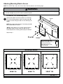
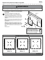
Mounting Patterns
VESA
®
75 VESA
®
100VESA
®
50
DETAIL 1
H
*For screens with a hole
pattern in a pocket, spacers (H)
go between mounting
plate (B) and screen when
using screw (G).
NOTE: For VESA
®
200 x 100, 120 x 180 or 200 x 200 hole patterns, see following page.
B
F or G
BOTTOM
FLANGES
SCREEN

7 of 36
ISSUED: 11-19-07 SHEET #: 202-9248-6 11-04-09
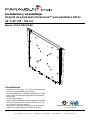
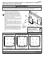
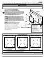
Attaching Mounting Plate to Screen with VESA
®
200 x 100, 120 x 180 or
200 x 200 Mounting Pattern
• If screws don't get three complete turns in the screen inserts or if screws bottom out and bracket is still not tightly
secured, damage may occur to screen or product may fail.
WARNING
FOR VESA
®
200 x 100, 120 x 180 or 200 x 200
MOUNTING PATTERN:
Choose hole pattern as shown in detail 2 for VESA
200 x 100, 120 x 180 or 200 x 200 mounting pattern
and for fasteners to use. Attach mounting plate (B) to
back of screen using four screws (F, G, J, K, or L) as
shown.
NOTE: Be certain bottom flanges of mounting plate
face toward bottom of screen.
*NOTE: If hole pattern is in a pocket, attach mounting
plate (B) to back of screen using four M4 x 20 mm
screws (G) and four retaining spacers (H) as indicated.
NOTE: If screw (J) gets less than three threads of
engagement, attach mounting plate (B) to back of
screen using four M6 x 20 mm screws (K). If screw (K)
still gets less than three threads of engagement, use
four M6 x 30 mm screws (L).
2
B
F, G, J, K or L
BOTTOM
FLANGES
Mounting Patterns
VESA
®
120 x 180 VESA
®
200 x 200VESA
®
200 x 100
DETAIL 2
SCREEN
M4 x 10 mm screws (F) or
M4 x 20 screws (G) with spacer (H)
M4 x 10 mm screws (F) or
M4 x 20 screws (G) with spacer (H)
M6 x 12 mm screws (J),
M6 x 20 mm screws (K) or
M6 x 30 mm screws (L)
NOTE: Fastener selection may vary for specific screens. If you have any questions for the correct fasteners to use for your
particular screen, call customer care.
H
*For screens with a
hole pattern in a pocket,
spacers (H) go between
mounting plate (B) and
screen when using
screws (G).

8 of 36
ISSUED: 11-19-07 SHEET #: 202-9248-6 11-04-09
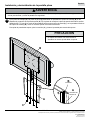
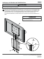
Attach mounting plate (B) to wall plate (A) by sliding flanges of mounting plate (B) into hook flanges of wall
plate (A). Secure mounting plate to wall plate using four M5 x 12 mm phillips screws (C) through bottom
flanges of wall plate (A) and into bottom flanges of mounting plate (B) as shown. Tighten screws securely.
To remove screen from mount, remove screws (C) and lift screen off of mount.
Installing and Removing Flat Panel Screen
3
• Do not lift more weight than you can handle. Use additional man power or mechanical lifting equipment to safely
handle placement of the screen.
WARNING
• Do not tighten screws with excessive force.
Overtightening can cause damage to mount.
CAUTION
B
A
HOOK
FLANGES
FLANGES
A
B
C
© 2009, Peerless Industries, Inc. All rights reserved.
All other brand and product names are trademarks or registered trademarks of their respective owners.
Peerless Industries, Inc.
3215 W. North Ave.
Melrose Park, IL 60160
www.peerlessmounts.com
Page is loading ...
Page is loading ...
Page is loading ...
Page is loading ...
Page is loading ...
Page is loading ...
Page is loading ...
Page is loading ...
Page is loading ...
Page is loading ...
Page is loading ...
Page is loading ...
Page is loading ...
Page is loading ...
Page is loading ...
Page is loading ...
Page is loading ...
Page is loading ...
Page is loading ...
Page is loading ...
Page is loading ...
Page is loading ...
Page is loading ...
Page is loading ...

ISSUED: 11-19-07 SHEET #: 202-9248-5 04-16-09
© 2008 Peerless Industries, Inc.
Peerless Industries, Inc. establishes a warranty period of five years for products manufactured or supplied by Peerless. This period commences from the date of
sale of the product to the original consumer, but will in no case last for more than six years after the date of the product’s manufacture. During the warranty period
such products will be free from defects in material and workmanship, provided they are installed and used in compliance with the instructions established by
Peerless Industries, Inc. Subject to applicable legal requirements, during the warranty period Peerless will repair or replace, or refund the purchase price of, any
such product which fails to conform with this warranty.
Any other warranties prescribed by the law which may apply with respect to such products also are limited in duration to the warranty period specified in this
Limited Five-Year Warranty.
This warranty does not cover damage caused by (a) service or repairs by the customer or a person who is not authorized for such service or repairs by Peerless
Industries, Inc., (b) the failure to utilize proper packing when returning the product, (c) incorrect installation or the failure to follow Peerless’ instructions or warnings
when installing, using or storing the product, or (d) misuse or accident, in transit or otherwise, including in cases of third party actions and force majeure.
In no event shall Peerless be liable for incidental or consequential damages or damages arising from the theft of any product, whether or not secured by a security
device which may be included with the product.
This Limited Five-Year Warranty is in lieu of all other warranties, expressed or implied, and is the sole remedy with respect to product defects. No retailer, dealer,
distributor, installer or other person is authorized to modify or extend this warranty or impose any obligation on Peerless in connection with the sale of any product
manufactured or supplied by Peerless.
This warranty gives specific legal rights, and you may also have other rights provided by the national legislation of the country in which you purchased such
product.
LIMITED FIVE-YEAR WARRANTY
www.peerlessmounts.com
Page is loading ...
Page is loading ...
Page is loading ...
-
 1
1
-
 2
2
-
 3
3
-
 4
4
-
 5
5
-
 6
6
-
 7
7
-
 8
8
-
 9
9
-
 10
10
-
 11
11
-
 12
12
-
 13
13
-
 14
14
-
 15
15
-
 16
16
-
 17
17
-
 18
18
-
 19
19
-
 20
20
-
 21
21
-
 22
22
-
 23
23
-
 24
24
-
 25
25
-
 26
26
-
 27
27
-
 28
28
-
 29
29
-
 30
30
-
 31
31
-
 32
32
-
 33
33
-
 34
34
-
 35
35
-
 36
36


Peerless Industries PARAMOUNT PF632 User manual
- Category
- Flat panel wall mounts
- Type
- User manual
Ask a question and I''ll find the answer in the document
Finding information in a document is now easier with AI
in other languages
Related papers
-
Peerless SUF640P User manual
-
Peerless Industries SUF650P User manual
-
-
-
-
-
Peerless Industries SUA746PU User manual
-
-
-
Other documents
-
MSI G52-66502X2 Datasheet
-
-
-
-
-
-
-
-
-