ENGLISH
Operating conditions
◗ This product is an Uninterruptible
Power Supply (UPS) for computers
and their peripherals, television
sets, stereo systems and video
recorders... It must not be used to
supply other electrical equipment
(lighting, heating, household
appliances, etc.).
◗ UPS can be installed in horizontal,
vertical position, or placed in Rack
2U (optional kit).
UPS connections
◗ Connect the UPS 1 to the
AC-power system via a wall outlet
with an earth connector, using the
supplied cord 2 for a UPS with
FR/DIN sockets or with the supply
cord of your computer for a UPS
with IEC/UNIVERSAL sockets (see
gure A).
◗ Plug critical equipment
(computer, monitor, modem, etc.)
into the outlets 9 providing
battery backup power and surge
protection (see gure B), taking
care not to exceed the rated current
indicated in amperes.
◗ Other devices (printer, scanner,
fax, etc.) can be connect to the
ltered outlets 8 that provide
surge protection (see gure B). The
ltered outlets are not backed up
by battery power in the event of a
power outage.
◗ Optional Internet modem /
Network connection:
A modem or Ethernet data line
can be protected against surges by
connecting it via the UPS. Connect
the existing device cable between
the wall outlet and the UPS, and
use a similar cable between the
UPS and the device, as indicated in
gure C (cable 3 not supplied).
◗ Optional COM connection:
The UPS devices with
communication (COM) sockets
can be connected to the computer
using the special USB or serial
cable 6 supplied.
The software available on the
CD-ROM 7 (or downloadable
from the eaton.com site) can be
congured to monitor the UPS
and the supply of power to the
computer (see gures D and F).
◗ Follow the indicated procedure.
◗ At the same time, register for the
warranty on the www.eaton.com
site (see gure G).
◗ Battery charge: The UPS charges
the battery as soon as it is
connected to the AC outlet, whether
button 13 is pressed or not. When
used for the rst time, the battery
will only provide its maximum
autonomy after it has been charged
for 8 hours. It is recommended that
the UPS be permanently connected
to the AC power supply to ensure
the best possible autonomy.
◗ Switching-on the UPS: press
button 13 for about 1 second.
◗ Filtered outlets 8 without
battery backup: Equipment
connected to these outlets is
supplied as soon as the AC cord 2
is plugged in. They are not affected
by button 13 .
◗ Battery backup outlets 9 :
Equipment connected to these
outlets is supplied as soon as
button 13 turns green (see gure
E). These outlets can be turned on
even if the UPS is not connected to
AC power (button 13 ashes).
◗ AC-power disturbance: If AC
power is disturbed or fails, the UPS
continues to operate on battery
power. Button 13 ashes green.
In normal mode, the audio alarm
beeps every ten seconds, then
every three seconds when the end
of battery backup time is near. In
silent mode (see the section on
settings), the audio alarm simply
beeps once when the UPS transfers
to battery power.
◗ If the power outage lasts longer
than the battery backup time, the
UPS shuts down and automatically
restarts when power is restored.
Following a complete discharge, a
few hours are required to recharge
the battery back to full backup time.
◗ To save battery power, it is
possible to press button 13 to cut
the supply of power to the devices
connected to the battery backup
outlets.
◗ Lightning protection: All outlets,
whether backed up or simply
ltered, include surge protection,
whatever the position of button
13 .
◗ Shutdown of the battery backup
outlets 9 : Press button 13 for
more than two seconds.
Battery disposal and safety
◗ Caution. Battery service life is
reduced by 50% for every ten
degrees above 25°C.
◗ The battery elements must be
replaced exclusively by qualified
personnel (risk of electrocution),
with new elements approved by
EATON to ensure correct operation
of the UPS.
◗ The battery must be disposed
of in accordance with applicable
regulations. To remove the
battery elements, shut down the
UPS (button 13 OFF), remove
the power cord and proceed
as indicated in page 4 "Battery
change".
◗ Warning: take care not to inverse
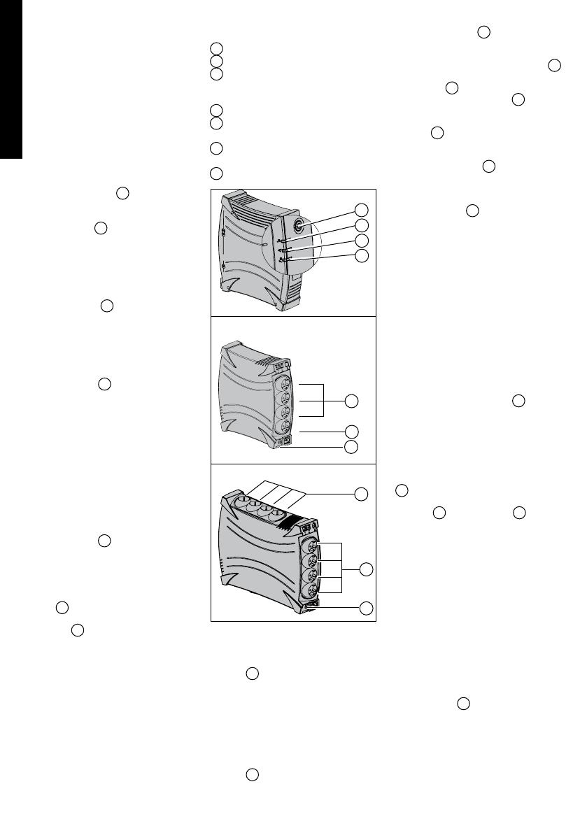
Ellipse MAX 600
Ellipse MAX 850/1100 /1500
8
13
12
11
10
Operation
8 : Filtered outlets.
9 : Battery backup outlets.
10 : LED ON indicate that surge
protection is active on all
outlets
.
11 : LED ON indicate a UPS fault.
12 : LED ON indicate an overload
on the battery backup outlets.
13 : ON/OFF button for the battery
backup outlets.
14 : Protection circuit breaker.
8
9
14
9
14


